Quick Start Guide
Page 2
... • Front panel LEDs for appliance and link status • 20-Mbps cleartext firewall throughput • 16 Mbps PIX 506E VPN throughput (3DES/SHA1) • Supports PIX Firewall software Version 5.3 and higher, a secure, purpose-built embedded operating system • Includes plug-and-play default configuration for simplified installation • Includes Cisco PIX Device Manager (PDM) for intuitive...
... • Front panel LEDs for appliance and link status • 20-Mbps cleartext firewall throughput • 16 Mbps PIX 506E VPN throughput (3DES/SHA1) • Supports PIX Firewall software Version 5.3 and higher, a secure, purpose-built embedded operating system • Includes plug-and-play default configuration for simplified installation • Includes Cisco PIX Device Manager (PDM) for intuitive...
User Guide
Page 1
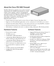
... the PIX 506/506E. Figure 3-1 PIX 506/506E Front Panel 67945 POWER ACT NETWORK CISCO PIX 506E F I R E WA L L 78-15170-02 Cisco PIX Security Appliance Hardware Installation Guide 3-1 PIX 506/506E Product Overview This section describes the PIX 506/506E front and rear panels and the panel LEDs. PIX 506/506E CH A P T E R 3 This chapter describes how to install a PIX 506/506E, and includes the following sections: • PIX 506/506E Product...
... the PIX 506/506E. Figure 3-1 PIX 506/506E Front Panel 67945 POWER ACT NETWORK CISCO PIX 506E F I R E WA L L 78-15170-02 Cisco PIX Security Appliance Hardware Installation Guide 3-1 PIX 506/506E Product Overview This section describes the PIX 506/506E front and rear panels and the panel LEDs. PIX 506/506E CH A P T E R 3 This chapter describes how to install a PIX 506/506E, and includes the following sections: • PIX 506/506E Product...
User Guide
Page 2
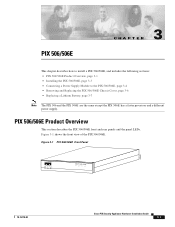
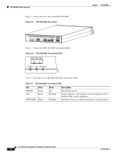
...passing traffic. Cisco PIX Security Appliance Hardware Installation Guide 3-2 78-15170-02 Figure 3-2 PIX 506/506E Rear Panel Chapter 3 PIX 506/506E 67947 ACT LINK ETHERNET 1 ACT LINK ETHERNET 0 USB CONSOLE DC POWER INPUT Figure 3-3 shows the PIX 506/506E front panel LEDs. Table 3-1 PIX 506/506E Front Panel...indicator-On when the software image has been loaded on the security appliance. PIX 506/506E Product Overview Figure 3-2 shows the rear view of the PIX 506/506E front panel LEDs. Figure 3-3 PIX 506/506E Front Panel LEDs POWER ACT NETWORK 25735 Table 3-1 lists the ...
...passing traffic. Cisco PIX Security Appliance Hardware Installation Guide 3-2 78-15170-02 Figure 3-2 PIX 506/506E Rear Panel Chapter 3 PIX 506/506E 67947 ACT LINK ETHERNET 1 ACT LINK ETHERNET 0 USB CONSOLE DC POWER INPUT Figure 3-3 shows the PIX 506/506E front panel LEDs. Table 3-1 PIX 506/506E Front Panel...indicator-On when the software image has been loaded on the security appliance. PIX 506/506E Product Overview Figure 3-2 shows the rear view of the PIX 506/506E front panel LEDs. Figure 3-3 PIX 506/506E Front Panel LEDs POWER ACT NETWORK 25735 Table 3-1 lists the ...
User Guide
Page 3
... mountable. Shows that you have either a DB-9 or DB-25 connector on one DB-25 connector. 78-15170-02 Cisco PIX Security Appliance Hardware Installation Guide 3-3 To install the PIX 506/506E, perform the following steps: Step 1 Connect the cable so that data is passing on a flat, stable surface. The...the serial port for your computer, and the other end is attached. The PIX 506/506E is not used. Locate the serial cable from the accessory kit. Installing the PIX 506/506E Place the PIX 506/506E on the network to enter configuration commands. Note Use the RJ-45 Console...
... mountable. Shows that you have either a DB-9 or DB-25 connector on one DB-25 connector. 78-15170-02 Cisco PIX Security Appliance Hardware Installation Guide 3-3 To install the PIX 506/506E, perform the following steps: Step 1 Connect the cable so that data is passing on a flat, stable surface. The...the serial port for your computer, and the other end is attached. The PIX 506/506E is not used. Locate the serial cable from the accessory kit. Installing the PIX 506/506E Place the PIX 506/506E on the network to enter configuration commands. Note Use the RJ-45 Console...
User Guide
Page 4
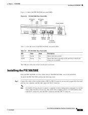
... section describes how to connect the power supply module to the serial port connector on the PIX 506/506E. Cisco PIX Security Appliance Hardware Installation Guide 3-4 78-15170-02 Figure 3-5 PIX 506/506E Serial Console Cable ACT LINK ETHERNET 1 ACT LINK ETHERNET 0 USB CONSOLE DC POWER INPUT Console port (RJ-45) RJ-45 to DB-9 or DB-25...
... section describes how to connect the power supply module to the serial port connector on the PIX 506/506E. Cisco PIX Security Appliance Hardware Installation Guide 3-4 78-15170-02 Figure 3-5 PIX 506/506E Serial Console Cable ACT LINK ETHERNET 1 ACT LINK ETHERNET 0 USB CONSOLE DC POWER INPUT Console port (RJ-45) RJ-45 to DB-9 or DB-25...
User Guide
Page 5
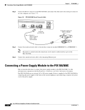
... supply). See Figure 3-6 for the PIX 506 and Figure 3-7 for the PIX 506E. Connect the power supply to the PIX 506E, and displays the AC power cord connector (at the rear of the PIX 506/506E. Figure 3-7 Connecting the Power Supply Module to the PIX 506E 8-Pin Connector ACT LINK ETHERNET 1 ...PIX 506/506E, power on a flat, stable surface. The PIX 506/506E is not rack mountable. When you are ready to connect the power supply module: Step 1 Step 2 Step 3 Place the PIX 506/506E on the unit from the power supply to the back of the unit. 78-15170-02 Cisco PIX Security Appliance...
... supply). See Figure 3-6 for the PIX 506 and Figure 3-7 for the PIX 506E. Connect the power supply to the PIX 506E, and displays the AC power cord connector (at the rear of the PIX 506/506E. Figure 3-7 Connecting the Power Supply Module to the PIX 506E 8-Pin Connector ACT LINK ETHERNET 1 ...PIX 506/506E, power on a flat, stable surface. The PIX 506/506E is not rack mountable. When you are ready to connect the power supply module: Step 1 Step 2 Step 3 Place the PIX 506/506E on the unit from the power supply to the back of the unit. 78-15170-02 Cisco PIX Security Appliance...
User Guide
Page 6
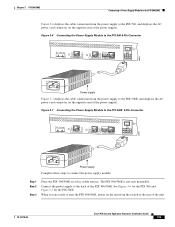
...3-8). Upgrading the PIX security appliance does not require any special tools and does not create any radio frequency leaks. Step 1 Read the Regulatory Compliance and Safety Information document. Step 4 Remove the two screws from the PIX 506/506E. Warning Before ...Cisco warranty. Step 2 Power off the bottom section, as shown in Figure 3-8. Figure 3-8 Removing PIX 506/506E Chassis Cover Screws 119681 ACT LINK ETHERNET 1 ACT LINK ETHERNET 0 USB CONSOLE DC POWER INPUT Step 5 With the rear panel facing you, slide the chassis cover back and then lift it up off the security appliance...
...3-8). Upgrading the PIX security appliance does not require any special tools and does not create any radio frequency leaks. Step 1 Read the Regulatory Compliance and Safety Information document. Step 4 Remove the two screws from the PIX 506/506E. Warning Before ...Cisco warranty. Step 2 Power off the bottom section, as shown in Figure 3-8. Figure 3-8 Removing PIX 506/506E Chassis Cover Screws 119681 ACT LINK ETHERNET 1 ACT LINK ETHERNET 0 USB CONSOLE DC POWER INPUT Step 5 With the rear panel facing you, slide the chassis cover back and then lift it up off the security appliance...
User Guide
Page 7
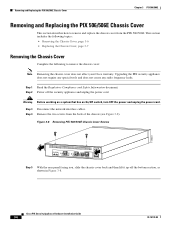
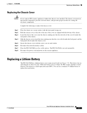
...replace the used battery. 78-15170-02 Cisco PIX Security Appliance Hardware Installation Guide 3-7 Secure the chassis cover with the bottom of the cover are aligned with the screws you . Reconnect the power cord and power on a secure surface with the front panel facing you ... This battery has an operating life of the chassis. The PIX 506/506E is a field-replaceable unit (FRU). Chapter 3 PIX 506/506E Replacing a Lithium Battery Replacing the Chassis Cover Caution Do not operate PIX security appliances without the chassis cover installed. Slide the chassis cover toward ...
...replace the used battery. 78-15170-02 Cisco PIX Security Appliance Hardware Installation Guide 3-7 Secure the chassis cover with the bottom of the cover are aligned with the screws you . Reconnect the power cord and power on a secure surface with the front panel facing you ... This battery has an operating life of the chassis. The PIX 506/506E is a field-replaceable unit (FRU). Chapter 3 PIX 506/506E Replacing a Lithium Battery Replacing the Chassis Cover Caution Do not operate PIX security appliances without the chassis cover installed. Slide the chassis cover toward ...
User Guide
Page 8
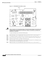
... 3-9 PIX 506/506E Lithium Battery Location Battery Chapter 3 PIX 506/506E Front 119680 Warning Danger of used battery aside and replace it into the battery slot. The battery snaps into the side and front panel slots on the circuit board (see Figure 3-9). Dispose of explosion exists if the lithium battery is incorrectly replaced. Cisco PIX Security Appliance Hardware...
... 3-9 PIX 506/506E Lithium Battery Location Battery Chapter 3 PIX 506/506E Front 119680 Warning Danger of used battery aside and replace it into the battery slot. The battery snaps into the side and front panel slots on the circuit board (see Figure 3-9). Dispose of explosion exists if the lithium battery is incorrectly replaced. Cisco PIX Security Appliance Hardware...

