Quick Start Guide
Page 2
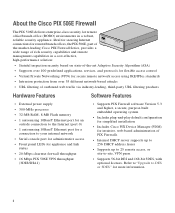
... default configuration for simplified installation • Includes Cisco PIX Device Manager (PDM) for intuitive, web-based administration of PIX Firewalls • Internal DHCP server supports up to 256 DHCP address leases • Supports up to 25 remote access, or site-to DES or 3DES" for remote/branch offices, the PIX 506E, part of CISCO FIRE PIX 506E WALL the market-leading Cisco PIX Firewall Series, provides a wide range of rich security capabilities and remote management capabilities in a robust, reliable security appliance. Refer to"Upgrade to -site, VPN...
... default configuration for simplified installation • Includes Cisco PIX Device Manager (PDM) for intuitive, web-based administration of PIX Firewalls • Internal DHCP server supports up to 256 DHCP address leases • Supports up to 25 remote access, or site-to DES or 3DES" for remote/branch offices, the PIX 506E, part of CISCO FIRE PIX 506E WALL the market-leading Cisco PIX Firewall Series, provides a wide range of rich security capabilities and remote management capabilities in a robust, reliable security appliance. Refer to"Upgrade to -site, VPN...
Quick Start Guide
Page 3
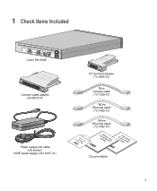
1 Check Items Included ACT LINK ETHERNET 1 ACT LINK ETHERNET 0 USB CONSOLE DC POWER INPUT Cisco PIX 506E Console cable adapter (29-0810-01) Power supply and cable (US shown) 506E power supply (341-0007-01) PC terminal adapter (74-0495-01) Blue console cable (72-1259-01) Yellow Ethernet cable (72-1482-01) ProdFuicCrteisCwcDaollPIX Yellow Ethernet cable (72-1482-01) CGoumSidapefleiatyncaend QGuuiPicdkIeXS5ta0r6tE Documentation 3
1 Check Items Included ACT LINK ETHERNET 1 ACT LINK ETHERNET 0 USB CONSOLE DC POWER INPUT Cisco PIX 506E Console cable adapter (29-0810-01) Power supply and cable (US shown) 506E power supply (341-0007-01) PC terminal adapter (74-0495-01) Blue console cable (72-1259-01) Yellow Ethernet cable (72-1482-01) ProdFuicCrteisCwcDaollPIX Yellow Ethernet cable (72-1482-01) CGoumSidapefleiatyncaend QGuuiPicdkIeXS5ta0r6tE Documentation 3
Quick Start Guide
Page 4
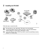
...interface, Ethernet 0, to a switch or hub. 4 Use the other network device Laptop computer Printer Yellow Ethernet cables Switch Cisco PIX 506E ACT ETHERNET 1 LINK ACT ETHERNET 0 LINK USB DC CONSOLE IPNOPWUETR Yellow Ethernet cable Power adapter Router Internet 71116 Follow these steps to connect the cables: Step 1 Step 2 Step 3 Place the chassis on a flat, stable surface. The chassis is not rack mountable. 2 Installing the PIX 506E Computer or other Ethernet cable (72-1482-01) provided to connect the inside Ethernet interface, Ethernet 1, to a DSL modem, cable modem...
...interface, Ethernet 0, to a switch or hub. 4 Use the other network device Laptop computer Printer Yellow Ethernet cables Switch Cisco PIX 506E ACT ETHERNET 1 LINK ACT ETHERNET 0 LINK USB DC CONSOLE IPNOPWUETR Yellow Ethernet cable Power adapter Router Internet 71116 Follow these steps to connect the cables: Step 1 Step 2 Step 3 Place the chassis on a flat, stable surface. The chassis is not rack mountable. 2 Installing the PIX 506E Computer or other Ethernet cable (72-1482-01) provided to connect the inside Ethernet interface, Ethernet 1, to a DSL modem, cable modem...
Quick Start Guide
Page 5
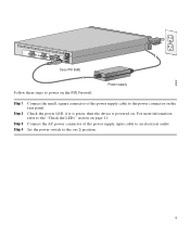
Set the power switch to an electrical outlet. Connect the AC power connector of the power supply cable to the "Check the LEDs" section on page 11. 67932 ACT LINK ETHERNET 1 ACT LINK ETHERNET 0 DC POWER USB CONSOLE INPUT DC POWER INPUT Cisco PIX 506E Follow these steps to power on the PIX Firewall: Power supply Step 1 Step 2 Step 3 Step 4 Connect the small, square connector of the power supply input cable to the on (|) position. 5 Check the power LED, if it is green, then the device is powered on the rear panel. For...
Set the power switch to an electrical outlet. Connect the AC power connector of the power supply cable to the "Check the LEDs" section on page 11. 67932 ACT LINK ETHERNET 1 ACT LINK ETHERNET 0 DC POWER USB CONSOLE INPUT DC POWER INPUT Cisco PIX 506E Follow these steps to power on the PIX Firewall: Power supply Step 1 Step 2 Step 3 Step 4 Connect the small, square connector of the power supply input cable to the on (|) position. 5 Check the power LED, if it is green, then the device is powered on the rear panel. For...
Quick Start Guide
Page 6
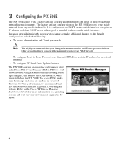
... the PIX 506E protects your web browser. The factory default configuration on the outside interface • To configure VPN and Auto Update features The PIX 506E contains an integrated configuration utility called Cisco PIX Device Manager (PDM). Refer to the Cisco PIX Device Manager Installation Guide for an outside interface to help you change or make sure JavaScript and Java are enabled in your inside interface. A default DHCP server address pool is preinstalled on operating system and web browser environments supported by PDM. 6 PDM is configured to secure...
... the PIX 506E protects your web browser. The factory default configuration on the outside interface • To configure VPN and Auto Update features The PIX 506E contains an integrated configuration utility called Cisco PIX Device Manager (PDM). Refer to the Cisco PIX Device Manager Installation Guide for an outside interface to help you change or make sure JavaScript and Java are enabled in your inside interface. A default DHCP server address pool is preinstalled on operating system and web browser environments supported by PDM. 6 PDM is configured to secure...
Quick Start Guide
Page 7
... a secure connection between your browser and the PIX Firewall that your PC has basic connectivity to connect your username or password, just press Enter. Accept the certificates and follow the instructions in the Startup Wizard. For online help, click the Help button at the bottom of the 192.168.1.0 network. Note Remember to add the "s" to the port lights up solid green. Configure your PC to use an Ethernet cable to...
... a secure connection between your browser and the PIX Firewall that your PC has basic connectivity to connect your username or password, just press Enter. Accept the certificates and follow the instructions in the Startup Wizard. For online help, click the Help button at the bottom of the 192.168.1.0 network. Note Remember to add the "s" to the port lights up solid green. Configure your PC to use an Ethernet cable to...
Quick Start Guide
Page 8
... do not have downloaded an image-not from the command line or without rebooting first. Accessing this form also requires prior registration on Cisco.com at the following website: http://www.cisco.com/cgi-bin/Software/FormManager/formgenerator.pl?pid=221&fid=324 Note If you are unable to access this form because you have your Cisco PIX Firewall 3DES upgrade document with the...
... do not have downloaded an image-not from the command line or without rebooting first. Accessing this form also requires prior registration on Cisco.com at the following website: http://www.cisco.com/cgi-bin/Software/FormManager/formgenerator.pl?pid=221&fid=324 Note If you are unable to access this form because you have your Cisco PIX Firewall 3DES upgrade document with the...
Quick Start Guide
Page 9
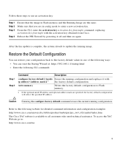
... command, replacing activation-key-four-tuple with the activation key obtained from Cisco. To access the TAC Website go to Flash memory. 1. Follow these steps to use an activation key: Step 1 Step 2 Step 3 Step 4 Ensure that you are in Flash memory and the Running Image are specified, the factory-default configuration will reflect the specified IP address. Make sure that the image in config mode to the following CLI commands: Step 1 Step 2 Command Description configure factory-default [ [address mask]] 1 the factory default configuration. Reboot the PIX Firewall...
... command, replacing activation-key-four-tuple with the activation key obtained from Cisco. To access the TAC Website go to Flash memory. 1. Follow these steps to use an activation key: Step 1 Step 2 Step 3 Step 4 Ensure that you are in Flash memory and the Running Image are specified, the factory-default configuration will reflect the specified IP address. Make sure that the image in config mode to the following CLI commands: Step 1 Step 2 Command Description configure factory-default [ [address mask]] 1 the factory default configuration. Reboot the PIX Firewall...
Quick Start Guide
Page 10
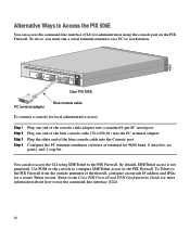
... outside IP address and IPSec for local administrative access: Step 1 Step 2 Step 3 Step 4 Plug one end of the blue console cable (72-1259-01) into the Console port. Plug the other end of the console cable adapter into a standard 9-pin PC serial port. Use PDM or the console to configure SSH/Telnet access to the PIX Firewall. Alternative Ways to Access the PIX 506E You can also access the CLI using the console port on a PC or workstation. 67935 ACT LINK ETHERNET 1 ACT LINK ETHERNET 0 DC POWER USB CONSOLE INPUT DC POWER INPUT Cisco PIX 506E...
... outside IP address and IPSec for local administrative access: Step 1 Step 2 Step 3 Step 4 Plug one end of the blue console cable (72-1259-01) into the Console port. Plug the other end of the console cable adapter into a standard 9-pin PC serial port. Use PDM or the console to configure SSH/Telnet access to the PIX Firewall. Alternative Ways to Access the PIX 506E You can also access the CLI using the console port on a PC or workstation. 67935 ACT LINK ETHERNET 1 ACT LINK ETHERNET 0 DC POWER USB CONSOLE INPUT DC POWER INPUT Cisco PIX 506E...
Quick Start Guide
Page 11
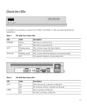
... traffic. 78186 Insert picture of 506/506E here. Table 1 PIX 506E Front Panel LEDs LED POWER ACT Network State Green Off Flashing green Off Flashing green Off Description The device is present on . No network interfaces are operating as expected (see Table 1 and Table 2), this concludes the hardware installation. The software image has been loaded. No data is present on the port. 11 ACT LINK ACT LINK ETHERNET 1 ETHERNET 0 USB CONSOLE DC POWER INPUT Table 2 LED...
... traffic. 78186 Insert picture of 506/506E here. Table 1 PIX 506E Front Panel LEDs LED POWER ACT Network State Green Off Flashing green Off Flashing green Off Description The device is present on . No network interfaces are operating as expected (see Table 1 and Table 2), this concludes the hardware installation. The software image has been loaded. No data is present on the port. 11 ACT LINK ACT LINK ETHERNET 1 ETHERNET 0 USB CONSOLE DC POWER INPUT Table 2 LED...
Quick Start Guide
Page 13
... integrated Internet application and a powerful, easy-to-use tool that provides a broad range of interactive, networked services that provides immediate, open access to Cisco information, networking solutions, services, programs, and resources at any time, from online tools by using the Cisco Technical Assistance Center (TAC) Web Site. Cisco.com registered users have complete access to the technical support resources on Cisco.com to • Streamline business processes and improve productivity •...
... integrated Internet application and a powerful, easy-to-use tool that provides a broad range of interactive, networked services that provides immediate, open access to Cisco information, networking solutions, services, programs, and resources at any time, from online tools by using the Cisco Technical Assistance Center (TAC) Web Site. Cisco.com registered users have complete access to the technical support resources on Cisco.com to • Streamline business processes and improve productivity •...

Quick Start Guide
Page 14
Cisco TAC Web Site The Cisco TAC Web Site allows you to online tools, knowledge bases, and software. If you have a valid service contract but do not have a login ID or password, go to the technical support resources on the priority of the problem and the conditions of toll-free Cisco TAC telephone numbers for example, SMARTnet, SMARTnet Onsite, or Network Supported Accounts (NSA). Which Cisco TAC resource you...
Cisco TAC Web Site The Cisco TAC Web Site allows you to online tools, knowledge bases, and software. If you have a valid service contract but do not have a login ID or password, go to the technical support resources on the priority of the problem and the conditions of toll-free Cisco TAC telephone numbers for example, SMARTnet, SMARTnet Onsite, or Network Supported Accounts (NSA). Which Cisco TAC resource you...
Quick Start Guide
Page 16
... Cisco and any other countries. The use of their respective owners. Addresses, phone numbers, and fax numbers are trademarks of Cisco Systems, Inc.; CCIP, the Cisco Arrow logo, the Cisco Powered Network mark, the Cisco Systems Verified logo, Cisco Unity, Follow Me Browsing, FormShare, iQ Breakthrough, iQ Expertise, iQ FastTrack, the iQ logo, iQ Net Readiness Scorecard, Networking Academy, ScriptShare, SMARTnet, TransPath, and Voice LAN are listed...
... Cisco and any other countries. The use of their respective owners. Addresses, phone numbers, and fax numbers are trademarks of Cisco Systems, Inc.; CCIP, the Cisco Arrow logo, the Cisco Powered Network mark, the Cisco Systems Verified logo, Cisco Unity, Follow Me Browsing, FormShare, iQ Breakthrough, iQ Expertise, iQ FastTrack, the iQ logo, iQ Net Readiness Scorecard, Networking Academy, ScriptShare, SMARTnet, TransPath, and Voice LAN are listed...
User Guide
Page 1
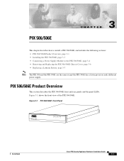
.../506E Front Panel 67945 POWER ACT NETWORK CISCO PIX 506E F I R E WA L L 78-15170-02 Cisco PIX Security Appliance Hardware Installation Guide 3-1 PIX 506/506E CH A P T E R 3 This chapter describes how to install a PIX 506/506E, and includes the following sections: • PIX 506/506E Product Overview, page 3-1 • Installing the PIX 506/506E, page 3-3 • Connecting a Power Supply Module to the PIX 506/506E, page 3-4 • Removing and Replacing the PIX 506/506E Chassis Cover, page 3-6 • Replacing a Lithium Battery, page 3-7 Note The PIX 506 and the PIX 506E...
.../506E Front Panel 67945 POWER ACT NETWORK CISCO PIX 506E F I R E WA L L 78-15170-02 Cisco PIX Security Appliance Hardware Installation Guide 3-1 PIX 506/506E CH A P T E R 3 This chapter describes how to install a PIX 506/506E, and includes the following sections: • PIX 506/506E Product Overview, page 3-1 • Installing the PIX 506/506E, page 3-3 • Connecting a Power Supply Module to the PIX 506/506E, page 3-4 • Removing and Replacing the PIX 506/506E Chassis Cover, page 3-6 • Replacing a Lithium Battery, page 3-7 Note The PIX 506 and the PIX 506E...
User Guide
Page 2
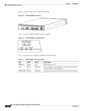
Cisco PIX Security Appliance Hardware Installation Guide 3-2 78-15170-02 Figure 3-2 PIX 506/506E Rear Panel Chapter 3 PIX 506/506E 67947 ACT LINK ETHERNET 1 ACT LINK ETHERNET 0 USB CONSOLE DC POWER INPUT Figure 3-3 shows the PIX 506/506E front panel LEDs. Table 3-1 PIX 506/506E Front Panel LEDs LED POWER ACT Color Green Green NETWORK Green State On Flashing Flashing Description The unit has power. On when at least one network interface is passing traffic. Active indicator-On when the software image has been loaded on...
Cisco PIX Security Appliance Hardware Installation Guide 3-2 78-15170-02 Figure 3-2 PIX 506/506E Rear Panel Chapter 3 PIX 506/506E 67947 ACT LINK ETHERNET 1 ACT LINK ETHERNET 0 USB CONSOLE DC POWER INPUT Figure 3-3 shows the PIX 506/506E front panel LEDs. Table 3-1 PIX 506/506E Front Panel LEDs LED POWER ACT Color Green Green NETWORK Green State On Flashing Flashing Description The unit has power. On when at least one network interface is passing traffic. Active indicator-On when the software image has been loaded on...
User Guide
Page 3
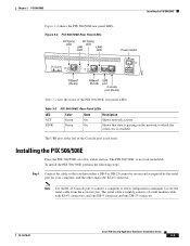
... Cisco PIX Security Appliance Hardware Installation Guide 3-3 The PIX 506/506E is attached. To install the PIX 506/506E, perform the following steps: Step 1 Connect the cable so that data is passing on a flat, stable surface. The serial cable assembly consists of a null modem cable with RJ-45 connectors, and one DB-9 connector and one end as required by the serial port for your computer, and the other end is not used. The USB port...
... Cisco PIX Security Appliance Hardware Installation Guide 3-3 The PIX 506/506E is attached. To install the PIX 506/506E, perform the following steps: Step 1 Connect the cable so that data is passing on a flat, stable surface. The serial cable assembly consists of a null modem cable with RJ-45 connectors, and one DB-9 connector and one end as required by the serial port for your computer, and the other end is not used. The USB port...
User Guide
Page 4
...the power supply module to the power supply. Figure 3-5 PIX 506/506E Serial Console Cable ACT LINK ETHERNET 1 ACT LINK ETHERNET 0 USB CONSOLE DC POWER INPUT Console port (RJ-45) RJ-45 to DB-9 or DB-25 serial cable (null-modem) Computer serial port DB-9 or DB-25 38853 Step 3 Connect the inside or outside network cable to the remaining Ethernet port. Use this information in conjunction with the Regulatory Compliance and Safety Information document. Cisco PIX Security Appliance Hardware Installation Guide 3-4 78-15170-02 Power is supplied to the PIX 506/506E by connecting...
...the power supply module to the power supply. Figure 3-5 PIX 506/506E Serial Console Cable ACT LINK ETHERNET 1 ACT LINK ETHERNET 0 USB CONSOLE DC POWER INPUT Console port (RJ-45) RJ-45 to DB-9 or DB-25 serial cable (null-modem) Computer serial port DB-9 or DB-25 38853 Step 3 Connect the inside or outside network cable to the remaining Ethernet port. Use this information in conjunction with the Regulatory Compliance and Safety Information document. Cisco PIX Security Appliance Hardware Installation Guide 3-4 78-15170-02 Power is supplied to the PIX 506/506E by connecting...
User Guide
Page 5
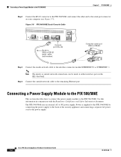
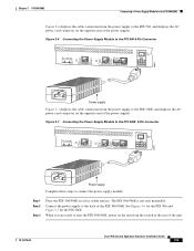
... 3 PIX 506/506E Connecting a Power Supply Module to the PIX 506/506E Figure 3-6 displays the cable connection from the switch at the rear of the unit. 78-15170-02 Cisco PIX Security Appliance Hardware Installation Guide 3-5 Figure 3-6 Connecting the Power Supply Module to the PIX 506 6-Pin Connector ACT LINK ETHERNET 1 ACT LINK ETHERNET 0 USB CONSOLE DC POWER INPUT 38854 Power supply Figure 3-7 displays the cable connection from the power supply to connect the power supply module: Step 1 Step 2 Step 3 Place the PIX 506/506E on the unit from the power supply to the PIX 506...
... 3 PIX 506/506E Connecting a Power Supply Module to the PIX 506/506E Figure 3-6 displays the cable connection from the switch at the rear of the unit. 78-15170-02 Cisco PIX Security Appliance Hardware Installation Guide 3-5 Figure 3-6 Connecting the Power Supply Module to the PIX 506 6-Pin Connector ACT LINK ETHERNET 1 ACT LINK ETHERNET 0 USB CONSOLE DC POWER INPUT 38854 Power supply Figure 3-7 displays the cable connection from the power supply to connect the power supply module: Step 1 Step 2 Step 3 Place the PIX 506/506E on the unit from the power supply to the PIX 506...
User Guide
Page 6
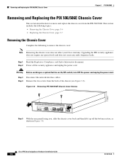
... affect your Cisco warranty. Step 2 Power off the bottom section, as shown in Figure 3-8. Step 4 Remove the two screws from the PIX 506/506E. Figure 3-8 Removing PIX 506/506E Chassis Cover Screws 119681 ACT LINK ETHERNET 1 ACT LINK ETHERNET 0 USB CONSOLE DC POWER INPUT Step 5 With the rear panel facing you, slide the chassis cover back and then lift it up off the security appliance and unplug the power cord. Upgrading the PIX security appliance does...
... affect your Cisco warranty. Step 2 Power off the bottom section, as shown in Figure 3-8. Step 4 Remove the two screws from the PIX 506/506E. Figure 3-8 Removing PIX 506/506E Chassis Cover Screws 119681 ACT LINK ETHERNET 1 ACT LINK ETHERNET 0 USB CONSOLE DC POWER INPUT Step 5 With the rear panel facing you, slide the chassis cover back and then lift it up off the security appliance and unplug the power cord. Upgrading the PIX security appliance does...
User Guide
Page 7
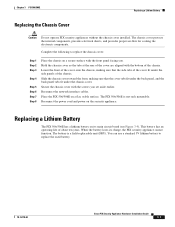
.... Place the PIX 506/506E on a secure surface with the screws you . Replacing a Lithium Battery The PIX 506/506E has a lithium battery on the security appliance. You can use a standard 3V lithium battery to replace the chassis cover: Step 1 Step 2 Step 3 Step 4 Step 5 Step 6 Step 7 Step 8 Place the chassis on a flat, stable surface. Secure the chassis cover with the front panel facing you set aside earlier. Reconnect the network interface cables. This battery...
.... Place the PIX 506/506E on a secure surface with the screws you . Replacing a Lithium Battery The PIX 506/506E has a lithium battery on the security appliance. You can use a standard 3V lithium battery to replace the chassis cover: Step 1 Step 2 Step 3 Step 4 Step 5 Step 6 Step 7 Step 8 Place the chassis on a flat, stable surface. Secure the chassis cover with the front panel facing you set aside earlier. Reconnect the network interface cables. This battery...


