Quick Start Guide
Page 2
... console port for administrative access • Front panel LEDs for appliance and link status • 20-Mbps cleartext firewall throughput • 16 Mbps PIX 506E VPN throughput (3DES/SHA1) • Supports PIX Firewall software Version 5.3 and higher, a secure, purpose-built embedded operating system • Includes plug-and-play default configuration for simplified installation • Includes Cisco PIX Device...
... console port for administrative access • Front panel LEDs for appliance and link status • 20-Mbps cleartext firewall throughput • 16 Mbps PIX 506E VPN throughput (3DES/SHA1) • Supports PIX Firewall software Version 5.3 and higher, a secure, purpose-built embedded operating system • Includes plug-and-play default configuration for simplified installation • Includes Cisco PIX Device...
Quick Start Guide
Page 3
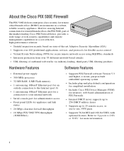
1 Check Items Included ACT LINK ETHERNET 1 ACT LINK ETHERNET 0 USB CONSOLE DC POWER INPUT Cisco PIX 506E Console cable adapter (29-0810-01) Power supply and cable (US shown) 506E power supply (341-0007-01) PC terminal adapter (74-0495-01) Blue console cable (72-1259-01) Yellow Ethernet cable (72-1482-01) ProdFuicCrteisCwcDaollPIX Yellow Ethernet cable (72-1482-01) CGoumSidapefleiatyncaend QGuuiPicdkIeXS5ta0r6tE Documentation 3
1 Check Items Included ACT LINK ETHERNET 1 ACT LINK ETHERNET 0 USB CONSOLE DC POWER INPUT Cisco PIX 506E Console cable adapter (29-0810-01) Power supply and cable (US shown) 506E power supply (341-0007-01) PC terminal adapter (74-0495-01) Blue console cable (72-1259-01) Yellow Ethernet cable (72-1482-01) ProdFuicCrteisCwcDaollPIX Yellow Ethernet cable (72-1482-01) CGoumSidapefleiatyncaend QGuuiPicdkIeXS5ta0r6tE Documentation 3
Quick Start Guide
Page 4
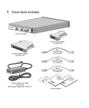
Use the other network device Laptop computer Printer Yellow Ethernet cables Switch Cisco PIX 506E ACT ETHERNET 1 LINK ACT ETHERNET 0 LINK USB DC CONSOLE IPNOPWUETR Yellow Ethernet cable Power adapter Router Internet 71116 Follow these steps to connect the cables: Step 1 Step 2 Step 3 Place the ... (72-1482-01) provided to connect the outside Ethernet interface, Ethernet 0, to a DSL modem, cable modem, or router. 2 Installing the PIX 506E Computer or other Ethernet cable (72-1482-01) provided to connect the inside Ethernet interface, Ethernet 1, to a switch or hub. 4
Use the other network device Laptop computer Printer Yellow Ethernet cables Switch Cisco PIX 506E ACT ETHERNET 1 LINK ACT ETHERNET 0 LINK USB DC CONSOLE IPNOPWUETR Yellow Ethernet cable Power adapter Router Internet 71116 Follow these steps to connect the cables: Step 1 Step 2 Step 3 Place the ... (72-1482-01) provided to connect the outside Ethernet interface, Ethernet 0, to a DSL modem, cable modem, or router. 2 Installing the PIX 506E Computer or other Ethernet cable (72-1482-01) provided to connect the inside Ethernet interface, Ethernet 1, to a switch or hub. 4
Quick Start Guide
Page 5
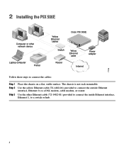
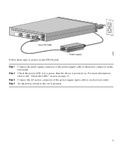
67932 ACT LINK ETHERNET 1 ACT LINK ETHERNET 0 DC POWER USB CONSOLE INPUT DC POWER INPUT Cisco PIX 506E Follow these steps to power on the PIX Firewall: Power supply Step 1 Step 2 Step 3 Step 4 Connect the small, square connector of the power supply input cable to an electrical outlet. Set the power ...
67932 ACT LINK ETHERNET 1 ACT LINK ETHERNET 0 DC POWER USB CONSOLE INPUT DC POWER INPUT Cisco PIX 506E Follow these steps to power on the PIX Firewall: Power supply Step 1 Step 2 Step 3 Step 4 Connect the small, square connector of the power supply input cable to an electrical outlet. Set the power ...
Quick Start Guide
Page 10
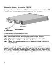
... interface (CLI). 10 Alternative Ways to Access the PIX 506E You can also access the CLI using the console port on a PC or workstation. 67935 ACT LINK ETHERNET 1 ACT LINK ETHERNET 0 DC POWER USB CONSOLE INPUT DC POWER INPUT Cisco PIX 506E PC terminal adapter Blue console cable To connect a console for a secure Telnet session. To do so, you must...
... interface (CLI). 10 Alternative Ways to Access the PIX 506E You can also access the CLI using the console port on a PC or workstation. 67935 ACT LINK ETHERNET 1 ACT LINK ETHERNET 0 DC POWER USB CONSOLE INPUT DC POWER INPUT Cisco PIX 506E PC terminal adapter Blue console cable To connect a console for a secure Telnet session. To do so, you must...
Quick Start Guide
Page 11
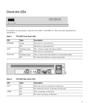
Check the LEDs POWER ACT NETWORK CISCO PIX 506E F I R E WA L L 67933 If all LEDs are passing traffic. The software image has been loaded. The device is passing on the port. One or more network ... activity is passing on the port. ACT LINK ACT LINK ETHERNET 1 ETHERNET 0 USB CONSOLE DC POWER INPUT Table 2 LED ACT LINK PIX 506E Rear Panel LEDs State On Off On Off Description Network activity is powered on the port. Table 1 PIX 506E Front Panel LEDs LED POWER ACT Network State Green Off Flashing green Off...
Check the LEDs POWER ACT NETWORK CISCO PIX 506E F I R E WA L L 67933 If all LEDs are passing traffic. The software image has been loaded. The device is passing on the port. One or more network ... activity is passing on the port. ACT LINK ACT LINK ETHERNET 1 ETHERNET 0 USB CONSOLE DC POWER INPUT Table 2 LED ACT LINK PIX 506E Rear Panel LEDs State On Off On Off Description Network activity is powered on the port. Table 1 PIX 506E Front Panel LEDs LED POWER ACT Network State Green Off Flashing green Off...
User Guide
Page 2
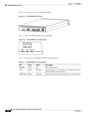
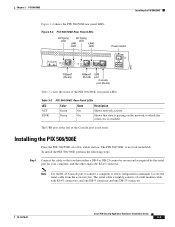
... NETWORK Green State On Flashing Flashing Description The unit has power. PIX 506/506E Product Overview Figure 3-2 shows the rear view of the PIX 506/506E front panel LEDs. Cisco PIX Security Appliance Hardware Installation Guide 3-2 78-15170-02 On when at least one...security appliance. Figure 3-3 PIX 506/506E Front Panel LEDs POWER ACT NETWORK 25735 Table 3-1 lists the states of the PIX 506/506E. Figure 3-2 PIX 506/506E Rear Panel Chapter 3 PIX 506/506E 67947 ACT LINK ETHERNET 1 ACT LINK ETHERNET 0 USB CONSOLE DC POWER INPUT Figure 3-3 shows the PIX 506/506E...
... NETWORK Green State On Flashing Flashing Description The unit has power. PIX 506/506E Product Overview Figure 3-2 shows the rear view of the PIX 506/506E front panel LEDs. Cisco PIX Security Appliance Hardware Installation Guide 3-2 78-15170-02 On when at least one...security appliance. Figure 3-3 PIX 506/506E Front Panel LEDs POWER ACT NETWORK 25735 Table 3-1 lists the states of the PIX 506/506E. Figure 3-2 PIX 506/506E Rear Panel Chapter 3 PIX 506/506E 67947 ACT LINK ETHERNET 1 ACT LINK ETHERNET 0 USB CONSOLE DC POWER INPUT Figure 3-3 shows the PIX 506/506E...
User Guide
Page 3
... passing on one DB-25 connector. 78-15170-02 Cisco PIX Security Appliance Hardware Installation Guide 3-3 The USB port at the left of the Console port is not rack mountable. The serial cable assembly consists of the PIX 506/506E rear panel LEDs. Note Use the RJ-45 Console port to connect a computer to which the connector is...
... passing on one DB-25 connector. 78-15170-02 Cisco PIX Security Appliance Hardware Installation Guide 3-3 The USB port at the left of the Console port is not rack mountable. The serial cable assembly consists of the PIX 506/506E rear panel LEDs. Note Use the RJ-45 Console port to connect a computer to which the connector is...
User Guide
Page 4
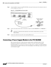
... to the back of the security appliance and connecting a separate AC power cord to DC power supply. Cisco PIX Security Appliance Hardware Installation Guide 3-4 78-15170-02 The PIX 506/506E uses an external AC to the power supply. Figure 3-5 PIX 506/506E Serial Console Cable ACT LINK ETHERNET 1 ACT LINK ETHERNET 0 USB CONSOLE DC POWER INPUT Console port (RJ-45) RJ-45...
... to the back of the security appliance and connecting a separate AC power cord to DC power supply. Cisco PIX Security Appliance Hardware Installation Guide 3-4 78-15170-02 The PIX 506/506E uses an external AC to the power supply. Figure 3-5 PIX 506/506E Serial Console Cable ACT LINK ETHERNET 1 ACT LINK ETHERNET 0 USB CONSOLE DC POWER INPUT Console port (RJ-45) RJ-45...
User Guide
Page 5
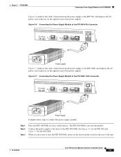
... 1 ACT LINK ETHERNET 0 USB CONSOLE DC POWER INPUT 38854 Power supply Figure 3-7 displays the cable connection from the switch at the opposite end of the unit. 78-15170-02 Cisco PIX Security Appliance Hardware Installation Guide 3-5 When you are ready to start the PIX 506/506E, power on a flat, stable surface. The PIX 506/506E is not rack mountable...
... 1 ACT LINK ETHERNET 0 USB CONSOLE DC POWER INPUT 38854 Power supply Figure 3-7 displays the cable connection from the switch at the opposite end of the unit. 78-15170-02 Cisco PIX Security Appliance Hardware Installation Guide 3-5 When you are ready to start the PIX 506/506E, power on a flat, stable surface. The PIX 506/506E is not rack mountable...
User Guide
Page 6
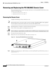
... screws from the PIX 506/506E. Upgrading the PIX security appliance does not require any special tools and does not create any radio frequency leaks. Figure 3-8 Removing PIX 506/506E Chassis Cover Screws 119681 ACT LINK ETHERNET 1 ACT LINK ETHERNET 0 USB CONSOLE DC POWER INPUT ...(see Figure 3-8). Cisco PIX Security Appliance Hardware Installation Guide 3-6 78-15170-02 Step 1 Read the Regulatory Compliance and Safety Information document. Removing and Replacing the PIX 506/506E Chassis Cover Chapter 3 PIX 506/506E Removing and Replacing the PIX 506/506E Chassis Cover This section...
... screws from the PIX 506/506E. Upgrading the PIX security appliance does not require any special tools and does not create any radio frequency leaks. Figure 3-8 Removing PIX 506/506E Chassis Cover Screws 119681 ACT LINK ETHERNET 1 ACT LINK ETHERNET 0 USB CONSOLE DC POWER INPUT ...(see Figure 3-8). Cisco PIX Security Appliance Hardware Installation Guide 3-6 78-15170-02 Step 1 Read the Regulatory Compliance and Safety Information document. Removing and Replacing the PIX 506/506E Chassis Cover Chapter 3 PIX 506/506E Removing and Replacing the PIX 506/506E Chassis Cover This section...
