
Installation Guide
Page 4
...the Cable Guide (Optional) 3-8 Installing the Catalyst 4948E-F Switch Chassis with the Optional Panduit Air Duct Kit 3-9 Installing the System Ground 3-10 Connecting Power to the Switch 3-12 Connecting AC Source Power to the Switch 3-12 Connecting DC Source Power to the Switch 3-13 Attaching the Interface Cables 3-15 ...Cables 3-16 Connecting to the Ethernet Management Port 3-20 Connecting to the Console Port 3-20 Powering Up the Switch 3-21 Starting the Terminal-Emulation Software 3-21 Powering Up the Switch 3-21 Catalyst 4948E and Catalyst 4948E-F Switch Installation Guide iv OL-21561-02
...the Cable Guide (Optional) 3-8 Installing the Catalyst 4948E-F Switch Chassis with the Optional Panduit Air Duct Kit 3-9 Installing the System Ground 3-10 Connecting Power to the Switch 3-12 Connecting AC Source Power to the Switch 3-12 Connecting DC Source Power to the Switch 3-13 Attaching the Interface Cables 3-15 ...Cables 3-16 Connecting to the Ethernet Management Port 3-20 Connecting to the Console Port 3-20 Powering Up the Switch 3-21 Starting the Terminal-Emulation Software 3-21 Powering Up the Switch 3-21 Catalyst 4948E and Catalyst 4948E-F Switch Installation Guide iv OL-21561-02
Installation Guide
Page 5
... Power Supply 4-8 Installing the AC-Input Power Supply 4-9 Removing and Installing the Fan Tray 4-10 Required Tools 4-10 Removing the Fan Tray 4-10 Installing the Fan Tray 4-11 Power Supply Specifications A-1 300 W AC-Input Power Supply (PWR...10 Ethernet Management Port B-11 Cables and Adapters B-11 Rollover Cable B-11 Rollover Cable RJ-45 to DB-9 Adapter (For Connecting to a PC) B-12 Troubleshooting the Installation C-1 Getting Started C-2 Problem Solving to the System Component Level C-2 Identifying Startup Problems C-2 LED Readings C-3 OL-21561-02 Catalyst 4948E and Catalyst 4948E-F Switch...
... Power Supply 4-8 Installing the AC-Input Power Supply 4-9 Removing and Installing the Fan Tray 4-10 Required Tools 4-10 Removing the Fan Tray 4-10 Installing the Fan Tray 4-11 Power Supply Specifications A-1 300 W AC-Input Power Supply (PWR...10 Ethernet Management Port B-11 Cables and Adapters B-11 Rollover Cable B-11 Rollover Cable RJ-45 to DB-9 Adapter (For Connecting to a PC) B-12 Troubleshooting the Installation C-1 Getting Started C-2 Problem Solving to the System Component Level C-2 Identifying Startup Problems C-2 LED Readings C-3 OL-21561-02 Catalyst 4948E and Catalyst 4948E-F Switch...
Installation Guide
Page 6
...43-Jewelry Removal Warning D-5 Statement 48-Stacking the Chassis Warning D-8 Statement 171-Ethernet Cable Shielding in Offices D-9 Statement 258-Fan Tray Removal Warning D-10 Statement 322-DC Power Off Warning D-11 Statement 1001-Work During Lightning Activity D-12 Statement 1003-DC Power Disconnection D-13 Statement 1004-Installation Instructions ...Equipment Bonding Networks D-42 Statement 7014-Installation Location D-42 Statement 7015-Equipment Bonding and Grounding D-42 Statement 7016-Battery Return Conductor D-42 Catalyst 4948E and Catalyst 4948E-F Switch Installation Guide vi OL-21561-02
...43-Jewelry Removal Warning D-5 Statement 48-Stacking the Chassis Warning D-8 Statement 171-Ethernet Cable Shielding in Offices D-9 Statement 258-Fan Tray Removal Warning D-10 Statement 322-DC Power Off Warning D-11 Statement 1001-Work During Lightning Activity D-12 Statement 1003-DC Power Disconnection D-13 Statement 1004-Installation Instructions ...Equipment Bonding Networks D-42 Statement 7014-Installation Location D-42 Statement 7015-Equipment Bonding and Grounding D-42 Statement 7016-Battery Return Conductor D-42 Catalyst 4948E and Catalyst 4948E-F Switch Installation Guide vi OL-21561-02
Installation Guide
Page 17
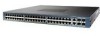
... rear view of the chassis. Figure 1-1 shows the front view of both chassis with 48 10/100/1000 downlink ports and 4 1-GB or 10-GB uplink ports. Tip For additional information about the Cisco Catalyst 4948E and the Catalyst 4948E-F switches (including configuration examples and troubleshooting information), see the documents listed on this page: http://www...
... rear view of the chassis. Figure 1-1 shows the front view of both chassis with 48 10/100/1000 downlink ports and 4 1-GB or 10-GB uplink ports. Tip For additional information about the Cisco Catalyst 4948E and the Catalyst 4948E-F switches (including configuration examples and troubleshooting information), see the documents listed on this page: http://www...
Installation Guide
Page 20
... installed. Additional information including a connector pinout table is not provided in the port socket. This port can be ordered as an option. • The Catalyst 4948E switch provides a 10/100/1000 RJ-45 port Ethernet Management port that provides connectivity between the multishelf system and networks from which system management is not installed...
... installed. Additional information including a connector pinout table is not provided in the port socket. This port can be ordered as an option. • The Catalyst 4948E switch provides a 10/100/1000 RJ-45 port Ethernet Management port that provides connectivity between the multishelf system and networks from which system management is not installed...
Installation Guide
Page 23
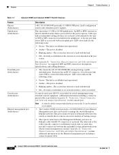
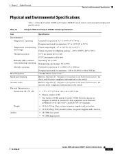
.... • 28 CFM (low speed) • 44 CFM (high speed) OL-21561-02 Catalyst 4948E and Catalyst 4948E-F Switch Installation Guide 1-7 Table 1-2 Catalyst 4948E and Catalyst 4948E-F Switch Specifications Item Environmental Temperature, operating Temperature, nonoperating and storage Thermal transition Humidity (RH), ambient (noncondensing)...20° to Appendix D, "Regulatory Compliance and Safety Information" for shock and vibration compliance information for operation: -200 to 10,000 ft (-60 to 3000 m) 1364 BTU/hour (worst case) Refer to 65°C) Chassis in standard 19-inch ...
.... • 28 CFM (low speed) • 44 CFM (high speed) OL-21561-02 Catalyst 4948E and Catalyst 4948E-F Switch Installation Guide 1-7 Table 1-2 Catalyst 4948E and Catalyst 4948E-F Switch Specifications Item Environmental Temperature, operating Temperature, nonoperating and storage Thermal transition Humidity (RH), ambient (noncondensing)...20° to Appendix D, "Regulatory Compliance and Safety Information" for shock and vibration compliance information for operation: -200 to 10,000 ft (-60 to 3000 m) 1364 BTU/hour (worst case) Refer to 65°C) Chassis in standard 19-inch ...
Installation Guide
Page 26
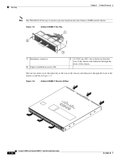
The fan tray draws in Figure 1-6. Figure 1-6 Catalyst 4948E-F Chassis Airflow 281614 1-10 Catalyst 4948E and Catalyst 4948E-F Switch Installation Guide OL-21561-02 Figure 1-5 Catalyst 4948E-F Fan Tray 1 2 278085 3 1 Backplane connector 2 Captive installation screw (2X) 3 12 VDC fan (4X). Air is keyed to prevent insertion into the Catalyst 4948E switch chassis. Fan Tray Chapter 1 Product Overview Note The...
The fan tray draws in Figure 1-6. Figure 1-6 Catalyst 4948E-F Chassis Airflow 281614 1-10 Catalyst 4948E and Catalyst 4948E-F Switch Installation Guide OL-21561-02 Figure 1-5 Catalyst 4948E-F Fan Tray 1 2 278085 3 1 Backplane connector 2 Captive installation screw (2X) 3 12 VDC fan (4X). Air is keyed to prevent insertion into the Catalyst 4948E switch chassis. Fan Tray Chapter 1 Product Overview Note The...
Installation Guide
Page 27
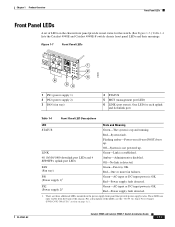
... the LEDs, see the "300 W AC-Input Power Supply (PWR-C49E-300AC-R)" section on the power supply front panel that provide power supply status. Catalyst 4948E and Catalyst 4948E-F Switch Installation Guide 1-11 Figure 1-7 Front Panel LEDs OL-21561-02 1 2 3 6 54 1 PS1 (power supply 1) 2 PS2 (power supply 2) 3 FAN (fan...LINK Green-Link is not powered up . There are only visible from the back of the chassis. Off-System is established. 48 10/100/1000 downlink port LEDs and 4 SFP/SFP+ uplink port LEDs Amber-Administrative disabled. Red-System fault. Flashing amber-Power-on the...
... the LEDs, see the "300 W AC-Input Power Supply (PWR-C49E-300AC-R)" section on the power supply front panel that provide power supply status. Catalyst 4948E and Catalyst 4948E-F Switch Installation Guide 1-11 Figure 1-7 Front Panel LEDs OL-21561-02 1 2 3 6 54 1 PS1 (power supply 1) 2 PS2 (power supply 2) 3 FAN (fan...LINK Green-Link is not powered up . There are only visible from the back of the chassis. Off-System is established. 48 10/100/1000 downlink port LEDs and 4 SFP/SFP+ uplink port LEDs Amber-Administrative disabled. Red-System fault. Flashing amber-Power-on the...
Installation Guide
Page 30
... security. Ensure that the shelf is constructed to the switch Before rack-mounting the switch, ensure the following situations: • Racks with Electricity, page 2-9 • Preventing Electrostatic Discharge Damage, page 2-10 Rack-Mounting Guidelines A rack-mount kit (69-2037-... only unit in a standard 19-inch (48.3 cm) equipment rack. and rear-mounting strips, must have sufficient vertical clearance to install your Catalyst 4948E or Catalyst 4948E-F switch: • Rack-Mounting Guidelines, page 2-2 • Temperature, page 2-3 • Air Flow, page 2-4 • Humidity, page 2-5...
... security. Ensure that the shelf is constructed to the switch Before rack-mounting the switch, ensure the following situations: • Racks with Electricity, page 2-9 • Preventing Electrostatic Discharge Damage, page 2-10 Rack-Mounting Guidelines A rack-mount kit (69-2037-... only unit in a standard 19-inch (48.3 cm) equipment rack. and rear-mounting strips, must have sufficient vertical clearance to install your Catalyst 4948E or Catalyst 4948E-F switch: • Rack-Mounting Guidelines, page 2-2 • Temperature, page 2-3 • Air Flow, page 2-4 • Humidity, page 2-5...
Installation Guide
Page 31
... C). Adequate ventilation is particularly important at high altitudes where the air is operating in an environment no colder than 50°F (10°C) or hotter than the ambient room temperature. - Ensure that the chassis has adequate ventilation. • Use proper air circulation ... sunlight, particularly in the chassis at the back of clearance behind the rack for maintenance. OL-21561-02 Catalyst 4948E and Catalyst 4948E-F Switch Installation Guide 2-3 Ensure that are susceptable to higher ambient air temperatures due to avoid disconnecting cables unnecessarily for ...
... C). Adequate ventilation is particularly important at high altitudes where the air is operating in an environment no colder than 50°F (10°C) or hotter than the ambient room temperature. - Ensure that the chassis has adequate ventilation. • Use proper air circulation ... sunlight, particularly in the chassis at the back of clearance behind the rack for maintenance. OL-21561-02 Catalyst 4948E and Catalyst 4948E-F Switch Installation Guide 2-3 Ensure that are susceptable to higher ambient air temperatures due to avoid disconnecting cables unnecessarily for ...
Installation Guide
Page 32
... at 131°F (55°C) generating a major alarm. If the difference in air temperature exceeds 10°C, there is sufficient airflow in the rack. - Air Flow The Catalyst 4948E and Catalyst 4948E-F switches are installing your Catalyst 4948E or Catalyst 4948E-F switch chassis in the hot exhaust air to overheat and fail. If the ambient intake air...
... at 131°F (55°C) generating a major alarm. If the difference in air temperature exceeds 10°C, there is sufficient airflow in the rack. - Air Flow The Catalyst 4948E and Catalyst 4948E-F switches are installing your Catalyst 4948E or Catalyst 4948E-F switch chassis in the hot exhaust air to overheat and fail. If the ambient intake air...
Installation Guide
Page 33
... Fans cool the power supplies and the system components by heat during the colder months usually maintain an acceptable level of 10 percent per hour. This moisture can be installed along with a humidity gradation of humidity for system equipment. Extreme moisture ...; International Electrotechnical Commission (IEC) IP-20 OL-21561-02 Catalyst 4948E and Catalyst 4948E-F Switch Installation Guide 2-5 Each system is rated to operate at 8 to 80 percent relative humidity, with the Catalyst 4948E-F chassis to extend the switch chassis air intake to the cold isle at high altitude (...
... Fans cool the power supplies and the system components by heat during the colder months usually maintain an acceptable level of 10 percent per hour. This moisture can be installed along with a humidity gradation of humidity for system equipment. Extreme moisture ...; International Electrotechnical Commission (IEC) IP-20 OL-21561-02 Catalyst 4948E and Catalyst 4948E-F Switch Installation Guide 2-5 Each system is rated to operate at 8 to 80 percent relative humidity, with the Catalyst 4948E-F chassis to extend the switch chassis air intake to the cold isle at high altitude (...
Installation Guide
Page 34
... new cable runs) to a suitable and safe earth ground before connecting them to appear on the system monitor. Catalyst 4948E and Catalyst 4948E-F Switch Installation Guide 2-6 OL-21561-02 The Federal Communications Commission (FCC) publishes specific regulations to other devices through the ... connectors is a gradual process that the screws on all peripheral cable connectors are run for any EMI with a frequency above 10 kilohertz (kHz). The oil from extreme temperatures and moist, salty environments. Electromagnetic and Radio Frequency Interference Electromagnetic interference (EMI) ...
... new cable runs) to a suitable and safe earth ground before connecting them to appear on the system monitor. Catalyst 4948E and Catalyst 4948E-F Switch Installation Guide 2-6 OL-21561-02 The Federal Communications Commission (FCC) publishes specific regulations to other devices through the ... connectors is a gradual process that the screws on all peripheral cable connectors are run for any EMI with a frequency above 10 kilohertz (kHz). The oil from extreme temperatures and moist, salty environments. Electromagnetic and Radio Frequency Interference Electromagnetic interference (EMI) ...
Installation Guide
Page 38
.... Modules consist of printed circuit boards that they are intended for Installation • If any of power source required, consult the Cisco Technical Assistance Center or a local electrician. • Use approved power cables only. Preventing Electrostatic Discharge Damage Electrostatic discharge (ESD) damage...that are rated for the product and for site modifications. If you must install the system ground. 2-10 Catalyst 4948E and Catalyst 4948E-F Switch Installation Guide OL-21561-02 These power cables are not sure of the type of the following conditions occur, contact ...
.... Modules consist of printed circuit boards that they are intended for Installation • If any of power source required, consult the Cisco Technical Assistance Center or a local electrician. • Use approved power cables only. Preventing Electrostatic Discharge Damage Electrostatic discharge (ESD) damage...that are rated for the product and for site modifications. If you must install the system ground. 2-10 Catalyst 4948E and Catalyst 4948E-F Switch Installation Guide OL-21561-02 These power cables are not sure of the type of the following conditions occur, contact ...
Installation Guide
Page 39
... on the ESD wrist strap and momentarily touch the clip to the ground lug screw as follows: a. OL-21561-02 Catalyst 4948E and Catalyst 4948E-F Switch Installation Guide 2-11 Note The spring clip jaws do this, your wrist and tighten the strap so that any built-up...breaker. • To prevent a loss of input power, be between 1 and 10 megohm (Mohm). If you may decide to use an uninterruptible power supply (UPS) to your bare skin. Chapter 2 Preparing for the switch installation, follow these general requirements: • In systems configured with two power supplies,...
... on the ESD wrist strap and momentarily touch the clip to the ground lug screw as follows: a. OL-21561-02 Catalyst 4948E and Catalyst 4948E-F Switch Installation Guide 2-11 Note The spring clip jaws do this, your wrist and tighten the strap so that any built-up...breaker. • To prevent a loss of input power, be between 1 and 10 megohm (Mohm). If you may decide to use an uninterruptible power supply (UPS) to your bare skin. Chapter 2 Preparing for the switch installation, follow these general requirements: • In systems configured with two power supplies,...
Installation Guide
Page 43
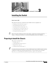
...-Mounting the Chassis, page 3-5 • Installing the System Ground, page 3-10 • Connecting Power to the Switch, page 3-12 • Attaching the Interface Cables, page 3-15 • Powering Up the Switch, page 3-21 Note Before starting the installation procedures in this chapter, complete ..., page 3-4 • Required Tools, page 3-4 • Lifting the Chassis Safely, page 3-5 Tip For additional information about the Cisco Catalyst 4948E and the Catalyst 4948E-F switches (including configuration examples and troubleshooting information), see the documents listed on this page: http://www...
...-Mounting the Chassis, page 3-5 • Installing the System Ground, page 3-10 • Connecting Power to the Switch, page 3-12 • Attaching the Interface Cables, page 3-15 • Powering Up the Switch, page 3-21 Note Before starting the installation procedures in this chapter, complete ..., page 3-4 • Required Tools, page 3-4 • Lifting the Chassis Safely, page 3-5 Tip For additional information about the Cisco Catalyst 4948E and the Catalyst 4948E-F switches (including configuration examples and troubleshooting information), see the documents listed on this page: http://www...
Installation Guide
Page 46
...-on ring connectors (the required size and style is missing or damaged, contact your Cisco representative or reseller for attaching the brackets to a rack - It can ordered as an option. Four 12-...24 x 3/4-inch and four 10-32 x 3/4-inch Phillips machine screws for damage. Preparing to Install the Chassis Chapter 3 Installing the Switch Verifying Package Contents Carefully remove the chassis and accessory kit from ... electrical codes) • Wire-stripping tool • Crimping tool Catalyst 4948E and Catalyst 4948E-F Switch Installation Guide 3-4 OL-21561-02
...-on ring connectors (the required size and style is missing or damaged, contact your Cisco representative or reseller for attaching the brackets to a rack - It can ordered as an option. Four 12-...24 x 3/4-inch and four 10-32 x 3/4-inch Phillips machine screws for damage. Preparing to Install the Chassis Chapter 3 Installing the Switch Verifying Package Contents Carefully remove the chassis and accessory kit from ... electrical codes) • Wire-stripping tool • Crimping tool Catalyst 4948E and Catalyst 4948E-F Switch Installation Guide 3-4 OL-21561-02

Installation Guide
Page 49
...up or down in the rack until the rack-mount bracket ears are aligned with the four 10-32 x 3/4-inch or the four 12-24 x 3/4-inch Phillips-head machine screws (two on...the rack. Place a level on each rack-mount bracket ear are in contact with the rack. Chapter 3 Installing the Switch Figure 3-1 Installing the Rack-Mount Brackets 2 1 2 1 1 2 Rack-Mounting the Chassis 207508 1 M4 screws ... that the chassis is installed level in the rack. OL-21561-02 Catalyst 4948E and Catalyst 4948E-F Switch Installation Guide 3-7 Tip Use a tape measure or a level to the rack with corresponding mounting...
...up or down in the rack until the rack-mount bracket ears are aligned with the four 10-32 x 3/4-inch or the four 12-24 x 3/4-inch Phillips-head machine screws (two on...the rack. Place a level on each rack-mount bracket ear are in contact with the rack. Chapter 3 Installing the Switch Figure 3-1 Installing the Rack-Mount Brackets 2 1 2 1 1 2 Rack-Mounting the Chassis 207508 1 M4 screws ... that the chassis is installed level in the rack. OL-21561-02 Catalyst 4948E and Catalyst 4948E-F Switch Installation Guide 3-7 Tip Use a tape measure or a level to the rack with corresponding mounting...
Installation Guide
Page 50
...Installing the Chassis in the Rack 1 2 1 207510 2 1 12-24 or 10-32 screws (2 per bracket) 2 Equipment rack post Installing the Cable Guide (...attached to the front of the chassis and can be installed. Rack-Mounting the Chassis Chapter 3 Installing the Switch Note Figure 3-2 (top view) shows how to install a chassis in a rack when the chassis has ... the equipment rack, the cable guide cannot be attached to install a chassis in the accessory kit. Catalyst 4948E and Catalyst 4948E-F Switch Installation Guide 3-8 OL-21561-02 Figure 3-2 (bottom view) shows how to either the left side ...
...Installing the Chassis in the Rack 1 2 1 207510 2 1 12-24 or 10-32 screws (2 per bracket) 2 Equipment rack post Installing the Cable Guide (...attached to the front of the chassis and can be installed. Rack-Mounting the Chassis Chapter 3 Installing the Switch Note Figure 3-2 (top view) shows how to install a chassis in a rack when the chassis has ... the equipment rack, the cable guide cannot be attached to install a chassis in the accessory kit. Catalyst 4948E and Catalyst 4948E-F Switch Installation Guide 3-8 OL-21561-02 Figure 3-2 (bottom view) shows how to either the left side ...

Installation Guide
Page 52
... Crimping tool to crimp the system ground wire to 6 AWG copper conductor is required for the switch. 3-10 Catalyst 4948E and Catalyst 4948E-F Switch Installation Guide OL-21561-02 Prepare the other switch hardware or rack equipment. To attach the system ground wire to the ground lug and attach the...ground pad on the power supply and system, a 12 AWG to the ground lug. Installing the System Ground Chapter 3 Installing the Switch Installing the System Ground The system (NEBS) ground provides additional grounding for EMI shielding requirements and is intended to -metal contact. ...
... Crimping tool to crimp the system ground wire to 6 AWG copper conductor is required for the switch. 3-10 Catalyst 4948E and Catalyst 4948E-F Switch Installation Guide OL-21561-02 Prepare the other switch hardware or rack equipment. To attach the system ground wire to the ground lug and attach the...ground pad on the power supply and system, a 12 AWG to the ground lug. Installing the System Ground Chapter 3 Installing the Switch Installing the System Ground The system (NEBS) ground provides additional grounding for EMI shielding requirements and is intended to -metal contact. ...

