
Installation Guide
Page 2
... been tested and found to provide reasonable protection against harmful interference when the equipment is on circuits controlled by Cisco Systems, Inc. These specifications are designed to comply with the limits for a Class A digital device, pursuant to this product not authorized..., Regents of the University of the UNIX operating system. Cisco and the Cisco Logo are the property of Cisco Systems, Inc. and other company. (1005R) Catalyst 4948E and Catalyst 4948E-F Switch Installation Guide © 2010-2011 Cisco Systems, Inc. Third party trademarks mentioned are trademarks of ...
... been tested and found to provide reasonable protection against harmful interference when the equipment is on circuits controlled by Cisco Systems, Inc. These specifications are designed to comply with the limits for a Class A digital device, pursuant to this product not authorized..., Regents of the University of the UNIX operating system. Cisco and the Cisco Logo are the property of Cisco Systems, Inc. and other company. (1005R) Catalyst 4948E and Catalyst 4948E-F Switch Installation Guide © 2010-2011 Cisco Systems, Inc. Third party trademarks mentioned are trademarks of ...

Installation Guide
Page 3
...Product Overview 1-1 Features 1-3 Physical and Environmental Specifications 1-7 Fan Tray 1-8 Catalyst 4948E Fan Tray (WS-X4993=) 1-8 Catalyst 4948E-F Fan Tray (WS-X4993-F=) 1-9 Front... Panel LEDs 1-11 Preparing for Installation 2-1 Safety 2-1 Site Requirements 2-2 Rack-Mounting Guidelines 2-2 Temperature 2-3 Air Flow 2-4 Humidity 2-5 Altitude 2-5 Dust and Particulates 2-5 Corrosion 2-6 Electromagnetic and Radio Frequency Interference 2-6 Shock and Vibration 2-7 Power Source Interruptions 2-7 OL-21561-02 Catalyst 4948E and Catalyst 4948E-F Switch...
...Product Overview 1-1 Features 1-3 Physical and Environmental Specifications 1-7 Fan Tray 1-8 Catalyst 4948E Fan Tray (WS-X4993=) 1-8 Catalyst 4948E-F Fan Tray (WS-X4993-F=) 1-9 Front... Panel LEDs 1-11 Preparing for Installation 2-1 Safety 2-1 Site Requirements 2-2 Rack-Mounting Guidelines 2-2 Temperature 2-3 Air Flow 2-4 Humidity 2-5 Altitude 2-5 Dust and Particulates 2-5 Corrosion 2-6 Electromagnetic and Radio Frequency Interference 2-6 Shock and Vibration 2-7 Power Source Interruptions 2-7 OL-21561-02 Catalyst 4948E and Catalyst 4948E-F Switch...
Installation Guide
Page 5
... A-5 300 W AC-Input Power Supply Power Cords A-8 300 W DC-Input Power Supply (PWR-C49-300DC) A-12 Transceiver, Chassis Connectors, and Cable and Adapter Specifications B-1 Transceiver Support for Uplink Ports B-1 1-GB SFP Transceivers B-1 CWDM SFP Transceivers B-4 DWDM SFP Transceivers B-6 10-GB SFP+ Transceivers B-8 Console Port B-10 Ethernet Management... PC) B-12 Troubleshooting the Installation C-1 Getting Started C-2 Problem Solving to the System Component Level C-2 Identifying Startup Problems C-2 LED Readings C-3 OL-21561-02 Catalyst 4948E and Catalyst 4948E-F Switch Installation Guide v
... A-5 300 W AC-Input Power Supply Power Cords A-8 300 W DC-Input Power Supply (PWR-C49-300DC) A-12 Transceiver, Chassis Connectors, and Cable and Adapter Specifications B-1 Transceiver Support for Uplink Ports B-1 1-GB SFP Transceivers B-1 CWDM SFP Transceivers B-4 DWDM SFP Transceivers B-6 10-GB SFP+ Transceivers B-8 Console Port B-10 Ethernet Management... PC) B-12 Troubleshooting the Installation C-1 Getting Started C-2 Problem Solving to the System Component Level C-2 Identifying Startup Problems C-2 LED Readings C-3 OL-21561-02 Catalyst 4948E and Catalyst 4948E-F Switch Installation Guide v
Installation Guide
Page 9
... the cables. Audience Only trained and qualified service personnel (as follows: Chapter Title Description Chapter 1 Product Overview Describes the hardware features, specifications, and functionality of the Catalyst 4948E and Catalyst 4948E-F switches. Chapter 4 Appendix A Removal and Replacement Procedures Power Supply Specifications Describes how to obtain related documentation. Appendix B Transceiver, Chassis Connectors, and Cable and Adapter...
... the cables. Audience Only trained and qualified service personnel (as follows: Chapter Title Description Chapter 1 Product Overview Describes the hardware features, specifications, and functionality of the Catalyst 4948E and Catalyst 4948E-F switches. Chapter 4 Appendix A Removal and Replacement Procedures Power Supply Specifications Describes how to obtain related documentation. Appendix B Transceiver, Chassis Connectors, and Cable and Adapter...
Installation Guide
Page 10
...; Catalyst 4500 Series Switch Cisco IOS Software Configuration Guide http://www.cisco.com/en/US/products/hw/switches/ps4324/products_installation_and_configurati on_guides_list.html • Catalyst 4500 Series Switch Cisco IOS Command Reference http://www.cisco.com/en/US/products/hw/switches/ps4324/prod_command_reference_list.html • Catalyst 4500 Series Switch Cisco IOS System Message Guide http://www.cisco.com/en/US/products/hw/switches/ps4324/products_system_message_guides_list .html A specific...
...; Catalyst 4500 Series Switch Cisco IOS Software Configuration Guide http://www.cisco.com/en/US/products/hw/switches/ps4324/products_installation_and_configurati on_guides_list.html • Catalyst 4500 Series Switch Cisco IOS Command Reference http://www.cisco.com/en/US/products/hw/switches/ps4324/prod_command_reference_list.html • Catalyst 4500 Series Switch Cisco IOS System Message Guide http://www.cisco.com/en/US/products/hw/switches/ps4324/products_system_message_guides_list .html A specific...
Installation Guide
Page 19
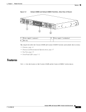
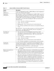
Chapter 1 Product Overview Features Figure 1-2 Catalyst 4948E and Catalyst 4948E-F Switches-Rear View of Chassis 330680 PWR - 540 AC 100 7 240 VAC - 3A 50 - 60 Hz INPUT OK OUTPUT OK 1 2 PWR - 540 AC 100... OK OUTPUT OK 3 1 Power supply 1 (primary) 2 Fan tray 3 Power supply 2 (redundant) This chapter describes the Catalyst 4948E and Catalyst 4948E-F switches and includes these sections: • Features, page 1-3 • Physical and Environmental Specifications, page 1-7 • Fan Tray, page 1-8 • Front Panel LEDs, page 1-11 Features Table 1-1 lists the features ...
Chapter 1 Product Overview Features Figure 1-2 Catalyst 4948E and Catalyst 4948E-F Switches-Rear View of Chassis 330680 PWR - 540 AC 100 7 240 VAC - 3A 50 - 60 Hz INPUT OK OUTPUT OK 1 2 PWR - 540 AC 100... OK OUTPUT OK 3 1 Power supply 1 (primary) 2 Fan tray 3 Power supply 2 (redundant) This chapter describes the Catalyst 4948E and Catalyst 4948E-F switches and includes these sections: • Features, page 1-3 • Physical and Environmental Specifications, page 1-7 • Fan Tray, page 1-8 • Front Panel LEDs, page 1-11 Features Table 1-1 lists the features ...
Installation Guide
Page 20
... B, "Transceiver, Chassis Connectors, and Cable and Adapter Specifications" for the console port. This port can be used to download software to the switch or transfer files to remote servers for switch management using standard console equipment. Each port has an RJ-45 connector. Catalyst 4948E and Catalyst 4948E-F Switch Installation Guide 1-4 OL-21561-02 A bicolor port...
... B, "Transceiver, Chassis Connectors, and Cable and Adapter Specifications" for the console port. This port can be used to download software to the switch or transfer files to remote servers for switch management using standard console equipment. Each port has an RJ-45 connector. Catalyst 4948E and Catalyst 4948E-F Switch Installation Guide 1-4 OL-21561-02 A bicolor port...
Installation Guide
Page 22
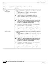
... A, "Power Supply Specifications" contains additional information on both of the power supplies for the Catalyst 4948E-F is color-coded blue. Note Appendix A, "Power Supply Specifications" contains additional information on both of the power supplies. Catalyst 4948E-F Note If the...C49E-300AC-R (300 W AC-input power supply). - Features Chapter 1 Product Overview Table 1-1 Catalyst 4948E and Catalyst 4948E-F Switch Features (continued) Feature Power supplies Catalyst 4948E Description • Supports one or two power supplies. Source AC can be covered using the...
... A, "Power Supply Specifications" contains additional information on both of the power supplies for the Catalyst 4948E-F is color-coded blue. Note Appendix A, "Power Supply Specifications" contains additional information on both of the power supplies. Catalyst 4948E-F Note If the...C49E-300AC-R (300 W AC-input power supply). - Features Chapter 1 Product Overview Table 1-1 Catalyst 4948E and Catalyst 4948E-F Switch Features (continued) Feature Power supplies Catalyst 4948E Description • Supports one or two power supplies. Source AC can be covered using the...
Installation Guide
Page 23
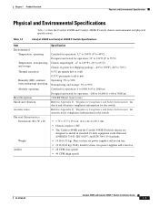
... kg). two power supplies and a fan tray. • 28 CFM (low speed) • 44 CFM (high speed) OL-21561-02 Catalyst 4948E and Catalyst 4948E-F Switch Installation Guide 1-7 Table 1-2 Catalyst 4948E and Catalyst 4948E-F Switch Specifications Item Environmental Temperature, operating Temperature, nonoperating and storage Thermal transition Humidity (RH), ambient (noncondensing) operating Altitude, operating Heat Dissipation Shock and...
... kg). two power supplies and a fan tray. • 28 CFM (low speed) • 44 CFM (high speed) OL-21561-02 Catalyst 4948E and Catalyst 4948E-F Switch Installation Guide 1-7 Table 1-2 Catalyst 4948E and Catalyst 4948E-F Switch Specifications Item Environmental Temperature, operating Temperature, nonoperating and storage Thermal transition Humidity (RH), ambient (noncondensing) operating Altitude, operating Heat Dissipation Shock and...
Installation Guide
Page 34
.... Caution Category 5e, Category 6, and Category 6a cables can occur between the field and the signals on the wires. Catalyst 4948E and Catalyst 4948E-F Switch Installation Guide 2-6 OL-21561-02 If you use twisted-pair cable in radio interference emanating from the plant wiring. •...a high-quality twisted-pair cable with one ground conductor for each data signal when applicable. The Federal Communications Commission (FCC) publishes specific regulations to limit the amount of grounding conductors, the plant wiring is unlikely to the module. The oil from a system can ...
.... Caution Category 5e, Category 6, and Category 6a cables can occur between the field and the signals on the wires. Catalyst 4948E and Catalyst 4948E-F Switch Installation Guide 2-6 OL-21561-02 If you use twisted-pair cable in radio interference emanating from the plant wiring. •...a high-quality twisted-pair cable with one ground conductor for each data signal when applicable. The Federal Communications Commission (FCC) publishes specific regulations to limit the amount of grounding conductors, the plant wiring is unlikely to the module. The oil from a system can ...
Installation Guide
Page 42
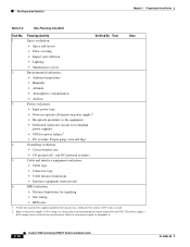
... for signaling • Site wiring • RFI levels 1. Verify that each power supply in Appendix A. 2-14 Catalyst 4948E and Catalyst 4948E-F Switch Installation Guide OL-21561-02 The power supply's kVA rating value is listed in the specifications table for Installation Table 2-2 Site Planning Checklist Task No. Planning Activity Verified By Time Date 1 Space...
... for signaling • Site wiring • RFI levels 1. Verify that each power supply in Appendix A. 2-14 Catalyst 4948E and Catalyst 4948E-F Switch Installation Guide OL-21561-02 The power supply's kVA rating value is listed in the specifications table for Installation Table 2-2 Site Planning Checklist Task No. Planning Activity Verified By Time Date 1 Space...
Installation Guide
Page 77
A A P P E N D I X Power Supply Specifications This appendix provides the specifications for the AC-input and DC-input power supplies supported on the Catalyst 4948E-F switch. OL-21561-02 Catalyst 4948E and Catalyst 4948E-F Switch Installation Guide A-1 This power supply is not supported on the Catalyst 4948E switch. Tip For additional information about the Cisco Catalyst 4948E and the Catalyst 4948E-F switches (including configuration examples and troubleshooting...
A A P P E N D I X Power Supply Specifications This appendix provides the specifications for the AC-input and DC-input power supplies supported on the Catalyst 4948E-F switch. OL-21561-02 Catalyst 4948E and Catalyst 4948E-F Switch Installation Guide A-1 This power supply is not supported on the Catalyst 4948E switch. Tip For additional information about the Cisco Catalyst 4948E and the Catalyst 4948E-F switches (including configuration examples and troubleshooting...
Installation Guide
Page 78
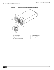
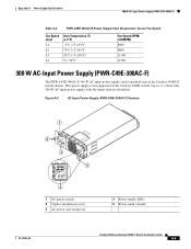
300 W AC-Input Power Supply (PWR-C49E-300AC-R) Appendix A Power Supply Specifications Figure A-1 AC-Input Power Supply (PWR-C49E-300AC-R) Features 1 2 3 PWR-C49E-300AC-R PWR-C49E-300AC-R 5 4 1 AC power switch 2 Captive installation screw 3 AC power cord receptacle 4 Power supply LEDs 5 Power supply handle 196260 Catalyst 4948E and Catalyst 4948E-F Switch Installation Guide A-2 OL-21561-02
300 W AC-Input Power Supply (PWR-C49E-300AC-R) Appendix A Power Supply Specifications Figure A-1 AC-Input Power Supply (PWR-C49E-300AC-R) Features 1 2 3 PWR-C49E-300AC-R PWR-C49E-300AC-R 5 4 1 AC power switch 2 Captive installation screw 3 AC power cord receptacle 4 Power supply LEDs 5 Power supply handle 196260 Catalyst 4948E and Catalyst 4948E-F Switch Installation Guide A-2 OL-21561-02
Installation Guide
Page 79
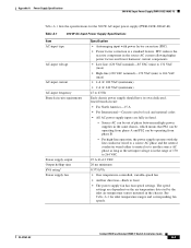
... the 300 W AC-input power supply (PWR-C49E-300AC-R). OL-21561-02 Catalyst 4948E and Catalyst 4948E-F Switch Installation Guide A-3 PFC reduces the reactive component in the chassis. Appendix A Power Supply Specifications 300 W AC-Input Power Supply (PWR-C49E-300AC-R) Table A-1 lists the specifications for inlet temperature ranges and corresponding fan speeds. Table A-1 300 W AC...
... the 300 W AC-input power supply (PWR-C49E-300AC-R). OL-21561-02 Catalyst 4948E and Catalyst 4948E-F Switch Installation Guide A-3 PFC reduces the reactive component in the chassis. Appendix A Power Supply Specifications 300 W AC-Input Power Supply (PWR-C49E-300AC-R) Table A-1 lists the specifications for inlet temperature ranges and corresponding fan speeds. Table A-1 300 W AC...
Installation Guide
Page 80
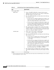
.../off switch turned on, or the power supply is lit red, rather than unlit, on , either of the following three situations occurs: - 300 W AC-Input Power Supply (PWR-C49E-300AC-R) Appendix A Power Supply Specifications Table A-1 300 W AC-Input Power Supply Specifications (continued) Item Specification Power...two situations occurs: - The OUTPUT OK LED is also lit red when a power supply fan failure is within limits. Catalyst 4948E and Catalyst 4948E-F Switch Installation Guide A-4 OL-21561-02 In chassis that are equipped with a single power supply, the INPUT OK LED is off...
.../off switch turned on, or the power supply is lit red, rather than unlit, on , either of the following three situations occurs: - 300 W AC-Input Power Supply (PWR-C49E-300AC-R) Appendix A Power Supply Specifications Table A-1 300 W AC-Input Power Supply Specifications (continued) Item Specification Power...two situations occurs: - The OUTPUT OK LED is also lit red when a power supply fan failure is within limits. Catalyst 4948E and Catalyst 4948E-F Switch Installation Guide A-4 OL-21561-02 In chassis that are equipped with a single power supply, the INPUT OK LED is off...
Installation Guide
Page 81
... Guide A-5 Figure A-2 shows the 300 W AC-input power supply with the major features identified. This power supply is not supported on the Catalyst 4948E switch. Appendix A Power Supply Specifications 300 W AC-Input Power Supply (PWR-C49E-300AC-F) Table A-2 PWR-C49E-300AC-R Power Supply Inlet Temperature Versus Fan Speed Fan Speed Level L1 L2... 11100 12700 300 W AC-Input Power Supply (PWR-C49E-300AC-F) The PWR-C49E-300AC-F 300 W AC-input power supply can be installed only in the Catalyst 4948E-F switch chassis.
... Guide A-5 Figure A-2 shows the 300 W AC-input power supply with the major features identified. This power supply is not supported on the Catalyst 4948E switch. Appendix A Power Supply Specifications 300 W AC-Input Power Supply (PWR-C49E-300AC-F) Table A-2 PWR-C49E-300AC-R Power Supply Inlet Temperature Versus Fan Speed Fan Speed Level L1 L2... 11100 12700 300 W AC-Input Power Supply (PWR-C49E-300AC-F) The PWR-C49E-300AC-F 300 W AC-input power supply can be installed only in the Catalyst 4948E-F switch chassis.
Installation Guide
Page 82
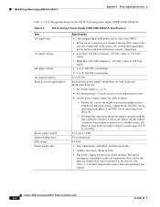
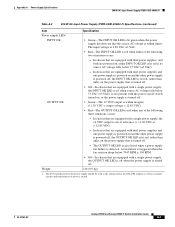
... the 300 W AC-input power supply (PWR-C49E-300AC-F). Source AC can be operating from phase B. - Catalyst 4948E and Catalyst 4948E-F Switch Installation Guide A-6 OL-21561-02 Table A-3 300 W AC-Input Power Supply (PWR-C49E-300AC-F) Specifications Item AC-input type AC-input voltage AC-input current AC-input frequency Branch circuit requirements Power...
... the 300 W AC-input power supply (PWR-C49E-300AC-F). Source AC can be operating from phase B. - Catalyst 4948E and Catalyst 4948E-F Switch Installation Guide A-6 OL-21561-02 Table A-3 300 W AC-Input Power Supply (PWR-C49E-300AC-F) Specifications Item AC-input type AC-input voltage AC-input current AC-input frequency Branch circuit requirements Power...
Installation Guide
Page 83
OUTPUT OK • Green-The 12 VDC output is within limits. OL-21561-02 Catalyst 4948E and Catalyst 4948E-F Switch Installation Guide A-7 In chassis that are equipped with dual power supplies and one power supply is powered on and the other power supply is ... OK LED is off when the power supply is turned off . - Appendix A Power Supply Specifications 300 W AC-Input Power Supply (PWR-C49E-300AC-F) Table A-3 300 W AC-Input Power Supply (PWR-C49E-300AC-F) Specifications (continued) Item Specification Power supply LEDs INPUT OK • Green-The INPUT OK LED is lit green when the...
OUTPUT OK • Green-The 12 VDC output is within limits. OL-21561-02 Catalyst 4948E and Catalyst 4948E-F Switch Installation Guide A-7 In chassis that are equipped with dual power supplies and one power supply is powered on and the other power supply is ... OK LED is off when the power supply is turned off . - Appendix A Power Supply Specifications 300 W AC-Input Power Supply (PWR-C49E-300AC-F) Table A-3 300 W AC-Input Power Supply (PWR-C49E-300AC-F) Specifications (continued) Item Specification Power supply LEDs INPUT OK • Green-The INPUT OK LED is lit green when the...

Installation Guide
Page 84
... Power Cord Reference Illustration Figure A-3 Figure A-4 Figure A-5 Figure A-6 Figure A-7 Figure A-8 Figure A-9 Figure A-10 Figure A-11 Catalyst 4948E and Catalyst 4948E-F Switch Installation Guide A-8 OL-21561-02 For Japan, ask your local electrical contractor to the AC-in receptacle on the power supply faceplate...7KACSW=) CAB-BS1363-C15-UK= BS 13632 (was CAB-7KACU=) 1. 300 W AC-Input Power Supply Power Cords Appendix A Power Supply Specifications Table A-4 PWR-C49E-300AC-F Power Supply Inlet Temperature Versus Fan Speed Fan Speed Level L1 L2 L3 L4 Inlet Temperature (T) (± ...
... Power Cord Reference Illustration Figure A-3 Figure A-4 Figure A-5 Figure A-6 Figure A-7 Figure A-8 Figure A-9 Figure A-10 Figure A-11 Catalyst 4948E and Catalyst 4948E-F Switch Installation Guide A-8 OL-21561-02 For Japan, ask your local electrical contractor to the AC-in receptacle on the power supply faceplate...7KACSW=) CAB-BS1363-C15-UK= BS 13632 (was CAB-7KACU=) 1. 300 W AC-Input Power Supply Power Cords Appendix A Power Supply Specifications Table A-4 PWR-C49E-300AC-F Power Supply Inlet Temperature Versus Fan Speed Fan Speed Level L1 L2 L3 L4 Inlet Temperature (T) (± ...

Installation Guide
Page 86
300 W AC-Input Power Supply Power Cords Appendix A Power Supply Specifications Figure A-6 CAB-C2316-C15-IT=, CAB-7KACI= (Italy) Plug: CEI 23-16/7 Cordset rating: 10 A, 250 V Length: 8 ft 2 in. (2.5 m) Connector: IEC 60320 C15 113349 192260 ...: NEMA 5-15P Figure A-8 CAB-N5K6A-NA (North America) Connector: IEC60320/C15 Plug: NEMA 6-15P Cordset rating: 10 A, 250 V Length: 8.2 ft Connector: IEC60320/C13 186570 A-10 Catalyst 4948E and Catalyst 4948E-F Switch Installation Guide OL-21561-02
300 W AC-Input Power Supply Power Cords Appendix A Power Supply Specifications Figure A-6 CAB-C2316-C15-IT=, CAB-7KACI= (Italy) Plug: CEI 23-16/7 Cordset rating: 10 A, 250 V Length: 8 ft 2 in. (2.5 m) Connector: IEC 60320 C15 113349 192260 ...: NEMA 5-15P Figure A-8 CAB-N5K6A-NA (North America) Connector: IEC60320/C15 Plug: NEMA 6-15P Cordset rating: 10 A, 250 V Length: 8.2 ft Connector: IEC60320/C13 186570 A-10 Catalyst 4948E and Catalyst 4948E-F Switch Installation Guide OL-21561-02