
Installation Guide
Page 6
... Modules and Alternative Wiring 4-1 X2 Modules 4-2 Module Maintenance Guidelines 4-5 Cleaning the Fiber-Optic Connectors 4-5 Additional Guidelines 4-7 Troubleshooting the Installation 5-1 Getting Started 5-2 Problem Solving to the System Component Level 5-2 Identifying Startup Problems 5-3 LED Readings 5-3 Troubleshooting the Power Supply 5-5 Contacting Customer Service 5-6 Specifications A-1 Console Port A-1 Catalyst 4900 Series Switch Installation Guide vi 78-18039-02
... Modules and Alternative Wiring 4-1 X2 Modules 4-2 Module Maintenance Guidelines 4-5 Cleaning the Fiber-Optic Connectors 4-5 Additional Guidelines 4-7 Troubleshooting the Installation 5-1 Getting Started 5-2 Problem Solving to the System Component Level 5-2 Identifying Startup Problems 5-3 LED Readings 5-3 Troubleshooting the Power Supply 5-5 Contacting Customer Service 5-6 Specifications A-1 Console Port A-1 Catalyst 4900 Series Switch Installation Guide vi 78-18039-02
Installation Guide
Page 29
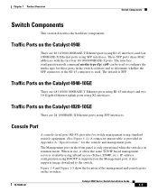
... ports using X2 interfaces. Traffic Ports on the Catalyst 4948-10GE There are 48 10/100/1000BASE-T Ethernet ports using RJ-45 interfaces and four 1000BASE-X Ethernet ports using standard console equipment. (See Figure 1-4.) A connector pinout table is provided in Appendix A, "Specifications,"... is supported on the switches. 78-18039-02 Catalyst 4900 Series Switch Installation Guide 1-7 When in use, it also supports image download to determine whether the SFP connector or the RJ-45 connector is in the switch software and to the switch. IP address configuration using...
... ports using X2 interfaces. Traffic Ports on the Catalyst 4948-10GE There are 48 10/100/1000BASE-T Ethernet ports using RJ-45 interfaces and four 1000BASE-X Ethernet ports using standard console equipment. (See Figure 1-4.) A connector pinout table is provided in Appendix A, "Specifications,"... is supported on the switches. 78-18039-02 Catalyst 4900 Series Switch Installation Guide 1-7 When in use, it also supports image download to determine whether the SFP connector or the RJ-45 connector is in the switch software and to the switch. IP address configuration using...
Installation Guide
Page 40
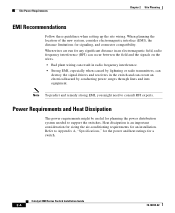
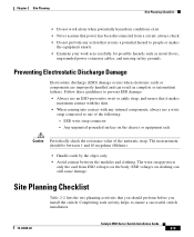
...EMI, you might be useful for planning the power distribution system needed to support the switches. Refer to consult RFI experts. When wires are run for signaling, and connector compatibility. Power Requirements and Heat Dissipation The power requirements might need to Appendix A, "... or radio transmitters, can destroy the signal drivers and receivers in the switch and can create an electrical hazard by conducting power surges through lines and into equipment. Catalyst 4900 Series Switch Installation Guide 2-4 78-18039-02 Site Power Requirements Chapter 2 Site Planning...
...EMI, you might be useful for planning the power distribution system needed to support the switches. Refer to consult RFI experts. When wires are run for signaling, and connector compatibility. Power Requirements and Heat Dissipation The power requirements might need to Appendix A, "... or radio transmitters, can destroy the signal drivers and receivers in the switch and can create an electrical hazard by conducting power surges through lines and into equipment. Catalyst 4900 Series Switch Installation Guide 2-4 78-18039-02 Site Power Requirements Chapter 2 Site Planning...
Installation Guide
Page 42
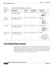
... on all AC or DC installations, using M4x 8mm bolts and then to the chassis using only approved copper connectors. Attach the provided two hole ground lug to the central office (CO) or other interior ground system with number 6 AWG wire. Grounding Requirements Chapter 2 Site ... VAC, 10 A BS 546 203795 Grounding Requirements Grounding is recommended on the right side of the chassis, and either one may be used. (See Figure 2-1.) Catalyst 4900 Series Switch Installation Guide 2-6 78-18039-02
... on all AC or DC installations, using M4x 8mm bolts and then to the chassis using only approved copper connectors. Attach the provided two hole ground lug to the central office (CO) or other interior ground system with number 6 AWG wire. Grounding Requirements Chapter 2 Site ... VAC, 10 A BS 546 203795 Grounding Requirements Grounding is recommended on the right side of the chassis, and either one may be used. (See Figure 2-1.) Catalyst 4900 Series Switch Installation Guide 2-6 78-18039-02
Installation Guide
Page 45
...wrist or ankle strap, and ensure that creates a potential hazard to ensure a successful switch installation. 78-18039-02 Catalyst 4900 Series Switch Installation Guide 2-9 The wrist strap protects only the card from a circuit; always ...check. • Do not perform any action that it makes maximum contact with the skin. • When coming into contact with any internal components, always use a wrist strap connected to one of the antistatic strap. ESD wrist strap connector...
...wrist or ankle strap, and ensure that creates a potential hazard to ensure a successful switch installation. 78-18039-02 Catalyst 4900 Series Switch Installation Guide 2-9 The wrist strap protects only the card from a circuit; always ...check. • Do not perform any action that it makes maximum contact with the skin. • When coming into contact with any internal components, always use a wrist strap connected to one of the antistatic strap. ESD wrist strap connector...
Installation Guide
Page 46
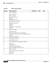
... the equipment Dedicated (separate) circuits for redundant power supplies UPS for power failures 4 Grounding evaluation: Circuit breaker size 5 Cable and interface equipment evaluation: Cable type Connector type Cable distance limitations Interface equipment (transceivers) 6 EMI evaluation: Distance limitations for signaling Site wiring RFI levels 2-10 Catalyst 4900 Series Switch Installation Guide 78-18039-02
... the equipment Dedicated (separate) circuits for redundant power supplies UPS for power failures 4 Grounding evaluation: Circuit breaker size 5 Cable and interface equipment evaluation: Cable type Connector type Cable distance limitations Interface equipment (transceivers) 6 EMI evaluation: Distance limitations for signaling Site wiring RFI levels 2-10 Catalyst 4900 Series Switch Installation Guide 78-18039-02
Installation Guide
Page 48
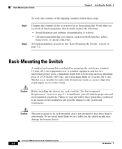
... cables, transceivers, or special connectors To begin installation, proceed to the switch. Failure to read the "Site Environmental Requirements" section on page 3-2. This kit is not intended to the system and components. Catalyst 4900 Series Switch Installation Guide 3-2 78-18039-...02 Verify that you received all listed equipment, which should include the following: • Switch hardware and software documentation, if ordered • Optional equipment...
... cables, transceivers, or special connectors To begin installation, proceed to the switch. Failure to read the "Site Environmental Requirements" section on page 3-2. This kit is not intended to the system and components. Catalyst 4900 Series Switch Installation Guide 3-2 78-18039-...02 Verify that you received all listed equipment, which should include the following: • Switch hardware and software documentation, if ordered • Optional equipment...
Installation Guide
Page 61
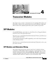
... documents at the following location: http://www.cisco.com/en/US/products/hw/modules/ps5455/products_device_sup port_tables_list.html SFP Modules and Alternative Wiring The Catalyst 4948 switches have four ports that can be configured with any combination of SFP modules with LC connectors, as shown in the switch software and determines whether the SFP or the...
... documents at the following location: http://www.cisco.com/en/US/products/hw/modules/ps5455/products_device_sup port_tables_list.html SFP Modules and Alternative Wiring The Catalyst 4948 switches have four ports that can be configured with any combination of SFP modules with LC connectors, as shown in the switch software and determines whether the SFP or the...
Installation Guide
Page 62
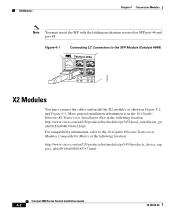
...Transceiver Installation Note at the following location: http://www.cisco.com/en/US/products/hw/modules/ps5455/prod_installation_gu ide09186a00803469ed.html For compatibility information, refer to the SFP Module (Catalyst 4948) Catalyst 4948 113146 CON AUX 45 46 47 48 X2 Modules ...port 48. Figure 4-1 Connecting LC Connectors to the 10-Gigabit Ethernet Transceiver Modules Compatibility Matrix at the following location: http://www.cisco.com/en/US/products/hw/modules/ps5455/products_device_sup port_table09186a00803857e7.html Catalyst 4900 Series Switch Installation Guide 4-2 78-18039-02...
...Transceiver Installation Note at the following location: http://www.cisco.com/en/US/products/hw/modules/ps5455/prod_installation_gu ide09186a00803469ed.html For compatibility information, refer to the SFP Module (Catalyst 4948) Catalyst 4948 113146 CON AUX 45 46 47 48 X2 Modules ...port 48. Figure 4-1 Connecting LC Connectors to the 10-Gigabit Ethernet Transceiver Modules Compatibility Matrix at the following location: http://www.cisco.com/en/US/products/hw/modules/ps5455/products_device_sup port_table09186a00803857e7.html Catalyst 4900 Series Switch Installation Guide 4-2 78-18039-02...

Installation Guide
Page 63
See the Catalyst 4500 Series Module Installation Guide for operation on an SMF cable is directly coupled to an MMF cable, an effect known as Differential Mode Delay (DMD) might occur. Chapter 4 Transceiver Modules X2 Modules Figure 4-2 Connecting SC Connectors to the X2 Module Catalyst WS-C4948 10GE X2-1 X2-2 CON MGT 130088 If a module designed for more information. 78-18039-02 Catalyst 4900 Series Switch Installation Guide 4-3
See the Catalyst 4500 Series Module Installation Guide for operation on an SMF cable is directly coupled to an MMF cable, an effect known as Differential Mode Delay (DMD) might occur. Chapter 4 Transceiver Modules X2 Modules Figure 4-2 Connecting SC Connectors to the X2 Module Catalyst WS-C4948 10GE X2-1 X2-2 CON MGT 130088 If a module designed for more information. 78-18039-02 Catalyst 4900 Series Switch Installation Guide 4-3
Installation Guide
Page 64
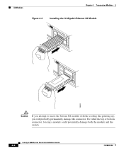
For either the top or bottom connector, forcing a module could potentially damage both the module and the switch. Catalyst 4900 Series Switch Installation Guide 4-4 78-18039-02 X2 Modules Chapter 4 Transceiver Modules Figure 4-3 Installing the 10-Gigabit Ethernet X2 Module Catalyst WS-C4948 10GE CON X1 MGT LINK X2 Catalyst WS-C4948 10GE CON X1 MGT X2 130091 Caution If you attempt to insert the bottom X2 module with the cooling fins pointing up, you will probably permanently damage the connector.
For either the top or bottom connector, forcing a module could potentially damage both the module and the switch. Catalyst 4900 Series Switch Installation Guide 4-4 78-18039-02 X2 Modules Chapter 4 Transceiver Modules Figure 4-3 Installing the 10-Gigabit Ethernet X2 Module Catalyst WS-C4948 10GE CON X1 MGT LINK X2 Catalyst WS-C4948 10GE CON X1 MGT X2 130091 Caution If you attempt to insert the bottom X2 module with the cooling fins pointing up, you will probably permanently damage the connector.
Installation Guide
Page 65
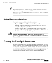
...trapped foreign material. 78-18039-02 Catalyst 4900 Series Switch Installation Guide 4-5 Warning Invisible laser radiation may be absolutely free of the optical connector. Because dust particles range from disconnected fibers or connectors. Statement 1051 Cleaning the Fiber-Optic Connectors In a fiber-optic system, .... • The most common source of the optical connectors. Use an alcohol swab or Kim-Wipe to several microns in diameter, dust and any contamination at this URL: http://www.cisco.com/en/US/tech/tk482/tk876/technologies_white_paper09186a 0080254eba.shtml Module...
...trapped foreign material. 78-18039-02 Catalyst 4900 Series Switch Installation Guide 4-5 Warning Invisible laser radiation may be absolutely free of the optical connector. Because dust particles range from disconnected fibers or connectors. Statement 1051 Cleaning the Fiber-Optic Connectors In a fiber-optic system, .... • The most common source of the optical connectors. Use an alcohol swab or Kim-Wipe to several microns in diameter, dust and any contamination at this URL: http://www.cisco.com/en/US/tech/tk482/tk876/technologies_white_paper09186a 0080254eba.shtml Module...
Installation Guide
Page 66
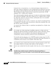
... insertion loss, is a critical performance characteristic of the fiber. Keep the connectors clean at all times, and keep the dust covers installed when the connectors are a common source of connector and the proper cleaning and connection techniques. Statement 1051 Catalyst 4900 Series Switch Installation Guide 4-6 78-18039-02 Return loss specifies the amount of light...
... insertion loss, is a critical performance characteristic of the fiber. Keep the connectors clean at all times, and keep the dust covers installed when the connectors are a common source of connector and the proper cleaning and connection techniques. Statement 1051 Catalyst 4900 Series Switch Installation Guide 4-6 78-18039-02 Return loss specifies the amount of light...
Installation Guide
Page 67
... side, follows the previous directions, and follows these guidelines: • Clean the connectors using the connectors or while you are cleaning the chassis. 78-18039-02 Catalyst 4900 Series Switch Installation Guide 4-7 Do not look directly into the aperture. Additional Guidelines The connectors used inside the system have been cleaned by the manufacturer and connected...
... side, follows the previous directions, and follows these guidelines: • Clean the connectors using the connectors or while you are cleaning the chassis. 78-18039-02 Catalyst 4900 Series Switch Installation Guide 4-7 Do not look directly into the aperture. Additional Guidelines The connectors used inside the system have been cleaned by the manufacturer and connected...

Installation Guide
Page 68
Cleaning the Fiber-Optic Connectors Chapter 4 Transceiver Modules Catalyst 4900 Series Switch Installation Guide 4-8 78-18039-02
Cleaning the Fiber-Optic Connectors Chapter 4 Transceiver Modules Catalyst 4900 Series Switch Installation Guide 4-8 78-18039-02
Installation Guide
Page 80
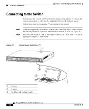
..., insert the RJ-45 connector into the console port that is located on the front of the adapter cable to a PC serial port, or attach an appropriate adapter to the terminal. Figure B-1 Connecting a Switch to a PC 1 PS1 PS2 FAN STATUS 1 16 17 32 33 Catalyst 4948 CON 48 MGT 45 46... 47 48 3 2 181874 1 Switch 2 Laptop 3 RJ-45-to perform the initial configuration. To connect the switch console port to a PC, use the console port to -...
..., insert the RJ-45 connector into the console port that is located on the front of the adapter cable to a PC serial port, or attach an appropriate adapter to the terminal. Figure B-1 Connecting a Switch to a PC 1 PS1 PS2 FAN STATUS 1 16 17 32 33 Catalyst 4948 CON 48 MGT 45 46... 47 48 3 2 181874 1 Switch 2 Laptop 3 RJ-45-to perform the initial configuration. To connect the switch console port to a PC, use the console port to -...
Installation Guide
Page 81
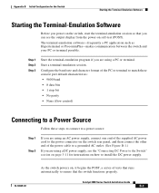
Start a terminal-emulation session. Catalyst 4900 Series Switch Installation Guide B-3 Appendix B Initial Configuration for instructions on how to install the DC power supply. 78-18039-02 As the switch powers on, it begins the POST, a series of tests that runs automatically to a grounded AC outlet. (See Figure B-1.) If ...you are using a DC power supply, see the output display from the power-on the switch rear panel, and then connect the other end of the supplied AC power cord to the power connector on self-test (POST). Step 1 Step 2 Step 3 Start the terminal-emulation program if...
Start a terminal-emulation session. Catalyst 4900 Series Switch Installation Guide B-3 Appendix B Initial Configuration for instructions on how to install the DC power supply. 78-18039-02 As the switch powers on, it begins the POST, a series of tests that runs automatically to a grounded AC outlet. (See Figure B-1.) If ...you are using a DC power supply, see the output display from the power-on the switch rear panel, and then connect the other end of the supplied AC power cord to the power connector on self-test (POST). Step 1 Step 2 Step 3 Start the terminal-emulation program if...
Installation Guide
Page 119
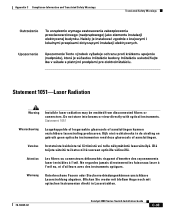
Kijk niet rechtstreeks in Laserstrahlen. 78-18039-02 Catalyst 4900 Series Switch Installation Guide C-33 Attention Les fibres ou connecteurs débranchés risquent d'émettre des rayonnements laser invisibles à l'œil. Ne... Compliance Information and Translated Safety Warnings Translated Safety Warnings Statement 1051-Laser Radiation Warning Invisible laser radiation may be emitted from disconnected fibers or connectors. Do not stare into beams or view directly with optical instruments. Blicken Sie weder mit bloßem Auge noch mit optischen Instrumenten direkt...
Kijk niet rechtstreeks in Laserstrahlen. 78-18039-02 Catalyst 4900 Series Switch Installation Guide C-33 Attention Les fibres ou connecteurs débranchés risquent d'émettre des rayonnements laser invisibles à l'œil. Ne... Compliance Information and Translated Safety Warnings Translated Safety Warnings Statement 1051-Laser Radiation Warning Invisible laser radiation may be emitted from disconnected fibers or connectors. Do not stare into beams or view directly with optical instruments. Blicken Sie weder mit bloßem Auge noch mit optischen Instrumenten direkt...
Installation Guide
Page 140
... 2-1 F fan tray cooling 1-11 failure 1-12 status LED 1-11 fiber-optic connectors 4-7 G grounding requirement, DC systems 2-6 H hardware description power supply 1-12 heat dissipation determining 2-4 I installation connecting to a power source B-3 IN-2 Catalyst 4900 Series Switch Installation Guide starting the terminal-emulation software B-3 installing the switch guidelines 3-2 lifting 3-5 procedure 3-6 safety overview 2-7 tools required 3-5 troubleshooting 5-1 L label, chassis...
... 2-1 F fan tray cooling 1-11 failure 1-12 status LED 1-11 fiber-optic connectors 4-7 G grounding requirement, DC systems 2-6 H hardware description power supply 1-12 heat dissipation determining 2-4 I installation connecting to a power source B-3 IN-2 Catalyst 4900 Series Switch Installation Guide starting the terminal-emulation software B-3 installing the switch guidelines 3-2 lifting 3-5 procedure 3-6 safety overview 2-7 tools required 3-5 troubleshooting 5-1 L label, chassis...