
Hardware Installation Guide
Page 6
... Power Connectors 1-21 Internal Power Supply Connector 1-21 DC Power Connector 1-21 Cisco RPS Connector 1-22 Console Port 1-23 2 C H A P T E R Installation 2-1 Preparing for Installation 2-1 Warnings 2-1 EMC Regulatory Statements 2-4 U.S.A. 2-4 Taiwan 2-4 Japan 2-5 Korea 2-5 Hungary 2-6 Installation Guidelines 2-6 Verifying Package Contents 2-7 Installing the Switch on a Table or Shelf 2-9 Installing the Switch in a Rack 2-9 Removing Screws from the Switch 2-11 Attaching the Brackets to a Catalyst...
... Power Connectors 1-21 Internal Power Supply Connector 1-21 DC Power Connector 1-21 Cisco RPS Connector 1-22 Console Port 1-23 2 C H A P T E R Installation 2-1 Preparing for Installation 2-1 Warnings 2-1 EMC Regulatory Statements 2-4 U.S.A. 2-4 Taiwan 2-4 Japan 2-5 Korea 2-5 Hungary 2-6 Installation Guidelines 2-6 Verifying Package Contents 2-7 Installing the Switch on a Table or Shelf 2-9 Installing the Switch in a Rack 2-9 Removing Screws from the Switch 2-11 Attaching the Brackets to a Catalyst...

Hardware Installation Guide
Page 8
... Identifying a Rollover Cable B-6 Connecting to a PC B-6 Connecting to a Terminal B-7 Translated Safety Warnings C-1 Attaching the Cisco RPS (model PWR600-AC-RPS) C-1 Attaching the Cisco RPS (model PWR300-AC-RPS-N1) C-2 Qualified Personnel Warning C-3 Installation Warning C-4 Jewelry Removal Warning C-5 Stacking the... C-9 TN Power Warning C-10 Ground Connection Warning C-11 Circuit Breaker (15A) Warning C-12 Grounded Equipment Warning C-14 Supply Circuit Warning C-15 Voltage Warning C-16 Power Supply Warning C-17 Lightning Activity Warning C-19 Product Disposal Warning C-21 Catalyst 2900 Series ...
... Identifying a Rollover Cable B-6 Connecting to a PC B-6 Connecting to a Terminal B-7 Translated Safety Warnings C-1 Attaching the Cisco RPS (model PWR600-AC-RPS) C-1 Attaching the Cisco RPS (model PWR300-AC-RPS-N1) C-2 Qualified Personnel Warning C-3 Installation Warning C-4 Jewelry Removal Warning C-5 Stacking the... C-9 TN Power Warning C-10 Ground Connection Warning C-11 Circuit Breaker (15A) Warning C-12 Grounded Equipment Warning C-14 Supply Circuit Warning C-15 Voltage Warning C-16 Power Supply Warning C-17 Lightning Activity Warning C-19 Product Disposal Warning C-21 Catalyst 2900 Series ...

Hardware Installation Guide
Page 33
... other Catalyst 2900 XL and Catalyst 3500 XL switches use the Cisco RPS 300 (model PWR300-AC-RPS-N1). If the switch power supply fails, the switch powers down and after 15 seconds restarts, using power from the RPS. RPS is connected but not functioning. • The RPS could have failed. The RPS and the switch AC power supply are both powered up power, if...
... other Catalyst 2900 XL and Catalyst 3500 XL switches use the Cisco RPS 300 (model PWR300-AC-RPS-N1). If the switch power supply fails, the switch powers down and after 15 seconds restarts, using power from the RPS. RPS is connected but not functioning. • The RPS could have failed. The RPS and the switch AC power supply are both powered up power, if...

Hardware Installation Guide
Page 34
...does not, the RPS fan could have a port LED. Contact Cisco Systems. The internal power supply in a switch has failed, and the RPS is the default mode. These port LEDs, as a group or individually, display information about the switch and about the individual ports. Table 1-6 and Table 1-7 list ...: auto • Gigabit ports: auto The port operating speed: 10 or 100 Mbps. 1-14 Catalyst 2900 Series XL Hardware Installation Guide 78-6461-04 This is providing power to the switch (redundancy has been allocated to this device). Front-Panel Description Chapter 1 Product Overview Table 1-3 RPS...
...does not, the RPS fan could have a port LED. Contact Cisco Systems. The internal power supply in a switch has failed, and the RPS is the default mode. These port LEDs, as a group or individually, display information about the switch and about the individual ports. Table 1-6 and Table 1-7 list ...: auto • Gigabit ports: auto The port operating speed: 10 or 100 Mbps. 1-14 Catalyst 2900 Series XL Hardware Installation Guide 78-6461-04 This is providing power to the switch (redundancy has been allocated to this device). Front-Panel Description Chapter 1 Product Overview Table 1-3 RPS...
Hardware Installation Guide
Page 41
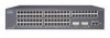
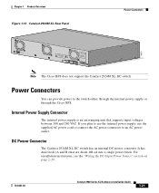
... plan to use the internal power supply, use the supplied AC power cord to connect the AC power connector to the switch either through the internal power supply or through the Cisco RPS. DC Power Connector The Catalyst 2924M XL DC switch has an internal DC-power converter. Note The Cisco RPS does not support the Catalyst 2924M XL DC switch. Chapter 1 Product Overview Figure 1-13...
... plan to use the internal power supply, use the supplied AC power cord to connect the AC power connector to the switch either through the internal power supply or through the Cisco RPS. DC Power Connector The Catalyst 2924M XL DC switch has an internal DC-power converter. Note The Cisco RPS does not support the Catalyst 2924M XL DC switch. Chapter 1 Product Overview Figure 1-13...

Hardware Installation Guide
Page 43
...device internal power supply has been brought up or replaced, the RPS automatically stops powering the device. If more information on page 2-42. 78-6461-04 Catalyst 2900 Series XL Hardware Installation Guide 1-23 Console Port You can connect a switch to a PC through the switch console port ... connect the switch console port to the Cisco Redundant Power System 300 Hardware Installation Guide. For more than one switch fails at the same time, any subsequent switch is not supported by using the supplied rollover cable and DB-9 adapter. It automatically senses when the power supply of a...
...device internal power supply has been brought up or replaced, the RPS automatically stops powering the device. If more information on page 2-42. 78-6461-04 Catalyst 2900 Series XL Hardware Installation Guide 1-23 Console Port You can connect a switch to a PC through the switch console port ... connect the switch console port to the Cisco Redundant Power System 300 Hardware Installation Guide. For more than one switch fails at the same time, any subsequent switch is not supported by using the supplied rollover cable and DB-9 adapter. It automatically senses when the power supply of a...
Hardware Installation Guide
Page 47
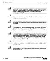
...power switch, line voltages are present within the power supply when the power cord is used on the label is connected. Ensure that receptacle. If the voltage indicated on the phase conductors (all national laws and regulations. 78-6461-04 Catalyst 2900 Series XL Hardware Installation Guide 2-3 Warning Do not touch the power supply when the power... equipment is not overloaded. For systems with a power switch, line voltages are present within the power supply even when the power switch is off and the power cord is connected to all current-carrying conductors). Ensure...
...power switch, line voltages are present within the power supply when the power cord is used on the label is connected. Ensure that receptacle. If the voltage indicated on the phase conductors (all national laws and regulations. 78-6461-04 Catalyst 2900 Series XL Hardware Installation Guide 2-3 Warning Do not touch the power supply when the power... equipment is not overloaded. For systems with a power switch, line voltages are present within the power supply even when the power switch is off and the power cord is connected to all current-carrying conductors). Ensure...
Hardware Installation Guide
Page 159
... (telco rack-mount) modules 1-8 mounting brackets 2-9 attaching 2-11, 2-15, 2-22 N no on/off switch warning C-24 O overtemperature warning C-9 P PC, connecting to switch 2-42 performance problems, solving 3-3 personnel warning C-3 pinouts 10/100BASE-T ports B-2 cable, straight-through and crossover...16 to 1-18 POST results 2-24 power connecting to 2-24 warning C-15 power connectors 1-21 power on 2-24 power supply AC power outlet 1-21 RPS connector 1-21 warning C-17 product disposal warning C-21 Q qualified personnel warning C-3 78-6461-04 Catalyst 2900 Series XL Hardware Installation Guide ...
... (telco rack-mount) modules 1-8 mounting brackets 2-9 attaching 2-11, 2-15, 2-22 N no on/off switch warning C-24 O overtemperature warning C-9 P PC, connecting to switch 2-42 performance problems, solving 3-3 personnel warning C-3 pinouts 10/100BASE-T ports B-2 cable, straight-through and crossover...16 to 1-18 POST results 2-24 power connecting to 2-24 warning C-15 power connectors 1-21 power on 2-24 power supply AC power outlet 1-21 RPS connector 1-21 warning C-17 product disposal warning C-21 Q qualified personnel warning C-3 78-6461-04 Catalyst 2900 Series XL Hardware Installation Guide ...
Software Guide
Page 17
... Reports for Tech Support 27-12 Power Management 28-1 Understanding How Power Management Works on the Catalyst 4500 Series Switches 28-1 Power Management Overview 28-2 Understanding Power Management Modes 28-2 Available Power for Power Supplies 28-4 Power Management Limitations 28-4 1400 W DC Power Supply Guidelines and Restrictions 28-5 Understanding How Power Management Works on the Catalyst 4006 Switch 28-6 Understanding Power Redundancy 28-6 1+1 Redundancy Mode Guidelines...
... Reports for Tech Support 27-12 Power Management 28-1 Understanding How Power Management Works on the Catalyst 4500 Series Switches 28-1 Power Management Overview 28-2 Understanding Power Management Modes 28-2 Available Power for Power Supplies 28-4 Power Management Limitations 28-4 1400 W DC Power Supply Guidelines and Restrictions 28-5 Understanding How Power Management Works on the Catalyst 4006 Switch 28-6 Understanding Power Redundancy 28-6 1+1 Redundancy Mode Guidelines...
Software Guide
Page 31
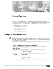
... 3-slot chassis • Optional redundant power supplies Catalyst 4006 • Modular 6-slot chassis • 30-Gbps backplane • Two power supplies with optional third power supply 78-15486-01 Catalyst 4500 Series, Catalyst 2948G, Catalyst 2980G Switches Software Configuration Guide-Release 8.1 1-1 These switches provide switched connections to the Catalyst 4000 Series Installation Guide, Catalyst 4500 Series Switch Installation Guide, and the Catalyst 4912G Installation Guide. Product Overview CH...
... 3-slot chassis • Optional redundant power supplies Catalyst 4006 • Modular 6-slot chassis • 30-Gbps backplane • Two power supplies with optional third power supply 78-15486-01 Catalyst 4500 Series, Catalyst 2948G, Catalyst 2980G Switches Software Configuration Guide-Release 8.1 1-1 These switches provide switched connections to the Catalyst 4000 Series Installation Guide, Catalyst 4500 Series Switch Installation Guide, and the Catalyst 4912G Installation Guide. Product Overview CH...
Software Guide
Page 32
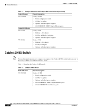
... Fast Ethernet ports Catalyst 4500 Series, Catalyst 2948G, Catalyst 2980G Switches Software Configuration Guide-Release 8.1 1-2 78-15486-01 Catalyst 2948G Switch Chapter 1 Product Overview Table 1-1 Catalyst 4000 Series and Catalyst 4500 Series Switches (continued) Product Number WS-C4912G Catalyst 4500 Series WS-C4503 WS-C4506 Chassis Description Catalyst 4912G • Fixed-configuration switch • 12-Gbps backplane • Optional redundant power supplies • 12 1000BASE...
... Fast Ethernet ports Catalyst 4500 Series, Catalyst 2948G, Catalyst 2980G Switches Software Configuration Guide-Release 8.1 1-2 78-15486-01 Catalyst 2948G Switch Chapter 1 Product Overview Table 1-1 Catalyst 4000 Series and Catalyst 4500 Series Switches (continued) Product Number WS-C4912G Catalyst 4500 Series WS-C4503 WS-C4506 Chassis Description Catalyst 4912G • Fixed-configuration switch • 12-Gbps backplane • Optional redundant power supplies • 12 1000BASE...

Software Guide
Page 33
... redundant power supplies • Two 1000BASE-X (GBIC) Gigabit Ethernet ports • 80 10/100BASE-TX Fast Ethernet ports Supervisor Engine Software The supervisor engine software is factory installed on the module. For descriptions of the Catalyst 2980G switch hardware, refer to the Catalyst 4500 Series, Catalyst 2948G, and Catalyst 2980G Switches Command Reference. 78-15486-01 Catalyst 4500 Series, Catalyst 2948G, Catalyst 2980G Switches Software...
... redundant power supplies • Two 1000BASE-X (GBIC) Gigabit Ethernet ports • 80 10/100BASE-TX Fast Ethernet ports Supervisor Engine Software The supervisor engine software is factory installed on the module. For descriptions of the Catalyst 2980G switch hardware, refer to the Catalyst 4500 Series, Catalyst 2948G, and Catalyst 2980G Switches Command Reference. 78-15486-01 Catalyst 4500 Series, Catalyst 2948G, Catalyst 2980G Switches Software...
Software Guide
Page 373
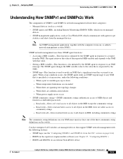
When temperature limitations are spanning tree topology changes - When power supply errors occur • SNMP community strings-SNMP community strings authenticate access to community strings - does not allow access to MIB objects...supervisor engine module software (see Chapter 25, "Configuring RMON") • RMON and RMON2 on an external SwitchProbe device 78-15486-01 Catalyst 4500 Series, Catalyst 2948G, Catalyst 2980G Switches Software Configuration Guide-Release 8.1 24-5 When there are exceeded - When there are managed devices that support SNMP network management with the following...
When temperature limitations are spanning tree topology changes - When power supply errors occur • SNMP community strings-SNMP community strings authenticate access to community strings - does not allow access to MIB objects...supervisor engine module software (see Chapter 25, "Configuring RMON") • RMON and RMON2 on an external SwitchProbe device 78-15486-01 Catalyst 4500 Series, Catalyst 2948G, Catalyst 2980G Switches Software Configuration Guide-Release 8.1 24-5 When there are exceeded - When there are managed devices that support SNMP network management with the following...

Software Guide
Page 412
...Catalyst 2948G, Catalyst 2980G Switches Software Configuration Guide-Release 8.1 78-15486-01 Command set the system clock, perform this task in to the switch. Configuring a Login Banner To configure a login banner, perform this task in to the switch. Setting the System Clock Chapter 27 Administering the Switch disable 9600 0% 0% Wed Apr 24 2002, 15:46:01 Power... Capacity of the Chassis:2 supplies WARNING:Power supplies of different...
...Catalyst 2948G, Catalyst 2980G Switches Software Configuration Guide-Release 8.1 78-15486-01 Command set the system clock, perform this task in to the switch. Configuring a Login Banner To configure a login banner, perform this task in to the switch. Setting the System Clock Chapter 27 Administering the Switch disable 9600 0% 0% Wed Apr 24 2002, 15:46:01 Power... Capacity of the Chassis:2 supplies WARNING:Power supplies of different...

Software Guide
Page 422
... enough power to support the power requirements of the Catalyst 4500 series switching modules. 28-2 Catalyst 4500 Series, Catalyst 2948G, Catalyst 2980G Switches Software Configuration Guide-Release 8.1 78-15486-01 Combined mode requires that is provided by the power supplies in either combined or redundant mode for the power requirements of the switch configuration. If the primary power supply fails, the second power supply supports the switch without...
... enough power to support the power requirements of the Catalyst 4500 series switching modules. 28-2 Catalyst 4500 Series, Catalyst 2948G, Catalyst 2980G Switches Software Configuration Guide-Release 8.1 78-15486-01 Combined mode requires that is provided by the power supplies in either combined or redundant mode for the power requirements of the switch configuration. If the primary power supply fails, the second power supply supports the switch without...

Software Guide
Page 423
... power supply in power supply bay 1 (PS1) and ignores the power supply in a Catalyst 4500 series switch are less than the maximum available power for the chassis and inline power for the power supply. Chapter 28 Power Management Understanding How Power Management Works on page 28-4 for a list of the maximum available power for chassis and inline power for each power supply. 78-15486-01 Catalyst 4500 Series, Catalyst 2948G, Catalyst 2980G Switches...
... power supply in power supply bay 1 (PS1) and ignores the power supply in a Catalyst 4500 series switch are less than the maximum available power for the chassis and inline power for the power supply. Chapter 28 Power Management Understanding How Power Management Works on page 28-4 for a list of the maximum available power for chassis and inline power for each power supply. 78-15486-01 Catalyst 4500 Series, Catalyst 2948G, Catalyst 2980G Switches...

Software Guide
Page 424
... configuration. 28-4 Catalyst 4500 Series, Catalyst 2948G, Catalyst 2980G Switches Software Configuration Guide-Release 8.1 78-15486-01 Note To compute the power requirements and verify that your system has enough power, add the power that is consumed by the power supplies. • If you insert a single power supply into the switch and then set combined mode, the switch displays this message: Insufficient power supplies present for...
... configuration. 28-4 Catalyst 4500 Series, Catalyst 2948G, Catalyst 2980G Switches Software Configuration Guide-Release 8.1 78-15486-01 Note To compute the power requirements and verify that your system has enough power, add the power that is consumed by the power supplies. • If you insert a single power supply into the switch and then set combined mode, the switch displays this message: Insufficient power supplies present for...

Software Guide
Page 425
...: Module has been inserted and Insufficient power supplies operating. • If you power down . Refer to the power supply documentation that shipped with a variety of the inline power switch can be reported to software. The inline power is working properly. 78-15486-01 Catalyst 4500 Series, Catalyst 2948G, Catalyst 2980G Switches Software Configuration Guide-Release 8.1 28-5 If the power supply fan fails, the display shows...
...: Module has been inserted and Insufficient power supplies operating. • If you power down . Refer to the power supply documentation that shipped with a variety of the inline power switch can be reported to software. The inline power is working properly. 78-15486-01 Catalyst 4500 Series, Catalyst 2948G, Catalyst 2980G Switches Software Configuration Guide-Release 8.1 28-5 If the power supply fan fails, the display shows...

Software Guide
Page 426
... page 28-1. Understanding Power Redundancy The Catalyst 4006 switch contains holding bays for the Catalyst 4000 series switches support a limited module configuration on a reduced number of available power. 28-6 Catalyst 4500 Series, Catalyst 2948G, Catalyst 2980G Switches Software Configuration Guide-Release 8.1 78-15486-01 You can provide. some switch configurations require more power than the power that is supplied by setting the power redundancy to operate...
... page 28-1. Understanding Power Redundancy The Catalyst 4006 switch contains holding bays for the Catalyst 4000 series switches support a limited module configuration on a reduced number of available power. 28-6 Catalyst 4500 Series, Catalyst 2948G, Catalyst 2980G Switches Software Configuration Guide-Release 8.1 78-15486-01 You can provide. some switch configurations require more power than the power that is supplied by setting the power redundancy to operate...

Software Guide
Page 427
... that is available to the system is the power of a single power supply. To determine the power consumption for the specified configuration. Chapter 28 Power Management Understanding How Power Management Works on the Catalyst 4006 Switch If you choose to use a 1+1 redundancy configuration...a third power supply in your system has enough power, add up the power that are installed in the chassis than the single power supply provides, the switch places the newly inserted module into reset mode. 78-15486-01 Catalyst 4500 Series, Catalyst 2948G, Catalyst 2980G Switches Software Configuration...
... that is available to the system is the power of a single power supply. To determine the power consumption for the specified configuration. Chapter 28 Power Management Understanding How Power Management Works on the Catalyst 4006 Switch If you choose to use a 1+1 redundancy configuration...a third power supply in your system has enough power, add up the power that are installed in the chassis than the single power supply provides, the switch places the newly inserted module into reset mode. 78-15486-01 Catalyst 4500 Series, Catalyst 2948G, Catalyst 2980G Switches Software Configuration...

