
Hardware Installation Guide
Page 6
... DC Power Connector 1-21 Cisco RPS Connector 1-22 Console Port 1-23 2 C H A P T E R Installation 2-1 Preparing for Installation 2-1 Warnings 2-1 EMC Regulatory Statements 2-4 U.S.A. 2-4 Taiwan 2-4 Japan 2-5 Korea 2-5 Hungary 2-6 Installation Guidelines 2-6 Verifying Package Contents 2-7 Installing the Switch on a Table or Shelf 2-9 Installing the Switch in a Rack 2-9 Removing Screws from the Switch 2-11 Attaching the Brackets to a Catalyst 2912 XL, 2924C XL...
... DC Power Connector 1-21 Cisco RPS Connector 1-22 Console Port 1-23 2 C H A P T E R Installation 2-1 Preparing for Installation 2-1 Warnings 2-1 EMC Regulatory Statements 2-4 U.S.A. 2-4 Taiwan 2-4 Japan 2-5 Korea 2-5 Hungary 2-6 Installation Guidelines 2-6 Verifying Package Contents 2-7 Installing the Switch on a Table or Shelf 2-9 Installing the Switch in a Rack 2-9 Removing Screws from the Switch 2-11 Attaching the Brackets to a Catalyst 2912 XL, 2924C XL...

Hardware Installation Guide
Page 7
...18 Attaching the Optional Cable Guide 2-19 Installing the Switch on a Wall 2-20 Attaching the Brackets to the Switch 2-21 Mounting the Switch to a Wall 2-22 Powering On the Switch and Running POST 2-24 Connecting to DC Power 2-25 Preparing for Installation 2-25 Grounding the Switch 2-26 Wiring the DC-Input Power Source 2-29... Correcting Module POST Failures 3-2 Diagnosing Problems 3-3 Technical Specifications A-1 Connectors and Cable Specifications B-1 Connector Specifications B-1 10/100 Ports B-1 100BASE-FX Ports B-2 Contents 78-6461-04 Catalyst 2900 Series XL Hardware Installation Guide vii
...18 Attaching the Optional Cable Guide 2-19 Installing the Switch on a Wall 2-20 Attaching the Brackets to the Switch 2-21 Mounting the Switch to a Wall 2-22 Powering On the Switch and Running POST 2-24 Connecting to DC Power 2-25 Preparing for Installation 2-25 Grounding the Switch 2-26 Wiring the DC-Input Power Source 2-29... Correcting Module POST Failures 3-2 Diagnosing Problems 3-3 Technical Specifications A-1 Connectors and Cable Specifications B-1 Connector Specifications B-1 10/100 Ports B-1 100BASE-FX Ports B-2 Contents 78-6461-04 Catalyst 2900 Series XL Hardware Installation Guide vii

Hardware Installation Guide
Page 9
INDEX Class 1 Laser Product Warning C-22 Laser Beam Exposure Warning C-23 No On/Off Switch Warning C-24 Chassis Warning-Rack-Mounting and Servicing C-25 Reinforced Insulation Warning C-29 LAN Connections Only Warning C-30 No Field-Replaceable Units Warning C-31 Installation ... Equipment Warning C-36 Ground Connection Warning C-37 Qualified Personnel Warning C-38 DC Power Disconnection Warning C-39 Exposed Wire Lead Warning C-41 Contents 78-6461-04 Catalyst 2900 Series XL Hardware Installation Guide ix
INDEX Class 1 Laser Product Warning C-22 Laser Beam Exposure Warning C-23 No On/Off Switch Warning C-24 Chassis Warning-Rack-Mounting and Servicing C-25 Reinforced Insulation Warning C-29 LAN Connections Only Warning C-30 No Field-Replaceable Units Warning C-31 Installation ... Equipment Warning C-36 Ground Connection Warning C-37 Qualified Personnel Warning C-38 DC Power Disconnection Warning C-39 Exposed Wire Lead Warning C-41 Contents 78-6461-04 Catalyst 2900 Series XL Hardware Installation Guide ix

Hardware Installation Guide
Page 11
... of the problems that you are familiar with the concepts and terminology of Catalyst 2900 series XL switches. Organization This guide is for the networking or computer technician responsible for installing a switch in a rack, on a desk, or on a wall. Purpose The Catalyst 2900 Series XL Hardware Installation Guide documents the hardware features of Ethernet...
... of the problems that you are familiar with the concepts and terminology of Catalyst 2900 series XL switches. Organization This guide is for the networking or computer technician responsible for installing a switch in a rack, on a desk, or on a wall. Purpose The Catalyst 2900 Series XL Hardware Installation Guide documents the hardware features of Ethernet...

Hardware Installation Guide
Page 12
... note. Caution Means reader be used to connect to convey instructions and information: Command descriptions use the following conventions to the switch. Appendix C, "Translated Safety Warnings," provides translations in various languages of data. Conventions Preface Appendix A, "Technical Specifications," lists ...are in italic. Examples use these conventions: • Commands and keywords are in boldface. • Arguments for the switches and the regulatory agency approvals. Notes contain helpful suggestions or references to materials not contained in equipment damage or loss ...
... note. Caution Means reader be used to connect to convey instructions and information: Command descriptions use the following conventions to the switch. Appendix C, "Translated Safety Warnings," provides translations in various languages of data. Conventions Preface Appendix A, "Technical Specifications," lists ...are in italic. Examples use these conventions: • Commands and keywords are in boldface. • Arguments for the switches and the regulatory agency approvals. Notes contain helpful suggestions or references to materials not contained in equipment damage or loss ...

Hardware Installation Guide
Page 15
... sites and from the telephone numbers listed in the "Obtaining Documentation" section on page xvi. • Release Notes for the Catalyst 2900 Series XL and Catalyst 3500 Series XL Switches (not orderable but is available on Cisco.com) Note Switch requirements and procedures for initial configurations and software upgrades tend to the release notes on...
... sites and from the telephone numbers listed in the "Obtaining Documentation" section on page xvi. • Release Notes for the Catalyst 2900 Series XL and Catalyst 3500 Series XL Switches (not orderable but is available on Cisco.com) Note Switch requirements and procedures for initial configurations and software upgrades tend to the release notes on...

Hardware Installation Guide
Page 16
... online help (available only from the switch CMS software) • Catalyst 2900 Series XL Hardware Installation Guide (order number DOC-786461=) • Catalyst 3500 Series XL Hardware Installation Guide (order number DOC-786456=) • Catalyst 2900 Series XL Modules Installation Guide (order...1000BASE-T Gigabit Interface Converter Installation Note (not orderable but is available on Cisco.com) • Catalyst GigaStack Gigabit Interface Converter Hardware Installation Guide (order number DOC-786460=) • Cisco LRE CPE Hardware Installation Guide (order number DOC-7811469=) • ...
... online help (available only from the switch CMS software) • Catalyst 2900 Series XL Hardware Installation Guide (order number DOC-786461=) • Catalyst 3500 Series XL Hardware Installation Guide (order number DOC-786456=) • Catalyst 2900 Series XL Modules Installation Guide (order...1000BASE-T Gigabit Interface Converter Installation Note (not orderable but is available on Cisco.com) • Catalyst GigaStack Gigabit Interface Converter Hardware Installation Guide (order number DOC-786460=) • Cisco LRE CPE Hardware Installation Guide (order number DOC-7811469=) • ...

Hardware Installation Guide
Page 21
..., Cisco IP Phones, and other network devices such as backbone switches, aggregating 10/100 and Gigabit Ethernet traffic from other switches. The 2900 XL LRE switches employ Long-Reach Ethernet (LRE), a very-high-data-rate digital subscriber line (VDSL)-based technology that describe the Catalyst 2900 series XL switches, hereafter referred to as the switches. • Switch features...
..., Cisco IP Phones, and other network devices such as backbone switches, aggregating 10/100 and Gigabit Ethernet traffic from other switches. The 2900 XL LRE switches employ Long-Reach Ethernet (LRE), a very-high-data-rate digital subscriber line (VDSL)-based technology that describe the Catalyst 2900 series XL switches, hereafter referred to as the switches. • Switch features...

Hardware Installation Guide
Page 22
... • On the Catalyst 2912 LRE XL and 2924 LRE XL switches, up to 24 LRE ports through one RJ-21 connector and hot swapping capability with the Cisco LRE customer premises equipment (CPE) devices • Supports up to 2048 MAC addresses on the Catalyst 2924 XL, 2924C XL..., and 2912 XL switches • Supports up to 8192 MAC addresses on the Catalyst 2924M XL, Catalyst 2924M XL DC and Catalyst 2912MF XL switches Figure 1-1 shows the switch models. Catalyst ...
... • On the Catalyst 2912 LRE XL and 2924 LRE XL switches, up to 24 LRE ports through one RJ-21 connector and hot swapping capability with the Cisco LRE customer premises equipment (CPE) devices • Supports up to 2048 MAC addresses on the Catalyst 2924 XL, 2924C XL..., and 2912 XL switches • Supports up to 8192 MAC addresses on the Catalyst 2924M XL, Catalyst 2924M XL DC and Catalyst 2912MF XL switches Figure 1-1 shows the switch models. Catalyst ...

Hardware Installation Guide
Page 23
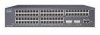
Chapter 1 Product Overview Figure 1-1 Catalyst 2900 Series XL Switches Version Number Description WS-C2912-LRE-XL 4 fixed autosensing 10/100 ports INPUT OUTPUT PWR PWR RESET TEMP FAN 9X 10X 11X 12X 12 LRE ports Cisco RPS 300 WS-C2924-LRE-XL 4 fixed autosensing 10/100 ports 24 LRE ports INPUT OUTPUT PWR PWR... 4 5 100BASE-FX 6 7 8 9 10 11 12 WS-C2924M-XL WS-C2924M-XLEM-DC 24 fixed autosensing 10/100 ports 2 expansion slots 12 MODE 1X 2X 3X Catalyst 2900 SERIES XL 4X 5X 6X 7X 8X 9X 10X 11X 100BaseFX 12X 13X 14X 15X 16X 17X 18X 19X 20X 21X 22X 23X 24X...
Chapter 1 Product Overview Figure 1-1 Catalyst 2900 Series XL Switches Version Number Description WS-C2912-LRE-XL 4 fixed autosensing 10/100 ports INPUT OUTPUT PWR PWR RESET TEMP FAN 9X 10X 11X 12X 12 LRE ports Cisco RPS 300 WS-C2924-LRE-XL 4 fixed autosensing 10/100 ports 24 LRE ports INPUT OUTPUT PWR PWR... 4 5 100BASE-FX 6 7 8 9 10 11 12 WS-C2924M-XL WS-C2924M-XLEM-DC 24 fixed autosensing 10/100 ports 2 expansion slots 12 MODE 1X 2X 3X Catalyst 2900 SERIES XL 4X 5X 6X 7X 8X 9X 10X 11X 100BaseFX 12X 13X 14X 15X 16X 17X 18X 19X 20X 21X 22X 23X 24X...

Hardware Installation Guide
Page 24
...Management Interface Options You can configure and monitor individual switches and switch clusters by using these front-panel components. You can fully configure and monitor a standalone switch, a specific cluster member, or an entire switch cluster. All switches have up to twenty-four 10/100 ports (... Ethernet ports (See Figure 1-4). You can have a set of LEDs and a Mode button. Front-Panel Description Depending on the switch. Catalyst 2900 Series XL Hardware Installation Guide 1-4 78-6461-04 This section describes these interfaces: • Cluster Management Suite (CMS)-CMS ...
...Management Interface Options You can configure and monitor individual switches and switch clusters by using these front-panel components. You can fully configure and monitor a standalone switch, a specific cluster member, or an entire switch cluster. All switches have up to twenty-four 10/100 ports (... Ethernet ports (See Figure 1-4). You can have a set of LEDs and a Mode button. Front-Panel Description Depending on the switch. Catalyst 2900 Series XL Hardware Installation Guide 1-4 78-6461-04 This section describes these interfaces: • Cluster Management Suite (CMS)-CMS ...

Hardware Installation Guide
Page 26
...-45 connectors and Category 3, 4, or 5 cabling • 100BASE-TX-compatible devices, such as high-speed workstations, Cisco IP Phones, servers, hubs, routers, and other switches through , twisted-pair cable. Refer to the Catalyst 2900 Series XL and Catalyst 3500 Series XL Software Configuration Guide for the cables are described in any compatible network device...
...-45 connectors and Category 3, 4, or 5 cabling • 100BASE-TX-compatible devices, such as high-speed workstations, Cisco IP Phones, servers, hubs, routers, and other switches through , twisted-pair cable. Refer to the Catalyst 2900 Series XL and Catalyst 3500 Series XL Software Configuration Guide for the cables are described in any compatible network device...

Hardware Installation Guide
Page 27
...of up to 1352 feet (412 meters). • If the switch port and the port on the same Catalyst 2900 LRE XL switch, and you can be connected to the patch panel through a private branch exchange (PBX) switch, a Cisco LRE 48 POTS Splitter can hot swap the CPE devices without powering ...down the switch or disrupting the other switch ports. Chapter 1 Product Overview ...
...of up to 1352 feet (412 meters). • If the switch port and the port on the same Catalyst 2900 LRE XL switch, and you can be connected to the patch panel through a private branch exchange (PBX) switch, a Cisco LRE 48 POTS Splitter can hot swap the CPE devices without powering ...down the switch or disrupting the other switch ports. Chapter 1 Product Overview ...

Hardware Installation Guide
Page 28
...kHz frequency range. Each module port is internally switched to share lines with LRE signals. For more information about homologated POTS splitters, contact your Cisco sales representative. Digital telephones connected to the Installation Notes for the Catalyst 2900 XL hot-swappable modules. Module Slots The...X2922-XL WS-X2922-XL-V WS-X2924-XL-V Catalyst 2900 Series XL Hardware Installation Guide 1-8 78-6461-04 For more information about the Cisco LRE 48 POTS Splitter (PS-1M-LRE-48), refer to digital PBX switches that the module slots support. Front-Panel Description Chapter...
...kHz frequency range. Each module port is internally switched to share lines with LRE signals. For more information about homologated POTS splitters, contact your Cisco sales representative. Digital telephones connected to the Installation Notes for the Catalyst 2900 XL hot-swappable modules. Module Slots The...X2922-XL WS-X2922-XL-V WS-X2924-XL-V Catalyst 2900 Series XL Hardware Installation Guide 1-8 78-6461-04 For more information about the Cisco LRE 48 POTS Splitter (PS-1M-LRE-48), refer to digital PBX switches that the module slots support. Front-Panel Description Chapter...

Software Guide
Page 220
... 10 Configuring VLANs Figure 10-2 Switch-to-Phone Connections Cisco IP Phone 7960 Catalyst switch 10/100 module Phone ASIC P2 P1 3-port P3 switch Access port Workstation/PC 38204 When the IP phone connects to a 10/100 port on the Catalyst 4500 series switch, the access port (PC-to... are 802.1Q frames carrying VLAN ID 0 and Layer 2 CoS set port auxiliaryvlan mod[/port] dot1p command) 10-14 Catalyst 4500 Series, Catalyst 2948G, Catalyst 2980G Switches Software Configuration Guide-Release 8.1 78-15486-01 A new VLAN means a new subnet and a new set port auxiliaryvlan mod[/port] ...
... 10 Configuring VLANs Figure 10-2 Switch-to-Phone Connections Cisco IP Phone 7960 Catalyst switch 10/100 module Phone ASIC P2 P1 3-port P3 switch Access port Workstation/PC 38204 When the IP phone connects to a 10/100 port on the Catalyst 4500 series switch, the access port (PC-to... are 802.1Q frames carrying VLAN ID 0 and Layer 2 CoS set port auxiliaryvlan mod[/port] dot1p command) 10-14 Catalyst 4500 Series, Catalyst 2948G, Catalyst 2980G Switches Software Configuration Guide-Release 8.1 78-15486-01 A new VLAN means a new subnet and a new set port auxiliaryvlan mod[/port] ...

Software Guide
Page 431
... variable power supplies, consider the required system power (see Table 28-2 on the circuit. Table 28-3 lists the switch components that is no power on page 28-9). 78-15486-01 Catalyst 4500 Series, Catalyst 2948G, Catalyst 2980G Switches Software Configuration Guide-Release 8.1 28-11 To determine the power requirements for each port; The powered device can...
... variable power supplies, consider the required system power (see Table 28-2 on the circuit. Table 28-3 lists the switch components that is no power on page 28-9). 78-15486-01 Catalyst 4500 Series, Catalyst 2948G, Catalyst 2980G Switches Software Configuration Guide-Release 8.1 28-11 To determine the power requirements for each port; The powered device can...
Software Guide
Page 434
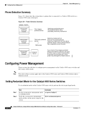
... to redundant mode. Supervisor engine will not discover the powered device. Setting Redundant Mode for the switch. 28-14 Catalyst 4500 Series, Catalyst 2948G, Catalyst 2980G Switches Software Configuration Guide-Release 8.1 78-15486-01 Figure 28-1 Power Detection Summary Catalyst Switch Inline power switching module Cisco legacy powered device Switching module discovers the powered device using proprietary discovery mechanism Inline power...
... to redundant mode. Supervisor engine will not discover the powered device. Setting Redundant Mode for the switch. 28-14 Catalyst 4500 Series, Catalyst 2948G, Catalyst 2980G Switches Software Configuration Guide-Release 8.1 78-15486-01 Figure 28-1 Power Detection Summary Catalyst Switch Inline power switching module Cisco legacy powered device Switching module discovers the powered device using proprietary discovery mechanism Inline power...

Software Guide
Page 452
... None specified 5 sec 0 (servers not marked dead) 2 times 30-8 Catalyst 4500 Series, Catalyst 2948G, Catalyst 2980G Switches Software Configuration Guide-Release 8.1 78-15486-01 Configuring Authentication Chapter 30 Configuring Switch Access Using AAA Figure 30-2 Non-Kerberized Telnet Connection Host (Telnet client) Kerberos server (contains KDC) 1 2 3 Catalyst switch 55510 Configuring Authentication The following sections describe how to configure...
... None specified 5 sec 0 (servers not marked dead) 2 times 30-8 Catalyst 4500 Series, Catalyst 2948G, Catalyst 2980G Switches Software Configuration Guide-Release 8.1 78-15486-01 Configuring Authentication Chapter 30 Configuring Switch Access Using AAA Figure 30-2 Non-Kerberized Telnet Connection Host (Telnet client) Kerberos server (contains KDC) 1 2 3 Catalyst switch 55510 Configuring Authentication The following sections describe how to configure...

Software Guide
Page 500
... 802.1x uses the term supplicant for Ethernet and sent to the host. 31-2 Catalyst 4500 Series, Catalyst 2948G, Catalyst 2980G Switches Software Configuration Guide-Release 8.1 78-15486-01 When the switch receives Extensible Authentication Protocol over LAN (EAPOL) frames and relays them to the authentication ...we use host instead of supplicant because host is used in Cisco Secure Access Control Server version 3.0. RADIUS operates in a client/server model in both directions or just incoming traffic. When the switch receives frames from the authentication server, the server's frame header ...
... 802.1x uses the term supplicant for Ethernet and sent to the host. 31-2 Catalyst 4500 Series, Catalyst 2948G, Catalyst 2980G Switches Software Configuration Guide-Release 8.1 78-15486-01 When the switch receives Extensible Authentication Protocol over LAN (EAPOL) frames and relays them to the authentication ...we use host instead of supplicant because host is used in Cisco Secure Access Control Server version 3.0. RADIUS operates in a client/server model in both directions or just incoming traffic. When the switch receives frames from the authentication server, the server's frame header ...

Software Guide
Page 501
...-2 Message Exchange Supplicant Catalyst switch Authentication server (RADIUS) EAPOL-Start EAP-Request/Identity EAP-Response/Identity EAP-Request/OTP EAP-Response/OTP EAP-Success RADIUS Access-Request RADIUS Access-Challenge RADIUS Access-Request RADIUS Access-Accept Port Authorized EAPOL-Logoff Port Unauthorized 79598 78-15486-01 Catalyst 4500 Series, Catalyst 2948G, Catalyst 2980G Switches Software Configuration Guide...
...-2 Message Exchange Supplicant Catalyst switch Authentication server (RADIUS) EAPOL-Start EAP-Request/Identity EAP-Response/Identity EAP-Request/OTP EAP-Response/OTP EAP-Success RADIUS Access-Request RADIUS Access-Challenge RADIUS Access-Request RADIUS Access-Accept Port Authorized EAPOL-Logoff Port Unauthorized 79598 78-15486-01 Catalyst 4500 Series, Catalyst 2948G, Catalyst 2980G Switches Software Configuration Guide...


