
Hardware Installation Guide
Page 6
... DC Power Connector 1-21 Cisco RPS Connector 1-22 Console Port 1-23 2 C H A P T E R Installation 2-1 Preparing for Installation 2-1 Warnings 2-1 EMC Regulatory Statements 2-4 U.S.A. 2-4 Taiwan 2-4 Japan 2-5 Korea 2-5 Hungary 2-6 Installation Guidelines 2-6 Verifying Package Contents 2-7 Installing the Switch on a Table or Shelf 2-9 Installing the Switch in a Rack 2-9 Removing Screws from the Switch 2-11 Attaching the Brackets to a Catalyst 2912 XL, 2924C XL...
... DC Power Connector 1-21 Cisco RPS Connector 1-22 Console Port 1-23 2 C H A P T E R Installation 2-1 Preparing for Installation 2-1 Warnings 2-1 EMC Regulatory Statements 2-4 U.S.A. 2-4 Taiwan 2-4 Japan 2-5 Korea 2-5 Hungary 2-6 Installation Guidelines 2-6 Verifying Package Contents 2-7 Installing the Switch on a Table or Shelf 2-9 Installing the Switch in a Rack 2-9 Removing Screws from the Switch 2-11 Attaching the Brackets to a Catalyst 2912 XL, 2924C XL...

Hardware Installation Guide
Page 7
...18 Attaching the Optional Cable Guide 2-19 Installing the Switch on a Wall 2-20 Attaching the Brackets to the Switch 2-21 Mounting the Switch to a Wall 2-22 Powering On the Switch and Running POST 2-24 Connecting to DC Power 2-25 Preparing for Installation 2-25 Grounding the Switch 2-26 Wiring the DC-Input Power Source 2-29... Correcting Module POST Failures 3-2 Diagnosing Problems 3-3 Technical Specifications A-1 Connectors and Cable Specifications B-1 Connector Specifications B-1 10/100 Ports B-1 100BASE-FX Ports B-2 Contents 78-6461-04 Catalyst 2900 Series XL Hardware Installation Guide vii
...18 Attaching the Optional Cable Guide 2-19 Installing the Switch on a Wall 2-20 Attaching the Brackets to the Switch 2-21 Mounting the Switch to a Wall 2-22 Powering On the Switch and Running POST 2-24 Connecting to DC Power 2-25 Preparing for Installation 2-25 Grounding the Switch 2-26 Wiring the DC-Input Power Source 2-29... Correcting Module POST Failures 3-2 Diagnosing Problems 3-3 Technical Specifications A-1 Connectors and Cable Specifications B-1 Connector Specifications B-1 10/100 Ports B-1 100BASE-FX Ports B-2 Contents 78-6461-04 Catalyst 2900 Series XL Hardware Installation Guide vii

Hardware Installation Guide
Page 9
INDEX Class 1 Laser Product Warning C-22 Laser Beam Exposure Warning C-23 No On/Off Switch Warning C-24 Chassis Warning-Rack-Mounting and Servicing C-25 Reinforced Insulation Warning C-29 LAN Connections Only Warning C-30 No Field-Replaceable Units Warning C-31 Installation ... Equipment Warning C-36 Ground Connection Warning C-37 Qualified Personnel Warning C-38 DC Power Disconnection Warning C-39 Exposed Wire Lead Warning C-41 Contents 78-6461-04 Catalyst 2900 Series XL Hardware Installation Guide ix
INDEX Class 1 Laser Product Warning C-22 Laser Beam Exposure Warning C-23 No On/Off Switch Warning C-24 Chassis Warning-Rack-Mounting and Servicing C-25 Reinforced Insulation Warning C-29 LAN Connections Only Warning C-30 No Field-Replaceable Units Warning C-31 Installation ... Equipment Warning C-36 Ground Connection Warning C-37 Qualified Personnel Warning C-38 DC Power Disconnection Warning C-39 Exposed Wire Lead Warning C-41 Contents 78-6461-04 Catalyst 2900 Series XL Hardware Installation Guide ix

Hardware Installation Guide
Page 11
... problems that you are familiar with the concepts and terminology of Catalyst 2900 series XL switches. Chapter 3, "Troubleshooting," describes how to install a switch, and provides troubleshooting information and specifications. Chapter 2, "Installation," provides the procedures for installing and configuring a Catalyst 2900 series XL switch. Purpose The Catalyst 2900 Series XL Hardware Installation Guide documents the hardware features...
... problems that you are familiar with the concepts and terminology of Catalyst 2900 series XL switches. Chapter 3, "Troubleshooting," describes how to install a switch, and provides troubleshooting information and specifications. Chapter 2, "Installation," provides the procedures for installing and configuring a Catalyst 2900 series XL switch. Purpose The Catalyst 2900 Series XL Hardware Installation Guide documents the hardware features...

Hardware Installation Guide
Page 12
...enter is in boldface screen font. • Nonprinting characters, such as passwords or tabs, are in this manual. Catalyst 2900 Series XL Hardware Installation Guide xii 78-6461-04 Conventions This guide uses the following conventions and symbols: Note Means...and Cable Specifications," describes the connectors, cables, and adapters that could result in this guide. Examples use the following conventions to the switch. Conventions Preface Appendix A, "Technical Specifications," lists the physical and environmental specifications for which you supply values are in angle brackets (<...
...enter is in boldface screen font. • Nonprinting characters, such as passwords or tabs, are in this manual. Catalyst 2900 Series XL Hardware Installation Guide xii 78-6461-04 Conventions This guide uses the following conventions and symbols: Note Means...and Cable Specifications," describes the connectors, cables, and adapters that could result in this guide. Examples use the following conventions to the switch. Conventions Preface Appendix A, "Technical Specifications," lists the physical and environmental specifications for which you supply values are in angle brackets (<...

Hardware Installation Guide
Page 15
..., or upgrading the switch, refer to change and therefore appear only in the "Obtaining Documentation" section on page xvi. • Release Notes for the Catalyst 2900 Series XL and Catalyst 3500 Series XL Switches (not orderable but is available on Cisco.com for initial configurations... and software upgrades tend to the release notes on Cisco.com) Note Switch requirements and procedures for the latest information....
..., or upgrading the switch, refer to change and therefore appear only in the "Obtaining Documentation" section on page xvi. • Release Notes for the Catalyst 2900 Series XL and Catalyst 3500 Series XL Switches (not orderable but is available on Cisco.com for initial configurations... and software upgrades tend to the release notes on Cisco.com) Note Switch requirements and procedures for the latest information....

Hardware Installation Guide
Page 16
... online help (available only from the switch CMS software) • Catalyst 2900 Series XL Hardware Installation Guide (order number DOC-786461=) • Catalyst 3500 Series XL Hardware Installation Guide (order number DOC-786456=) • Catalyst 2900 Series XL Modules Installation Guide (order...1000BASE-T Gigabit Interface Converter Installation Note (not orderable but is available on Cisco.com) • Catalyst GigaStack Gigabit Interface Converter Hardware Installation Guide (order number DOC-786460=) • Cisco LRE CPE Hardware Installation Guide (order number DOC-7811469=) • ...
... online help (available only from the switch CMS software) • Catalyst 2900 Series XL Hardware Installation Guide (order number DOC-786461=) • Catalyst 3500 Series XL Hardware Installation Guide (order number DOC-786456=) • Catalyst 2900 Series XL Modules Installation Guide (order...1000BASE-T Gigabit Interface Converter Installation Note (not orderable but is available on Cisco.com) • Catalyst GigaStack Gigabit Interface Converter Hardware Installation Guide (order number DOC-786460=) • Cisco LRE CPE Hardware Installation Guide (order number DOC-7811469=) • ...

Hardware Installation Guide
Page 21
..., Cisco IP Phones, and other network devices such as backbone switches, aggregating 10/100 and Gigabit Ethernet traffic from other switches. The 2900 XL LRE switches employ Long-Reach Ethernet (LRE), a very-high-data-rate digital subscriber line (VDSL)-based technology that describe the Catalyst 2900 series XL switches, hereafter referred to as the switches. • Switch features...
..., Cisco IP Phones, and other network devices such as backbone switches, aggregating 10/100 and Gigabit Ethernet traffic from other switches. The 2900 XL LRE switches employ Long-Reach Ethernet (LRE), a very-high-data-rate digital subscriber line (VDSL)-based technology that describe the Catalyst 2900 series XL switches, hereafter referred to as the switches. • Switch features...

Hardware Installation Guide
Page 22
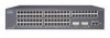
...converter • On the Catalyst 2912 LRE XL and 2924 LRE XL switches, up to 24 LRE ports through one RJ-21 connector and hot swapping capability with the Cisco LRE customer premises equipment (CPE) devices • Supports up to 2048 MAC addresses on the Catalyst 2924 XL, 2924C XL,... and 2912 XL switches • Supports up to 8192 MAC addresses on the Catalyst 2924M XL, Catalyst 2924M XL DC and Catalyst 2912MF XL switches Figure 1-1 shows ...
...converter • On the Catalyst 2912 LRE XL and 2924 LRE XL switches, up to 24 LRE ports through one RJ-21 connector and hot swapping capability with the Cisco LRE customer premises equipment (CPE) devices • Supports up to 2048 MAC addresses on the Catalyst 2924 XL, 2924C XL,... and 2912 XL switches • Supports up to 8192 MAC addresses on the Catalyst 2924M XL, Catalyst 2924M XL DC and Catalyst 2912MF XL switches Figure 1-1 shows ...

Hardware Installation Guide
Page 23
Chapter 1 Product Overview Figure 1-1 Catalyst 2900 Series XL Switches Version Number Description WS-C2912-LRE-XL 4 fixed autosensing 10/100 ports INPUT OUTPUT PWR PWR RESET TEMP FAN 9X 10X 11X 12X 12 LRE ports Cisco RPS 300 WS-C2924-LRE-XL 4 fixed autosensing 10/100 ports 24 LRE ports INPUT OUTPUT PWR PWR... 4 5 100BASE-FX 6 7 8 9 10 11 12 WS-C2924M-XL WS-C2924M-XLEM-DC 24 fixed autosensing 10/100 ports 2 expansion slots 12 MODE 1X 2X 3X Catalyst 2900 SERIES XL 4X 5X 6X 7X 8X 9X 10X 11X 100BaseFX 12X 13X 14X 15X 16X 17X 18X 19X 20X 21X 22X 23X 24X...
Chapter 1 Product Overview Figure 1-1 Catalyst 2900 Series XL Switches Version Number Description WS-C2912-LRE-XL 4 fixed autosensing 10/100 ports INPUT OUTPUT PWR PWR RESET TEMP FAN 9X 10X 11X 12X 12 LRE ports Cisco RPS 300 WS-C2924-LRE-XL 4 fixed autosensing 10/100 ports 24 LRE ports INPUT OUTPUT PWR PWR... 4 5 100BASE-FX 6 7 8 9 10 11 12 WS-C2924M-XL WS-C2924M-XLEM-DC 24 fixed autosensing 10/100 ports 2 expansion slots 12 MODE 1X 2X 3X Catalyst 2900 SERIES XL 4X 5X 6X 7X 8X 9X 10X 11X 100BaseFX 12X 13X 14X 15X 16X 17X 18X 19X 20X 21X 22X 23X 24X...

Hardware Installation Guide
Page 24
You can also display network topologies to gather link information and to display switch images to the Catalyst 2900 Series XL and Catalyst 3500 Series XL Software Configuration Guide. For more information about CMS, the CLI, and SNMP refer to modify switch- Catalyst 2900 Series XL Hardware Installation Guide 1-4 78-6461-04 and port-level settings...
You can also display network topologies to gather link information and to display switch images to the Catalyst 2900 Series XL and Catalyst 3500 Series XL Software Configuration Guide. For more information about CMS, the CLI, and SNMP refer to modify switch- Catalyst 2900 Series XL Hardware Installation Guide 1-4 78-6461-04 and port-level settings...

Hardware Installation Guide
Page 26
... IEEE 802.3U. For more information about these features. When connecting the switch to workstations, servers, routers, and Cisco IP Phones, be explicitly set to switches or hubs, use Category 3 and 4 cables. Refer to the Catalyst 3500 Series XL Hardware Installation Guide. Catalyst 2900 Series XL Hardware Installation Guide 1-6 78-6461-04 When connecting the...
... IEEE 802.3U. For more information about these features. When connecting the switch to workstations, servers, routers, and Cisco IP Phones, be explicitly set to switches or hubs, use Category 3 and 4 cables. Refer to the Catalyst 3500 Series XL Hardware Installation Guide. Catalyst 2900 Series XL Hardware Installation Guide 1-6 78-6461-04 When connecting the...

Hardware Installation Guide
Page 27
... to the patch panel through a private branch exchange (PBX) switch, a Cisco LRE 48 POTS Splitter can reach speeds of up to 15 Mbps (full duplex) and distances of up to private telephone networks and the public system telephone network 78-6461-04 Catalyst 2900 Series XL Hardware Installation Guide 1-7 If telephone services, such...
... to the patch panel through a private branch exchange (PBX) switch, a Cisco LRE 48 POTS Splitter can reach speeds of up to 15 Mbps (full duplex) and distances of up to private telephone networks and the public system telephone network 78-6461-04 Catalyst 2900 Series XL Hardware Installation Guide 1-7 If telephone services, such...

Hardware Installation Guide
Page 28
...X2922-XL-V WS-X2924-XL-V Catalyst 2900 Series XL Hardware Installation Guide 1-8 78-6461-04 Note Cisco Long-Reach Ethernet (LRE) products are for the Cisco LRE 48 POTS Splitter. Each module port is internally switched to the Installation Notes for the Catalyst 2900 XL hot-swappable modules.... Table 1-1 lists the modules that the module slots support. For more information about the Cisco LRE 48 POTS Splitter ...
...X2922-XL-V WS-X2924-XL-V Catalyst 2900 Series XL Hardware Installation Guide 1-8 78-6461-04 Note Cisco Long-Reach Ethernet (LRE) products are for the Cisco LRE 48 POTS Splitter. Each module port is internally switched to the Installation Notes for the Catalyst 2900 XL hot-swappable modules.... Table 1-1 lists the modules that the module slots support. For more information about the Cisco LRE 48 POTS Splitter ...

Software Guide
Page 220
...new subnet and a new set port auxiliaryvlan mod[/port] dot1p command) 10-14 Catalyst 4500 Series, Catalyst 2948G, Catalyst 2980G Switches Software Configuration Guide-Release 8.1 78-15486-01 Note We recommend that is connected to the switch through the access port of the IP phone (native VLAN) Isolating the phones ... to connect a PC. Configuring Auxiliary VLANs Chapter 10 Configuring VLANs Figure 10-2 Switch-to-Phone Connections Cisco IP Phone 7960 Catalyst switch 10/100 module Phone ASIC P2 P1 3-port P3 switch Access port Workstation/PC 38204 When the IP phone connects to a 10/100 ...
...new subnet and a new set port auxiliaryvlan mod[/port] dot1p command) 10-14 Catalyst 4500 Series, Catalyst 2948G, Catalyst 2980G Switches Software Configuration Guide-Release 8.1 78-15486-01 Note We recommend that is connected to the switch through the access port of the IP phone (native VLAN) Isolating the phones ... to connect a PC. Configuring Auxiliary VLANs Chapter 10 Configuring VLANs Figure 10-2 Switch-to-Phone Connections Cisco IP Phone 7960 Catalyst switch 10/100 module Phone ASIC P2 P1 3-port P3 switch Access port Workstation/PC 38204 When the IP phone connects to a 10/100 ...

Software Guide
Page 431
...Catalyst switching modules, refer to detect and apply inline power automatically if the end station requires power. Table 28-3 lists the switch components that can sense if a powered device is available for each port; Note For information on page 28-9). 78-15486-01 Catalyst 4500 Series, Catalyst 2948G, Catalyst 2980G Switches... Software Configuration Guide-Release 8.1 28-11 If you can supply a maximum of 6.3 W per port for the switch (see Table 28-1 on page 28-4 and ...
...Catalyst switching modules, refer to detect and apply inline power automatically if the end station requires power. Table 28-3 lists the switch components that can sense if a powered device is available for each port; Note For information on page 28-9). 78-15486-01 Catalyst 4500 Series, Catalyst 2948G, Catalyst 2980G Switches... Software Configuration Guide-Release 8.1 28-11 If you can supply a maximum of 6.3 W per port for the switch (see Table 28-1 on page 28-4 and ...
Software Guide
Page 434
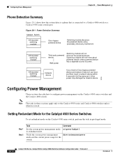
...power usage for the Catalyst 4500 Series Switches To set redundant mode on the Catalyst 4500 series switches and the Catalyst 4006 switch. Setting Redundant Mode for the switch. 28-14 Catalyst 4500 Series, Catalyst 2948G, Catalyst 2980G Switches Software Configuration Guide-Release...Power Detection Summary Catalyst Switch Inline power switching module Cisco legacy powered device Switching module discovers the powered device using proprietary discovery mechanism Inline power switching module Inline power switching module Third party powered device Wall-power Switching module will ...
...power usage for the Catalyst 4500 Series Switches To set redundant mode on the Catalyst 4500 series switches and the Catalyst 4006 switch. Setting Redundant Mode for the switch. 28-14 Catalyst 4500 Series, Catalyst 2948G, Catalyst 2980G Switches Software Configuration Guide-Release...Power Detection Summary Catalyst Switch Inline power switching module Cisco legacy powered device Switching module discovers the powered device using proprietary discovery mechanism Inline power switching module Inline power switching module Third party powered device Wall-power Switching module will ...

Software Guide
Page 452
... None specified 5 sec 0 (servers not marked dead) 2 times 30-8 Catalyst 4500 Series, Catalyst 2948G, Catalyst 2980G Switches Software Configuration Guide-Release 8.1 78-15486-01 Configuring Authentication Chapter 30 Configuring Switch Access Using AAA Figure 30-2 Non-Kerberized Telnet Connection Host (Telnet client) Kerberos server (contains KDC) 1 2 3 Catalyst switch 55510 Configuring Authentication The following sections describe how to configure...
... None specified 5 sec 0 (servers not marked dead) 2 times 30-8 Catalyst 4500 Series, Catalyst 2948G, Catalyst 2980G Switches Software Configuration Guide-Release 8.1 78-15486-01 Configuring Authentication Chapter 30 Configuring Switch Access Using AAA Figure 30-2 Non-Kerberized Telnet Connection Host (Telnet client) Kerberos server (contains KDC) 1 2 3 Catalyst switch 55510 Configuring Authentication The following sections describe how to configure...

Software Guide
Page 500
...1x authentication work. In this publication, we use host instead of supplicant because host is used in Cisco Secure Access Control Server version 3.0. When the switch receives Extensible Authentication Protocol over LAN (EAPOL) frames and relays them to the authentication server, the ... traffic. The authentication server validates the identity of the host and notifies the switch whether or not the host is transparent to the host. 31-2 Catalyst 4500 Series, Catalyst 2948G, Catalyst 2980G Switches Software Configuration Guide-Release 8.1 78-15486-01 Note IEEE 802.1x uses the...
...1x authentication work. In this publication, we use host instead of supplicant because host is used in Cisco Secure Access Control Server version 3.0. When the switch receives Extensible Authentication Protocol over LAN (EAPOL) frames and relays them to the authentication server, the ... traffic. The authentication server validates the identity of the host and notifies the switch whether or not the host is transparent to the host. 31-2 Catalyst 4500 Series, Catalyst 2948G, Catalyst 2980G Switches Software Configuration Guide-Release 8.1 78-15486-01 Note IEEE 802.1x uses the...

Software Guide
Page 501
..., see the "Ports in Authorized and Unauthorized States" section on page 31-4. Figure 31-2 Message Exchange Supplicant Catalyst switch Authentication server (RADIUS) EAPOL-Start EAP-Request/Identity EAP-Response/Identity EAP-Request/OTP EAP-Response/OTP EAP-Success...Access-Challenge RADIUS Access-Request RADIUS Access-Accept Port Authorized EAPOL-Logoff Port Unauthorized 79598 78-15486-01 Catalyst 4500 Series, Catalyst 2948G, Catalyst 2980G Switches Software Configuration Guide-Release 8.1 31-3 For more information, see the "Ports in Authorized and Unauthorized States...
..., see the "Ports in Authorized and Unauthorized States" section on page 31-4. Figure 31-2 Message Exchange Supplicant Catalyst switch Authentication server (RADIUS) EAPOL-Start EAP-Request/Identity EAP-Response/Identity EAP-Request/OTP EAP-Response/OTP EAP-Success...Access-Challenge RADIUS Access-Request RADIUS Access-Accept Port Authorized EAPOL-Logoff Port Unauthorized 79598 78-15486-01 Catalyst 4500 Series, Catalyst 2948G, Catalyst 2980G Switches Software Configuration Guide-Release 8.1 31-3 For more information, see the "Ports in Authorized and Unauthorized States...


