Software Configuration Guide
Page 35
Layer 3 IP version 6 (IPv6) packets are treated as non-IP packets. Table 1-1 Switches Supported Switch Catalyst 2950-12 Catalyst 2950-24 Catalyst 2950C-24 Catalyst 2950G-12-EI Catalyst 2950G-24-EI Catalyst 2950G-24-EI-DC Catalyst 2950G-48-EI Catalyst 2950ST-8 LRE Catalyst 2950ST-24 LRE Catalyst 2950ST-24 LRE 997 Catalyst 2950SX-24 Catalyst 2950SX-48-SI Catalyst 2950T-24 Catalyst 2950T-48-SI Software Image SI1 SI EI2 EI EI EI EI EI EI EI...
Layer 3 IP version 6 (IPv6) packets are treated as non-IP packets. Table 1-1 Switches Supported Switch Catalyst 2950-12 Catalyst 2950-24 Catalyst 2950C-24 Catalyst 2950G-12-EI Catalyst 2950G-24-EI Catalyst 2950G-24-EI-DC Catalyst 2950G-48-EI Catalyst 2950ST-8 LRE Catalyst 2950ST-24 LRE Catalyst 2950ST-24 LRE 997 Catalyst 2950SX-24 Catalyst 2950SX-48-SI Catalyst 2950T-24 Catalyst 2950T-48-SI Software Image SI1 SI EI2 EI EI EI EI EI EI EI...

Software Configuration Guide
Page 39
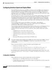
...Cisco IP Phones • VLAN 1 minimization to reduce the risk of spanning-tree loops or storms by allowing VLAN 1 to support the number of VLANs allowed by the IEEE 802.1Q standard (available only with appropriate network resources, traffic patterns, and bandwidth Note The Catalyst 2950-12, Catalyst 2950-24, Catalyst 2950SX-24, Catalyst 2950SX-48-SI, and Catalyst 2950T...-48-SI switches support only 64 port-based VLANs. • The switch supports up to 4094 VLAN ...
...Cisco IP Phones • VLAN 1 minimization to reduce the risk of spanning-tree loops or storms by allowing VLAN 1 to support the number of VLANs allowed by the IEEE 802.1Q standard (available only with appropriate network resources, traffic patterns, and bandwidth Note The Catalyst 2950-12, Catalyst 2950-24, Catalyst 2950SX-24, Catalyst 2950SX-48-SI, and Catalyst 2950T...-48-SI switches support only 64 port-based VLANs. • The switch supports up to 4094 VLAN ...
Software Configuration Guide
Page 250
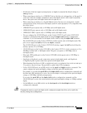
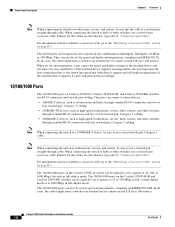
.... 11-10 Catalyst 2950 and Catalyst 2955 Switch Software Configuration Guide 78-11380-10 The fiber-optic SFP-module ports on Catalyst 2950 LRE, Catalyst 2950T-24, Catalyst 2950T-48-SI, and Catalyst 2955T-24 switches operate at 1000 Mbps in full-duplex mode. You can configure duplex mode on the 10/100/1000 ports on the Catalyst 2950 LRE, Catalyst 2950T-24, Catalyst 2950T-48-SI, and Catalyst 2955T-24 switches but cannot...
.... 11-10 Catalyst 2950 and Catalyst 2955 Switch Software Configuration Guide 78-11380-10 The fiber-optic SFP-module ports on Catalyst 2950 LRE, Catalyst 2950T-24, Catalyst 2950T-48-SI, and Catalyst 2955T-24 switches operate at 1000 Mbps in full-duplex mode. You can configure duplex mode on the 10/100/1000 ports on the Catalyst 2950 LRE, Catalyst 2950T-24, Catalyst 2950T-48-SI, and Catalyst 2955T-24 switches but cannot...
Software Configuration Guide
Page 251
... autonegotiate the speed and duplex settings as 10 Mbps and half duplex. • On the LRE ports on the Catalyst 2950T-24 and Catalyst 2950T-48-SI switches to autonegotiate the duplex mode by using the duplex auto interface configuration command, or you enter the speed 100 and ...Catalyst 2950 LRE or the Catalyst 2955T-12 switch can operate at 1000Mbps and in the duplex command. The 10/100/1000 ports on the Catalyst 2950T-48-SI switches support the half keyword when the interface speed is amber while STP reconfigures. • On the 10/100/1000 ports on the Catalyst 2950T-24 switches...
... autonegotiate the speed and duplex settings as 10 Mbps and half duplex. • On the LRE ports on the Catalyst 2950T-24 and Catalyst 2950T-48-SI switches to autonegotiate the duplex mode by using the duplex auto interface configuration command, or you enter the speed 100 and ...Catalyst 2950 LRE or the Catalyst 2955T-12 switch can operate at 1000Mbps and in the duplex command. The 10/100/1000 ports on the Catalyst 2950T-48-SI switches support the half keyword when the interface speed is amber while STP reconfigures. • On the 10/100/1000 ports on the Catalyst 2950T-24 switches...

Hardware Installation Guide
Page 22
.../100/1000 Ethernet ports, and 2 SFP module slots. (Two of the four uplink ports are active at one time.) Note See the Catalyst 2950 LRE switch release notes for the Catalyst 2950 LRE switches. - Catalyst 2950T-24 switch-24 10/100 Ethernet ports and 2 10/100/1000 Ethernet ports - For 100BASE-FX ports, supports only 100-Mbps and full-duplex settings...
.../100/1000 Ethernet ports, and 2 SFP module slots. (Two of the four uplink ports are active at one time.) Note See the Catalyst 2950 LRE switch release notes for the Catalyst 2950 LRE switches. - Catalyst 2950T-24 switch-24 10/100 Ethernet ports and 2 10/100/1000 Ethernet ports - For 100BASE-FX ports, supports only 100-Mbps and full-duplex settings...
Hardware Installation Guide
Page 27
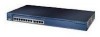
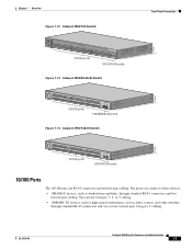
... these devices: • 10BASE-T devices, such as high-speed workstations, servers, hubs, routers, and other switches, through standard RJ-45 connectors and two twisted-pair cabling. OL-6156-01 Catalyst 2950 Switch Hardware Installation Guide 1-7 Chapter 1 Overview Figure 1-12 Catalyst 2950T-24 Switch Front-Panel Description 47337 SYST RPS STAT UTIL DUPLX SPEED MODE 1x 2x 3x 4x...
... these devices: • 10BASE-T devices, such as high-speed workstations, servers, hubs, routers, and other switches, through standard RJ-45 connectors and two twisted-pair cabling. OL-6156-01 Catalyst 2950 Switch Hardware Installation Guide 1-7 Chapter 1 Overview Figure 1-12 Catalyst 2950T-24 Switch Front-Panel Description 47337 SYST RPS STAT UTIL DUPLX SPEED MODE 1x 2x 3x 4x...
Hardware Installation Guide
Page 28
... are described in Appendix B, "Connectors and Cables." When connecting the switch to hubs or other switches, use a four twisted-pair, Category 5 cable. The 10/100/1000 ports on Catalyst 2950T-24, Catalyst 2950T-48-SI, and Catalyst 2950 LRE switches use RJ-45 connectors and twisted-pair cabling. If the attached device..."Connectors and Cables." For information on how to identify a crossover cable, go to the "Identifying a Crossover Cable" section on the Catalyst 2950T-24 switch can be explicitly set to operate at 10, 100, or 1000 Mbps, but only in full-duplex mode. In all cases, the...
... are described in Appendix B, "Connectors and Cables." When connecting the switch to hubs or other switches, use a four twisted-pair, Category 5 cable. The 10/100/1000 ports on Catalyst 2950T-24, Catalyst 2950T-48-SI, and Catalyst 2950 LRE switches use RJ-45 connectors and twisted-pair cabling. If the attached device..."Connectors and Cables." For information on how to identify a crossover cable, go to the "Identifying a Crossover Cable" section on the Catalyst 2950T-24 switch can be explicitly set to operate at 10, 100, or 1000 Mbps, but only in full-duplex mode. In all cases, the...

Hardware Installation Guide
Page 33
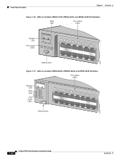
...Catalyst 2950-12, 2950-24, 2950C-24, 2950SX-24, and 2950T-24 switches • Figure 1-16 for the Catalyst 2950G-12-EI, 2950G-24-EI, and 2950G-24-EI-DC switches • Figure 1-17 for the Catalyst 2950G-48-EI, Catalyst 2950SX-48-SI, and Catalyst 2950T-48-SI switches • Figure 1-18 for the Catalyst 2950ST-8 LRE and 2950ST-24 LRE switches • Figure 1-19 for the Catalyst 2950ST-24 LRE 997 switches...CLI) to configure and to monitor switch activity and performance. Figure 1-15 LEDs on Catalyst 2950-12, 2950-24, 2950C-24, 2950SX-24, and 2950T-24 Switches RPS LED Port status LEDs System ...
...Catalyst 2950-12, 2950-24, 2950C-24, 2950SX-24, and 2950T-24 switches • Figure 1-16 for the Catalyst 2950G-12-EI, 2950G-24-EI, and 2950G-24-EI-DC switches • Figure 1-17 for the Catalyst 2950G-48-EI, Catalyst 2950SX-48-SI, and Catalyst 2950T-48-SI switches • Figure 1-18 for the Catalyst 2950ST-8 LRE and 2950ST-24 LRE switches • Figure 1-19 for the Catalyst 2950ST-24 LRE 997 switches...CLI) to configure and to monitor switch activity and performance. Figure 1-15 LEDs on Catalyst 2950-12, 2950-24, 2950C-24, 2950SX-24, and 2950T-24 Switches RPS LED Port status LEDs System ...
Hardware Installation Guide
Page 34
..., 2950G-24-EI, and 2950G-24-EI-DC Switches RPS LED Port status LEDs 65395 System LED Port mode LEDs SYST RPS STAT UTIL DUPLX SPEED MODE 1 1X 23 45 67 8 9 10 11 12 11X 2X 12X Mode button Figure 1-17 LEDs on Catalyst 2950G-48-EI, 2950SX-48-SI, and 2950T-48-SI Switches Port... status LEDs System LED RPS LED Port mode LEDs SYST RPS STAT UTIL DUPLX SPEED MODE 1 1X 23 45 67 89 10 11 12 13 14 15 16 15X 2X 16X Mode button 65508 1-14 Catalyst 2950 Switch Hardware Installation Guide OL-6156-01
..., 2950G-24-EI, and 2950G-24-EI-DC Switches RPS LED Port status LEDs 65395 System LED Port mode LEDs SYST RPS STAT UTIL DUPLX SPEED MODE 1 1X 23 45 67 8 9 10 11 12 11X 2X 12X Mode button Figure 1-17 LEDs on Catalyst 2950G-48-EI, 2950SX-48-SI, and 2950T-48-SI Switches Port... status LEDs System LED RPS LED Port mode LEDs SYST RPS STAT UTIL DUPLX SPEED MODE 1 1X 23 45 67 89 10 11 12 13 14 15 16 15X 2X 16X Mode button 65508 1-14 Catalyst 2950 Switch Hardware Installation Guide OL-6156-01
Hardware Installation Guide
Page 39
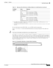
... do not give utilization status. If all LEDs on a Catalyst 2950-12, 2950-24, 2950C-24, 2950SX-24, or 2950T-24 switch are green (no amber showing), the switch is using 50 percent or more than 25 but less than 0.0488 percent of the total bandwidth. (See Figure 1-20 and Figure 1-...DUPLX SPEED MODE 1x 2x 3x 4x 5x 6x 7x 8x 10Base-T / 100Base-TX 9x 10x 11x 12x Catalyst 2950 SERIES 47267 0-0.0487%+ 6.25-12.4%+ 12.5-24%+ 25-49%+ 50%+ OL-6156-01 Catalyst 2950 Switch Hardware Installation Guide 1-19 Chapter 1 Overview Front-Panel Description Table 1-7 Meaning of Port LED Colors in ...
... do not give utilization status. If all LEDs on a Catalyst 2950-12, 2950-24, 2950C-24, 2950SX-24, or 2950T-24 switch are green (no amber showing), the switch is using 50 percent or more than 25 but less than 0.0488 percent of the total bandwidth. (See Figure 1-20 and Figure 1-...DUPLX SPEED MODE 1x 2x 3x 4x 5x 6x 7x 8x 10Base-T / 100Base-TX 9x 10x 11x 12x Catalyst 2950 SERIES 47267 0-0.0487%+ 6.25-12.4%+ 12.5-24%+ 25-49%+ 50%+ OL-6156-01 Catalyst 2950 Switch Hardware Installation Guide 1-19 Chapter 1 Overview Front-Panel Description Table 1-7 Meaning of Port LED Colors in ...
Hardware Installation Guide
Page 40
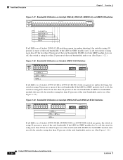
...LEDs for both GBIC module slots are off , the switch is using less than 50 percent of the total bandwidth. Front-Panel Description Chapter 1 Overview Figure 1-21 Bandwidth Utilization on Catalyst 2950-24, 2950C-24, 2950SX-24, and 2950T-24 Switches SYST RPS STAT UTIL DUPLX SPEED MODE 1x 2x 3x... 4x 5x 6x 7x 8x 10Base-T / 100Base-TX 9x 10x 11x 12x 13x 14x 15x 16x Catalyst 2950 SERIES 17x 18x 19x 20x 21x 22x...
...LEDs for both GBIC module slots are off , the switch is using less than 50 percent of the total bandwidth. Front-Panel Description Chapter 1 Overview Figure 1-21 Bandwidth Utilization on Catalyst 2950-24, 2950C-24, 2950SX-24, and 2950T-24 Switches SYST RPS STAT UTIL DUPLX SPEED MODE 1x 2x 3x... 4x 5x 6x 7x 8x 10Base-T / 100Base-TX 9x 10x 11x 12x 13x 14x 15x 16x Catalyst 2950 SERIES 17x 18x 19x 20x 21x 22x...

Hardware Installation Guide
Page 41
... 12005R@[email protected]~~ AC power connector [email protected]. Chapter 1 Overview Rear-Panel Description Figure 1-24 Bandwidth Utilization on Catalyst 2950G-48-EI, 2950SX-48-SI, and 2950T-48-SI Switches 65510 Catalyst 2950 12 1X 3 24 56 78 9 10 11 12 13 14 15 16 15X 17 18 17X 19 20 21 22 23... 24 25 26 27 28 29 31 31 32 31X 33 34 33X 35 36 37 38 39 40 41 42 43...
... 12005R@[email protected]~~ AC power connector [email protected]. Chapter 1 Overview Rear-Panel Description Figure 1-24 Bandwidth Utilization on Catalyst 2950G-48-EI, 2950SX-48-SI, and 2950T-48-SI Switches 65510 Catalyst 2950 12 1X 3 24 56 78 9 10 11 12 13 14 15 16 15X 17 18 17X 19 20 21 22 23... 24 25 26 27 28 29 31 31 32 31X 33 34 33X 35 36 37 38 39 40 41 42 43...
Hardware Installation Guide
Page 53
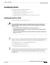
... 2-15 show the Catalyst 2950-24, 2950G-24-EI-DC, and 2950G-48-EI switches as shown in a Rack, page 2-16 3. Attaching the Optional Cable Guide, page 2-16 Note Installing a Catalyst 2950G-48-EI, Catalyst 2950SX-48-SI, or Catalyst 2950T-48-SI switch in a 19-, 23-, or 24-inch rack, follow these steps: 1. You can install other Catalyst 2950 switches in a rack as...
... 2-15 show the Catalyst 2950-24, 2950G-24-EI-DC, and 2950G-48-EI switches as shown in a Rack, page 2-16 3. Attaching the Optional Cable Guide, page 2-16 Note Installing a Catalyst 2950G-48-EI, Catalyst 2950SX-48-SI, or Catalyst 2950T-48-SI switch in a 19-, 23-, or 24-inch rack, follow these steps: 1. You can install other Catalyst 2950 switches in a rack as...
Hardware Installation Guide
Page 54
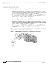
... 2-9. • When mounting a switch other than a Catalyst 2950G-48-EI, Catalyst 2950SX-48-SI, or Catalyst 2950T-48-SI switch in a 19-Inch Rack (Front Panel Forward) 45580 Number-8 Phillips flat-head screws SYST RPS STAT UTIL DUPLX SPEED MODE 1x 2x 3x 4x 5x Catalyst 2950 Switch Hardware Installation Guide 2-8 OL-6156-01 or 24-inch bracket to one...
... 2-9. • When mounting a switch other than a Catalyst 2950G-48-EI, Catalyst 2950SX-48-SI, or Catalyst 2950T-48-SI switch in a 19-Inch Rack (Front Panel Forward) 45580 Number-8 Phillips flat-head screws SYST RPS STAT UTIL DUPLX SPEED MODE 1x 2x 3x 4x 5x Catalyst 2950 Switch Hardware Installation Guide 2-8 OL-6156-01 or 24-inch bracket to one...
Hardware Installation Guide
Page 57
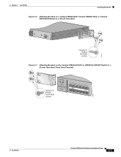
Chapter 2 Installation Installing the Switch Figure 2-6 Attaching Brackets on a Catalyst 2950G-48-EI, Catalyst 2950SX-48-SI, or Catalyst 2950T-48-SI Switch in a 19-Inch Telco Rack CONSOLE 65514 Number-8 Phillips flat-head screws Figure 2-7 Attaching Brackets on the Catalyst 2950G-24-EI-DC or 2950ST-24 LRE 997 Switch in a 23-Inch Telco Rack (Front Panel Forward) Number-8 Phillips truss-head screws SYST RPS STAT UTIL DUPLX SPEED MODE 1 1X 23 45 67 8 9 10 11 12 11X 2X 12X 65673 OL-6156-01 Catalyst 2950 Switch Hardware Installation Guide 2-11
Chapter 2 Installation Installing the Switch Figure 2-6 Attaching Brackets on a Catalyst 2950G-48-EI, Catalyst 2950SX-48-SI, or Catalyst 2950T-48-SI Switch in a 19-Inch Telco Rack CONSOLE 65514 Number-8 Phillips flat-head screws Figure 2-7 Attaching Brackets on the Catalyst 2950G-24-EI-DC or 2950ST-24 LRE 997 Switch in a 23-Inch Telco Rack (Front Panel Forward) Number-8 Phillips truss-head screws SYST RPS STAT UTIL DUPLX SPEED MODE 1 1X 23 45 67 8 9 10 11 12 11X 2X 12X 65673 OL-6156-01 Catalyst 2950 Switch Hardware Installation Guide 2-11
Hardware Installation Guide
Page 73
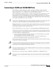
... two logical ports, each logical port, you can set the speed and duplex parameters. If the Catalyst 2950 LRE switch senses more information on Catalyst 2950T-24 switches operate at the speed setting of attached devices. Follow these steps to connect the switch to 10BASE-T, 100BASE-TX, or 1000BASE-T devices: Caution To prevent electrostatic-discharge (ESD) damage, follow...
... two logical ports, each logical port, you can set the speed and duplex parameters. If the Catalyst 2950 LRE switch senses more information on Catalyst 2950T-24 switches operate at the speed setting of attached devices. Follow these steps to connect the switch to 10BASE-T, 100BASE-TX, or 1000BASE-T devices: Caution To prevent electrostatic-discharge (ESD) damage, follow...
Hardware Installation Guide
Page 74
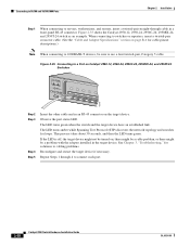
... cable in the target device. Observe the port status LED. The LED turns green when the switch and the target device have an established link. Figure 2-35 Connecting to a Port on Catalyst 2950-12, 2950-24, 2950C-24, 2950SX-24, and 2950T-24 Switches SYST RPS STAT UTIL DUPLX SPEED MODE 1x 2x 3x 4x 5x 45576 Step 2 Step 3 Step...
... cable in the target device. Observe the port status LED. The LED turns green when the switch and the target device have an established link. Figure 2-35 Connecting to a Port on Catalyst 2950-12, 2950-24, 2950C-24, 2950SX-24, and 2950T-24 Switches SYST RPS STAT UTIL DUPLX SPEED MODE 1x 2x 3x 4x 5x 45576 Step 2 Step 3 Step...

Hardware Installation Guide
Page 91
...and Table A-9 list the regulatory agency approvals for the Catalyst 2950G-24-EI-DC switch. Table A-1 Technical Specifications for Catalyst 2950-12, 2950-24, 2950C-24, 2950SX-24, and 2950T-24 Switches Environmental Ranges Operating temperature 32 to 113°F (0... x 9.52 in . Table A-6 lists the technical specifications for the switches other than the Catalyst 2950 Long-Reach Ethernet (LRE) switches. A A P P E N D I X Technical Specifications OL-6156-01 Table A-1 through Table A-5 list the technical specifications for the Cisco RPS 675 +12 V @4.5 A Power consumption 30 W (maximum) ...
...and Table A-9 list the regulatory agency approvals for the Catalyst 2950G-24-EI-DC switch. Table A-1 Technical Specifications for Catalyst 2950-12, 2950-24, 2950C-24, 2950SX-24, and 2950T-24 Switches Environmental Ranges Operating temperature 32 to 113°F (0... x 9.52 in . Table A-6 lists the technical specifications for the switches other than the Catalyst 2950 Long-Reach Ethernet (LRE) switches. A A P P E N D I X Technical Specifications OL-6156-01 Table A-1 through Table A-5 list the technical specifications for the Cisco RPS 675 +12 V @4.5 A Power consumption 30 W (maximum) ...
Hardware Installation Guide
Page 100
... Appendix B Connectors and Cables Note Use a straight-through cable to connect two ports only when one time. If the Catalyst 2950 LRE switch senses more information on Catalyst 2950T-24, Catalyst 2950T-48-SI, and Catalyst 2950 Long-Reach Ethernet (LRE) switches use Category 5 cabling when connecting to 10BASE-T- Use a crossover cable to connect two ports when both logical ports, the...
... Appendix B Connectors and Cables Note Use a straight-through cable to connect two ports only when one time. If the Catalyst 2950 LRE switch senses more information on Catalyst 2950T-24, Catalyst 2950T-48-SI, and Catalyst 2950 Long-Reach Ethernet (LRE) switches use Category 5 cabling when connecting to 10BASE-T- Use a crossover cable to connect two ports when both logical ports, the...

Hardware Installation Guide
Page 106
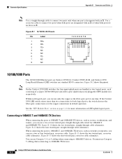
...- 65274 RJ-21 Cable Pinouts Table B-1 lists the RJ-21 cable pinouts on Catalyst 2950T-24 switches, Catalyst 2950 LRE switches, and 1000BASE-T GBIC module ports. Figure B-14 Four Twisted-Pair Straight-Through Cable Schematic for 10/100/1000 and 1000BASE-T GBIC Module Ports Switch 1 TPO+ 2 TPO3 TP1+ 6 TP1- Cable and Adapter Specifications Appendix B Connectors and Cables Four...
...- 65274 RJ-21 Cable Pinouts Table B-1 lists the RJ-21 cable pinouts on Catalyst 2950T-24 switches, Catalyst 2950 LRE switches, and 1000BASE-T GBIC module ports. Figure B-14 Four Twisted-Pair Straight-Through Cable Schematic for 10/100/1000 and 1000BASE-T GBIC Module Ports Switch 1 TPO+ 2 TPO3 TP1+ 6 TP1- Cable and Adapter Specifications Appendix B Connectors and Cables Four...
