Software Configuration Guide
Page 35
... 1-1 and in the release notes. Table 1-1 Switches Supported Switch Catalyst 2950-12 Catalyst 2950-24 Catalyst 2950C-24 Catalyst 2950G-12-EI Catalyst 2950G-24-EI Catalyst 2950G-24-EI-DC Catalyst 2950G-48-EI Catalyst 2950ST-8 LRE Catalyst 2950ST-24 LRE Catalyst 2950ST-24 LRE 997 Catalyst 2950SX-24 Catalyst 2950SX-48-SI Catalyst 2950T-24 Catalyst 2950T-48-SI Software Image SI1 SI EI2 EI EI EI EI EI EI EI SI SI EI SI 78-11380-10 Catalyst 2950 and Catalyst 2955 Switch Software Configuration Guide 1-1 Layer 3 IP...
... 1-1 and in the release notes. Table 1-1 Switches Supported Switch Catalyst 2950-12 Catalyst 2950-24 Catalyst 2950C-24 Catalyst 2950G-12-EI Catalyst 2950G-24-EI Catalyst 2950G-24-EI-DC Catalyst 2950G-48-EI Catalyst 2950ST-8 LRE Catalyst 2950ST-24 LRE Catalyst 2950ST-24 LRE 997 Catalyst 2950SX-24 Catalyst 2950SX-48-SI Catalyst 2950T-24 Catalyst 2950T-48-SI Software Image SI1 SI EI2 EI EI EI EI EI EI EI SI SI EI SI 78-11380-10 Catalyst 2950 and Catalyst 2955 Switch Software Configuration Guide 1-1 Layer 3 IP...
Software Configuration Guide
Page 37
... port (private VLAN edge port) option for restricting the forwarding of bandwidth between switches, routers, and servers • Support for the cluster hardware and software requirements, refer to designated ports on page 1-9. Catalyst 2950 LRE switches - Catalyst 2950G-12-EI, 2950G-24-EI, 2950G-24-EI-DC, and 2950G-48-EI switches running Cisco IOS Release 12.1(6)EA2 or later - Chapter 1 Overview Features 78-11380-10...
... port (private VLAN edge port) option for restricting the forwarding of bandwidth between switches, routers, and servers • Support for the cluster hardware and software requirements, refer to designated ports on page 1-9. Catalyst 2950 LRE switches - Catalyst 2950G-12-EI, 2950G-24-EI, 2950G-24-EI-DC, and 2950G-48-EI switches running Cisco IOS Release 12.1(6)EA2 or later - Chapter 1 Overview Features 78-11380-10...

Software Configuration Guide
Page 457
... with unknown destination MAC addresses to all ports in the port channel group. 78-11380-10 Catalyst 2950 and Catalyst 2955 Switch Software Configuration Guide 22-5 Verify your entries. (Optional) Save your entries in the configuration file...Configuring Port Blocking Beginning in privileged EXEC mode, follow these switches: • Catalyst 2950 Long-Reach Ethernet (LRE) switches running Cisco IOS Release 12.1(14)EA1 or later • Catalyst 2950G-12-EI, 2950G-24-EI, 2950G-24-EI-DC, 2950G-48-EI, and 2955 switches running -config startup-config Purpose Enter global configuration mode....
... with unknown destination MAC addresses to all ports in the port channel group. 78-11380-10 Catalyst 2950 and Catalyst 2955 Switch Software Configuration Guide 22-5 Verify your entries. (Optional) Save your entries in the configuration file...Configuring Port Blocking Beginning in privileged EXEC mode, follow these switches: • Catalyst 2950 Long-Reach Ethernet (LRE) switches running Cisco IOS Release 12.1(14)EA1 or later • Catalyst 2950G-12-EI, 2950G-24-EI, 2950G-24-EI-DC, 2950G-48-EI, and 2955 switches running -config startup-config Purpose Enter global configuration mode....

Hardware Installation Guide
Page 22
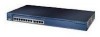
....) - Catalyst 2950T-48-SI switch-48 10/100 Ethernet ports and 2 10/100/1000 Ethernet ports - On Catalyst 2950G-12-EI, 2950G-24-EI, 2950G-24-EI-DC, and 2950G-48-EI switches, support for errors on a received packet, determines the destination port, stores the packet in shared memory, and then forwards the packet to the destination port Catalyst 2950 Switch Hardware Installation Guide 1-2 OL-6156-01 Catalyst 2950G-24-EI...
....) - Catalyst 2950T-48-SI switch-48 10/100 Ethernet ports and 2 10/100/1000 Ethernet ports - On Catalyst 2950G-12-EI, 2950G-24-EI, 2950G-24-EI-DC, and 2950G-48-EI switches, support for errors on a received packet, determines the destination port, stores the packet in shared memory, and then forwards the packet to the destination port Catalyst 2950 Switch Hardware Installation Guide 1-2 OL-6156-01 Catalyst 2950G-24-EI...
Hardware Installation Guide
Page 25
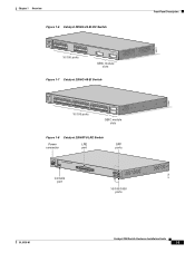
... 12 11X 2X 12X 13X 13 14 15 16 17 18 19 20 21 22 23 24 23X 14X 24X 10/100 ports 1 Catalyst 2950 SERIES 2 GBIC module slots Figure 1-7 Catalyst 2950G-48-EI Switch SYST RPS STAT UTIL DUPLX SPEED MODE 1 1X 2X 23 45 67 8 9 10 11 12 13 14 15 16 17 15X 17X... 18X 33 31X 33X 34 35 36 37 38 39 40 41 42 43 44 45 46 47 48 47X 32X 34X 48X 10/100 ports Catalyst 2950 SERIES 1 2 GBIC module slots Figure 1-8 Catalyst 2950ST-8 LRE Switch Power LRE connector port SFP ports 110.00A-1/02R.75A/TA2I0N500G--26400HVZ~ MODE SYST RPS STAT SPEED CONSOLE...
... 12 11X 2X 12X 13X 13 14 15 16 17 18 19 20 21 22 23 24 23X 14X 24X 10/100 ports 1 Catalyst 2950 SERIES 2 GBIC module slots Figure 1-7 Catalyst 2950G-48-EI Switch SYST RPS STAT UTIL DUPLX SPEED MODE 1 1X 2X 23 45 67 8 9 10 11 12 13 14 15 16 17 15X 17X... 18X 33 31X 33X 34 35 36 37 38 39 40 41 42 43 44 45 46 47 48 47X 32X 34X 48X 10/100 ports Catalyst 2950 SERIES 1 2 GBIC module slots Figure 1-8 Catalyst 2950ST-8 LRE Switch Power LRE connector port SFP ports 110.00A-1/02R.75A/TA2I0N500G--26400HVZ~ MODE SYST RPS STAT SPEED CONSOLE...

Hardware Installation Guide
Page 33
...: • Figure 1-15 for the Catalyst 2950-12, 2950-24, 2950C-24, 2950SX-24, and 2950T-24 switches • Figure 1-16 for the Catalyst 2950G-12-EI, 2950G-24-EI, and 2950G-24-EI-DC switches • Figure 1-17 for the Catalyst 2950G-48-EI, Catalyst 2950SX-48-SI, and Catalyst 2950T-48-SI switches • Figure 1-18 for the Catalyst 2950ST-8 LRE and 2950ST-24 LRE switches • Figure 1-19 for the...
...: • Figure 1-15 for the Catalyst 2950-12, 2950-24, 2950C-24, 2950SX-24, and 2950T-24 switches • Figure 1-16 for the Catalyst 2950G-12-EI, 2950G-24-EI, and 2950G-24-EI-DC switches • Figure 1-17 for the Catalyst 2950G-48-EI, Catalyst 2950SX-48-SI, and Catalyst 2950T-48-SI switches • Figure 1-18 for the Catalyst 2950ST-8 LRE and 2950ST-24 LRE switches • Figure 1-19 for the...
Hardware Installation Guide
Page 34
... RPS STAT UTIL DUPLX SPEED MODE 1 1X 23 45 67 8 9 10 11 12 11X 2X 12X Mode button Figure 1-17 LEDs on Catalyst 2950G-48-EI, 2950SX-48-SI, and 2950T-48-SI Switches Port status LEDs System LED RPS LED Port mode LEDs SYST RPS STAT UTIL DUPLX SPEED MODE 1 1X 23 45 67 89 10...
... RPS STAT UTIL DUPLX SPEED MODE 1 1X 23 45 67 8 9 10 11 12 11X 2X 12X Mode button Figure 1-17 LEDs on Catalyst 2950G-48-EI, 2950SX-48-SI, and 2950T-48-SI Switches Port status LEDs System LED RPS LED Port mode LEDs SYST RPS STAT UTIL DUPLX SPEED MODE 1 1X 23 45 67 89 10...
Hardware Installation Guide
Page 40
... 23 24 1X SYST RPS 11X 13X 15X 1 STAT UTIL DUPLX SPEED 2X 12X 14X 16X MODE < 25% + 25% - 49% + 50% + Catalyst 2950 2 If all LEDs on a Catalyst 2950G-48-EI, 2950SX-48-SI, or 2950T-48-SI switch are green, the switch is using less than 25 percent of the total bandwidth, and so on. (See Figure 1-24.) 1-20...
... 23 24 1X SYST RPS 11X 13X 15X 1 STAT UTIL DUPLX SPEED 2X 12X 14X 16X MODE < 25% + 25% - 49% + 50% + Catalyst 2950 2 If all LEDs on a Catalyst 2950G-48-EI, 2950SX-48-SI, or 2950T-48-SI switch are green, the switch is using less than 25 percent of the total bandwidth, and so on. (See Figure 1-24.) 1-20...

Hardware Installation Guide
Page 41
... only an RPS connector. (See Figure 1-28.) Figure 1-25 Catalyst 2950 Switch Rear Panel 45585 12005R@[email protected]~~ AC power connector [email protected]. CONSOLE RPS connector Fan RJ-45 console port Figure 1-26 Catalyst 2950G-48-EI, Catalyst 2950SX-48-SI, and Catalyst 2950T-48-SI Switch Rear Panel 65511 12005R@[email protected]~~ AC power connector DSCPEIPNC+OPI1FWU2IETVEDRFOIS...
... only an RPS connector. (See Figure 1-28.) Figure 1-25 Catalyst 2950 Switch Rear Panel 45585 12005R@[email protected]~~ AC power connector [email protected]. CONSOLE RPS connector Fan RJ-45 console port Figure 1-26 Catalyst 2950G-48-EI, Catalyst 2950SX-48-SI, and Catalyst 2950T-48-SI Switch Rear Panel 65511 12005R@[email protected]~~ AC power connector DSCPEIPNC+OPI1FWU2IETVEDRFOIS...

Hardware Installation Guide
Page 43
... to connect the RPS to the switch. It automatically senses when the internal power supply of 675 W. Cisco RPS 675 The Cisco RPS 675 has two output levels: -48 V and 12 V with a total maximum output power of network traffic. OL-6156-01 Catalyst 2950 Switch Hardware Installation Guide 1-23 Statement 100B...-AC-RPS-N1) to the RPS receptacle. Warning Attach only the Cisco RPS 675 (model PWR675-AC-RPS-N1=) to the RPS receptacle. Caution You must connect the Catalyst 2950G-24-EI-DC and 2950ST-24 LRE 997 switches only to one failed device at a time. It automatically senses when...
... to connect the RPS to the switch. It automatically senses when the internal power supply of 675 W. Cisco RPS 675 The Cisco RPS 675 has two output levels: -48 V and 12 V with a total maximum output power of network traffic. OL-6156-01 Catalyst 2950 Switch Hardware Installation Guide 1-23 Statement 100B...-AC-RPS-N1) to the RPS receptacle. Warning Attach only the Cisco RPS 675 (model PWR675-AC-RPS-N1=) to the RPS receptacle. Caution You must connect the Catalyst 2950G-24-EI-DC and 2950ST-24 LRE 997 switches only to one failed device at a time. It automatically senses when...

Hardware Installation Guide
Page 49
... Avoid direct exposure to the terminals. Statement 121D OL-6156-01 Catalyst 2950 Switch Hardware Installation Guide 2-3 Metal objects will heat up . Statement 266 Warning If an RPS is not connected to the switch, install an RPS connector cover on equipment that the host is...the laser beam. Chapter 2 Installation Preparing for this unit, contact your reseller or Cisco sales representative. Statement 48 Warning To comply with optical instruments. Statement 1051 Warning The Catalyst 2950G-24-EI-DC contains no field-replaceable units (FRUs). Do not open the chassis or ...
... Avoid direct exposure to the terminals. Statement 121D OL-6156-01 Catalyst 2950 Switch Hardware Installation Guide 2-3 Metal objects will heat up . Statement 266 Warning If an RPS is not connected to the switch, install an RPS connector cover on equipment that the host is...the laser beam. Chapter 2 Installation Preparing for this unit, contact your reseller or Cisco sales representative. Statement 48 Warning To comply with optical instruments. Statement 1051 Warning The Catalyst 2950G-24-EI-DC contains no field-replaceable units (FRUs). Do not open the chassis or ...
Hardware Installation Guide
Page 53
... Catalyst 2950 Switches, page 2-19 Installing the Switch in a Rack Use these instructions to install the switch in a rack: Warning To prevent bodily injury when mounting or servicing this unit in a partially filled rack, load the rack from Cisco (part number RCKMNT-1RU=). Attaching the Optional Cable Guide, page 2-16 Note Installing a Catalyst 2950G-48-EI, Catalyst 2950SX-48-SI, or Catalyst 2950T-48...
... Catalyst 2950 Switches, page 2-19 Installing the Switch in a Rack Use these instructions to install the switch in a rack: Warning To prevent bodily injury when mounting or servicing this unit in a partially filled rack, load the rack from Cisco (part number RCKMNT-1RU=). Attaching the Optional Cable Guide, page 2-16 Note Installing a Catalyst 2950G-48-EI, Catalyst 2950SX-48-SI, or Catalyst 2950T-48...
Hardware Installation Guide
Page 54
... screws SYST RPS STAT UTIL DUPLX SPEED MODE 1x 2x 3x 4x 5x Catalyst 2950 Switch Hardware Installation Guide 2-8 OL-6156-01 or 24-inch bracket to the switch. See Figure 2-1, Figure 2-2, and Figure 2-3. • When mounting a Catalyst 2950G-48-EI, Catalyst 2950SX-48-SI, or Catalyst 2950T-48-SI switch in a 19-inch rack, use three Phillips flat-head screws to attach...
... screws SYST RPS STAT UTIL DUPLX SPEED MODE 1x 2x 3x 4x 5x Catalyst 2950 Switch Hardware Installation Guide 2-8 OL-6156-01 or 24-inch bracket to the switch. See Figure 2-1, Figure 2-2, and Figure 2-3. • When mounting a Catalyst 2950G-48-EI, Catalyst 2950SX-48-SI, or Catalyst 2950T-48-SI switch in a 19-inch rack, use three Phillips flat-head screws to attach...
Hardware Installation Guide
Page 56
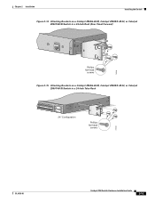
... UTIL DUPLX SPEED MODE 1 1X 23 45 67 89 10 11 12 13 14 15 16 15X 2X 16X 65512 Figure 2-5 Attaching Brackets on a Catalyst 2950G-48-EI, Catalyst 2950SX-48-SI, or Catalyst 2950T-48-SI Switch in a 19-Inch Rack (Rear Panel Forward) CONSOLE Number-8 Phillips flat-head screws 65513 2-10 Catalyst 2950 Switch Hardware Installation Guide OL-6156-01
... UTIL DUPLX SPEED MODE 1 1X 23 45 67 89 10 11 12 13 14 15 16 15X 2X 16X 65512 Figure 2-5 Attaching Brackets on a Catalyst 2950G-48-EI, Catalyst 2950SX-48-SI, or Catalyst 2950T-48-SI Switch in a 19-Inch Rack (Rear Panel Forward) CONSOLE Number-8 Phillips flat-head screws 65513 2-10 Catalyst 2950 Switch Hardware Installation Guide OL-6156-01
Hardware Installation Guide
Page 57
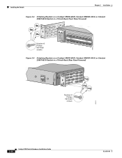
Chapter 2 Installation Installing the Switch Figure 2-6 Attaching Brackets on a Catalyst 2950G-48-EI, Catalyst 2950SX-48-SI, or Catalyst 2950T-48-SI Switch in a 19-Inch Telco Rack CONSOLE 65514 Number-8 Phillips flat-head screws Figure 2-7 Attaching Brackets on the Catalyst 2950G-24-EI-DC or 2950ST-24 LRE 997 Switch in a 23-Inch Telco Rack (Front Panel Forward) Number-8 Phillips truss-head screws SYST RPS STAT UTIL DUPLX SPEED MODE 1 1X 23 45 67 8 9 10 11 12 11X 2X 12X 65673 OL-6156-01 Catalyst 2950 Switch Hardware Installation Guide 2-11
Chapter 2 Installation Installing the Switch Figure 2-6 Attaching Brackets on a Catalyst 2950G-48-EI, Catalyst 2950SX-48-SI, or Catalyst 2950T-48-SI Switch in a 19-Inch Telco Rack CONSOLE 65514 Number-8 Phillips flat-head screws Figure 2-7 Attaching Brackets on the Catalyst 2950G-24-EI-DC or 2950ST-24 LRE 997 Switch in a 23-Inch Telco Rack (Front Panel Forward) Number-8 Phillips truss-head screws SYST RPS STAT UTIL DUPLX SPEED MODE 1 1X 23 45 67 8 9 10 11 12 11X 2X 12X 65673 OL-6156-01 Catalyst 2950 Switch Hardware Installation Guide 2-11
Hardware Installation Guide
Page 60
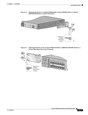
Installing the Switch Figure 2-12 Attaching Brackets on the Switch in a 24-Inch Telco Rack Chapter 2 Installation CONSOLE 65667 Number-8 Phillips truss-head screws Figure 2-13 Attaching Brackets on a Catalyst 2950G-48-EI, Catalyst 2950SX-48-SI, or Catalyst 2950T-48-SI Switch in a 24-Inch Rack (Front Panel Forward) Phillips flat-head screws SYST RPS STAT UTIL DUPLX SPEED MODE 1 1X 23 45 67 8 9 10 11 12 13 14 15 16 15X 2X 16X 74528 2-14 Catalyst 2950 Switch Hardware Installation Guide OL-6156-01
Installing the Switch Figure 2-12 Attaching Brackets on the Switch in a 24-Inch Telco Rack Chapter 2 Installation CONSOLE 65667 Number-8 Phillips truss-head screws Figure 2-13 Attaching Brackets on a Catalyst 2950G-48-EI, Catalyst 2950SX-48-SI, or Catalyst 2950T-48-SI Switch in a 24-Inch Rack (Front Panel Forward) Phillips flat-head screws SYST RPS STAT UTIL DUPLX SPEED MODE 1 1X 23 45 67 8 9 10 11 12 13 14 15 16 15X 2X 16X 74528 2-14 Catalyst 2950 Switch Hardware Installation Guide OL-6156-01
Hardware Installation Guide
Page 61
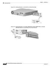
Chapter 2 Installation Installing the Switch Figure 2-14 Attaching Brackets on a Catalyst 2950G-48-EI, Catalyst 2950SX-48-SI, or Catalyst 2950T-48-SI Switch in a 24-Inch Rack (Rear Panel Forward) CONSOLE 74529 Phillips flat-head screws Figure 2-15 Attaching Brackets on a Catalyst 2950G-48-EI, Catalyst 2950SX-48-SI, or Catalyst 2950T-48-SI Switch in a 24-Inch Telco Rack 33 34 35 36 37 38 39 40 41 42 43 44 45 46 47 48 47X 48X Catalyst 2950 SERIES 1 2 24" Configuration Phillips flat-head screws 74530 OL-6156-01 Catalyst 2950 Switch Hardware Installation Guide 2-15
Chapter 2 Installation Installing the Switch Figure 2-14 Attaching Brackets on a Catalyst 2950G-48-EI, Catalyst 2950SX-48-SI, or Catalyst 2950T-48-SI Switch in a 24-Inch Rack (Rear Panel Forward) CONSOLE 74529 Phillips flat-head screws Figure 2-15 Attaching Brackets on a Catalyst 2950G-48-EI, Catalyst 2950SX-48-SI, or Catalyst 2950T-48-SI Switch in a 24-Inch Telco Rack 33 34 35 36 37 38 39 40 41 42 43 44 45 46 47 48 47X 48X Catalyst 2950 SERIES 1 2 24" Configuration Phillips flat-head screws 74530 OL-6156-01 Catalyst 2950 Switch Hardware Installation Guide 2-15
Hardware Installation Guide
Page 73
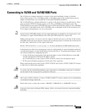
... respectively. Within each consisting of attached devices.They operate at 10 or 100 Mbps in half- Caution The Catalyst 2950G-24-EI-DC or Catalyst 2950ST-24 LRE 997 switch is suitable only for both ends of these methods for more than two connections for intrabuilding or nonexposed wiring ...and duplex parameters can use only the copper or the fiber-optic port at both ends. If the Catalyst 2950 LRE switch senses more information on Catalyst 2950 LRE and Catalyst 2950T-48-SI switches operate at 1000 Mbps only in full-duplex mode. The 10/100/1000 ports on LRE uplink logical...
... respectively. Within each consisting of attached devices.They operate at 10 or 100 Mbps in half- Caution The Catalyst 2950G-24-EI-DC or Catalyst 2950ST-24 LRE 997 switch is suitable only for both ends of these methods for more than two connections for intrabuilding or nonexposed wiring ...and duplex parameters can use only the copper or the fiber-optic port at both ends. If the Catalyst 2950 LRE switch senses more information on Catalyst 2950 LRE and Catalyst 2950T-48-SI switches operate at 1000 Mbps only in full-duplex mode. The 10/100/1000 ports on LRE uplink logical...
Hardware Installation Guide
Page 92
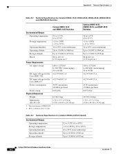
...Cisco RPS 675 Power consumption 30 W (maximum) 102 Btus per sec)1 AC input voltage 100 to 127/200 to 240 VAC (autoranging) 50 to 15,000 ft (4570 m) Catalyst 2950 Switch Hardware Installation Guide A-2 OL-6156-01 RPS = redundant power system Catalyst 2950G-48-EI, 2950SX-48-SI, and 2950T-48-SI Switches... 60 Hz DC input voltage for the +12 V @4.5 A Cisco RPS2 300 DC input voltage for Catalyst 2950G-12-EI, 2950G-24-EI, 2950G-48-EI, 2950SX-48-SI, and 2950T-48-SI Switches Catalyst 2950G-12-EI and 2950G-24-EI Switches Environmental Ranges Operating temperature 32 to 113°F (0 to 45...
...Cisco RPS 675 Power consumption 30 W (maximum) 102 Btus per sec)1 AC input voltage 100 to 127/200 to 240 VAC (autoranging) 50 to 15,000 ft (4570 m) Catalyst 2950 Switch Hardware Installation Guide A-2 OL-6156-01 RPS = redundant power system Catalyst 2950G-48-EI, 2950SX-48-SI, and 2950T-48-SI Switches... 60 Hz DC input voltage for the +12 V @4.5 A Cisco RPS2 300 DC input voltage for Catalyst 2950G-12-EI, 2950G-24-EI, 2950G-48-EI, 2950SX-48-SI, and 2950T-48-SI Switches Catalyst 2950G-12-EI and 2950G-24-EI Switches Environmental Ranges Operating temperature 32 to 113°F (0 to 45...
