
Hardware Installation Guide
Page 4
...23 Cisco RPS Connector 1-23 Console Port 1-24 Management Options 1-24 Installation 2-1 Preparing for Installation 2-1 Warnings 2-1 Installation Guidelines 2-4 Verifying Package Contents 2-5 Verifying Switch Operation 2-6 Installing the Switch 2-7 Installing the Switch in a Rack 2-7 Attaching the Brackets to the Switch 2-8 Mounting the Switch ...Switch on a Table, Shelf, or Desk 2-17 Installing the Switch on a Wall 2-17 Attaching the Brackets to the Switch 2-17 Attaching the RPS Connector Cover 2-18 Mounting the Switch to a Wall 2-18 Installing the Optional AC Ground Kit for Catalyst 2950 Switches...
...23 Cisco RPS Connector 1-23 Console Port 1-24 Management Options 1-24 Installation 2-1 Preparing for Installation 2-1 Warnings 2-1 Installation Guidelines 2-4 Verifying Package Contents 2-5 Verifying Switch Operation 2-6 Installing the Switch 2-7 Installing the Switch in a Rack 2-7 Attaching the Brackets to the Switch 2-8 Mounting the Switch ...Switch on a Table, Shelf, or Desk 2-17 Installing the Switch on a Wall 2-17 Attaching the Brackets to the Switch 2-17 Attaching the RPS Connector Cover 2-18 Mounting the Switch to a Wall 2-18 Installing the Optional AC Ground Kit for Catalyst 2950 Switches...
Hardware Installation Guide
Page 18
...operations running smoothly. Cisco.com features the Cisco TAC website as an online starting point for an immediate solution. xviii Catalyst 2950 Switch Hardware Installation Guide OL-6156-01 Obtaining Technical Assistance For all the tools on Cisco.com. The Cisco TAC website is ...recommends resources for technical assistance. Accessing all customers, partners, resellers, and distributors who hold valid Cisco service contracts, the Cisco Technical Assistance Center (TAC) provides 24-hour, award-winning technical support services, online and over the phone. If you have a valid...
...operations running smoothly. Cisco.com features the Cisco TAC website as an online starting point for an immediate solution. xviii Catalyst 2950 Switch Hardware Installation Guide OL-6156-01 Obtaining Technical Assistance For all the tools on Cisco.com. The Cisco TAC website is ...recommends resources for technical assistance. Accessing all customers, partners, resellers, and distributors who hold valid Cisco service contracts, the Cisco Technical Assistance Center (TAC) provides 24-hour, award-winning technical support services, online and over the phone. If you have a valid...

Hardware Installation Guide
Page 23
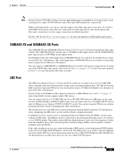
... 11x 10Base-T / 100Base-TX 12x 10/100 ports Catalyst 2950 SERIES OL-6156-01 Catalyst 2950 Switch Hardware Installation Guide 1-3 Table 1-1 LRE Switch and CPE Compatibility Matrix LRE Devices Catalyst 2950ST-8 LRE Cisco 575 LRE Yes CPE Cisco 576 LRE 997 No CPE Cisco 585 LRE Yes CPE Catalyst 2950ST-24 LRE Catalyst 2950ST-24 LRE 997 Yes No No Yes Yes No Front...
... 11x 10Base-T / 100Base-TX 12x 10/100 ports Catalyst 2950 SERIES OL-6156-01 Catalyst 2950 Switch Hardware Installation Guide 1-3 Table 1-1 LRE Switch and CPE Compatibility Matrix LRE Devices Catalyst 2950ST-8 LRE Cisco 575 LRE Yes CPE Cisco 576 LRE 997 No CPE Cisco 585 LRE Yes CPE Catalyst 2950ST-24 LRE Catalyst 2950ST-24 LRE 997 Yes No No Yes Yes No Front...
Hardware Installation Guide
Page 29
...-optic connections over distances of up to 24 Cisco LRE CPE devices through a plain old telephone service (POTS) splitter. The default mode for the Cisco LRE 48 POTS Splitter. Chapter 1 Overview Front-Panel Description Note On the Catalyst 2950 LRE switches, the four input uplink ports are connected through a PBX switch, a non-homologated POTS splitter, such as...
...-optic connections over distances of up to 24 Cisco LRE CPE devices through a plain old telephone service (POTS) splitter. The default mode for the Cisco LRE 48 POTS Splitter. Chapter 1 Overview Front-Panel Description Note On the Catalyst 2950 LRE switches, the four input uplink ports are connected through a PBX switch, a non-homologated POTS splitter, such as...

Hardware Installation Guide
Page 42
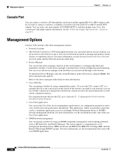
...-8 LRE Switch, Catalyst 2950ST-24 LRE, and Catalyst 2950ST-24 LRE 997 Switch Rear Panel RPS Fans connector 81225 Power Connectors You can order these L-shaped AC power cords from your Cisco sales representative: • CAB-NP1200-AC-AR= • CAB-NP1200-AC-AU= • CAB-NP1200-AC-CH= • CAB-NP1200-AC-EU= 1-22 Catalyst 2950 Switch Hardware Installation...
...-8 LRE Switch, Catalyst 2950ST-24 LRE, and Catalyst 2950ST-24 LRE 997 Switch Rear Panel RPS Fans connector 81225 Power Connectors You can order these L-shaped AC power cords from your Cisco sales representative: • CAB-NP1200-AC-AR= • CAB-NP1200-AC-AU= • CAB-NP1200-AC-CH= • CAB-NP1200-AC-EU= 1-22 Catalyst 2950 Switch Hardware Installation...

Hardware Installation Guide
Page 43
...Catalyst 2950 Switch Hardware Installation Guide 1-23 Chapter 1 Overview Rear-Panel Description • CAB-NP1200-AC-IT= • CAB-NP1200-AC-JP= • CAB-NP1200-AC-UK= • CAB-NP1200-AC-US= DC Power Connector The Catalyst 2950G-24-EI-DC and Catalyst 2950ST-24 LRE 997 switches have an internal DC-power converter. Cisco... RPS 675 The Cisco RPS 675 has two output levels: -48 V and 12 V with a total ...
...Catalyst 2950 Switch Hardware Installation Guide 1-23 Chapter 1 Overview Rear-Panel Description • CAB-NP1200-AC-IT= • CAB-NP1200-AC-JP= • CAB-NP1200-AC-UK= • CAB-NP1200-AC-US= DC Power Connector The Catalyst 2950G-24-EI-DC and Catalyst 2950ST-24 LRE 997 switches have an internal DC-power converter. Cisco... RPS 675 The Cisco RPS 675 has two output levels: -48 V and 12 V with a total ...
Hardware Installation Guide
Page 44
...as HP OpenView and SunNet Manager. Refer to perform basic switch configuration and monitoring. For more information, see the "Cable and Adapter Specifications" section on your SNMP application. 1-24 Catalyst 2950 Switch Hardware Installation Guide OL-6156-01 Use the device manager ...to the device manager online help . • Device Manager You can use Network Assistant to run on page B-6. For setup instructions that adapter from a remote location. For more information. • Cisco...
...as HP OpenView and SunNet Manager. Refer to perform basic switch configuration and monitoring. For more information, see the "Cable and Adapter Specifications" section on your SNMP application. 1-24 Catalyst 2950 Switch Hardware Installation Guide OL-6156-01 Use the device manager ...to the device manager online help . • Device Manager You can use Network Assistant to run on page B-6. For setup instructions that adapter from a remote location. For more information. • Cisco...

Hardware Installation Guide
Page 49
... equipment is intended to install, replace, or service this equipment. For information about obtaining service for this unit, contact your reseller or Cisco sales representative. Statement 121C Warning The Catalyst 2950ST-24 LRE 997 contains no field-replaceable units (FRUs). Statement 43 Warning Do not stack the chassis on the back of the... Class 1 laser product. If the chassis falls, it can cause serious burns or weld the metal object to the terminals. Statement 121D OL-6156-01 Catalyst 2950 Switch Hardware Installation Guide 2-3
... equipment is intended to install, replace, or service this equipment. For information about obtaining service for this unit, contact your reseller or Cisco sales representative. Statement 121C Warning The Catalyst 2950ST-24 LRE 997 contains no field-replaceable units (FRUs). Statement 43 Warning Do not stack the chassis on the back of the... Class 1 laser product. If the chassis falls, it can cause serious burns or weld the metal object to the terminals. Statement 121D OL-6156-01 Catalyst 2950 Switch Hardware Installation Guide 2-3

Hardware Installation Guide
Page 52
...verifies that the switch functions properly. Two 23-inch rack-mounting brackets (with the Catalyst 2950G-24-EI-DC or Catalyst 2950ST-24 LRE 997 switch. • ... to the switch - One DC terminal block plug (also called a terminal block header) - Call Cisco Systems if your switch does not ...switch. Verifying Switch Operation Before installing the switch in the getting started guide for attaching the ground lug to the switch - POST has completed successfully when the SYST and STAT LEDs are usually fatal. Catalyst 2950 Switch Hardware Installation Guide 2-6 OL-6156-01 If a switch...
...verifies that the switch functions properly. Two 23-inch rack-mounting brackets (with the Catalyst 2950G-24-EI-DC or Catalyst 2950ST-24 LRE 997 switch. • ... to the switch - One DC terminal block plug (also called a terminal block header) - Call Cisco Systems if your switch does not ...switch. Verifying Switch Operation Before installing the switch in the getting started guide for attaching the ground lug to the switch - POST has completed successfully when the SYST and STAT LEDs are usually fatal. Catalyst 2950 Switch Hardware Installation Guide 2-6 OL-6156-01 If a switch...
Hardware Installation Guide
Page 53
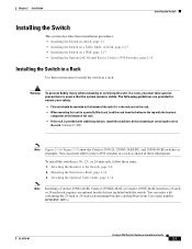
... the rack from Cisco (part number RCKMNT-1RU=). You can order a kit containing the 23-inch or 24-inch rack-mounting brackets and hardware from the bottom to ensure that the system remains stable. Attaching the Brackets to Figure 2-15 show the Catalyst 2950-24, 2950G-24-EI-DC, and 2950G-48-EI switches as shown in...
... the rack from Cisco (part number RCKMNT-1RU=). You can order a kit containing the 23-inch or 24-inch rack-mounting brackets and hardware from the bottom to ensure that the system remains stable. Attaching the Brackets to Figure 2-15 show the Catalyst 2950-24, 2950G-24-EI-DC, and 2950G-48-EI switches as shown in...
Hardware Installation Guide
Page 76
... and searches for the Cisco LRE 48 POTS Splitter. Connecting to the switch and private branch exchange (PBX) switch or public switched telephone network (PSTN). Note You can connect the LRE port to up to 8 or up to 24 LRE customer premises equipment (CPE) devices through 5 to the patch panel. 2-30 Catalyst 2950 Switch Hardware Installation Guide OL...
... and searches for the Cisco LRE 48 POTS Splitter. Connecting to the switch and private branch exchange (PBX) switch or public switched telephone network (PSTN). Note You can connect the LRE port to up to 8 or up to 24 LRE customer premises equipment (CPE) devices through 5 to the patch panel. 2-30 Catalyst 2950 Switch Hardware Installation Guide OL...
Hardware Installation Guide
Page 77
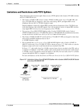
... analog and ISDN telephones that use the 0 to 120 kHz frequency range. • We recommend that you use a POTS splitter with Catalyst 2950 LRE switches and Cisco LRE CPE devices: • The Catalyst 2950ST-8 LRE switch, Catalyst 2950ST-24 LRE switch, Cisco 575 LRE CPE, and Cisco 585 LRE CPE are designed to share lines with analog, ISDN, and digital PBX...
... analog and ISDN telephones that use the 0 to 120 kHz frequency range. • We recommend that you use a POTS splitter with Catalyst 2950 LRE switches and Cisco LRE CPE devices: • The Catalyst 2950ST-8 LRE switch, Catalyst 2950ST-24 LRE switch, Cisco 575 LRE CPE, and Cisco 585 LRE CPE are designed to share lines with analog, ISDN, and digital PBX...

Hardware Installation Guide
Page 91
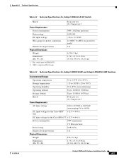
... Cisco RPS2 300 Redundant Power System 100 to 127/200 to 240 VAC (autoranging) 50 to 15,000 ft (4570 m) 84 in . (4.36 x 44.45 x 24.18 cm) 1. A A P P E N D I X Technical Specifications OL-6156-01 Table A-1 through Table A-5 list the technical specifications for fiber-optic uplink ports. Table A-6 lists the technical specifications for the Catalyst 2950 switches...
... Cisco RPS2 300 Redundant Power System 100 to 127/200 to 240 VAC (autoranging) 50 to 15,000 ft (4570 m) 84 in . (4.36 x 44.45 x 24.18 cm) 1. A A P P E N D I X Technical Specifications OL-6156-01 Table A-1 through Table A-5 list the technical specifications for fiber-optic uplink ports. Table A-6 lists the technical specifications for the Catalyst 2950 switches...
Hardware Installation Guide
Page 92
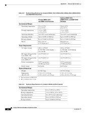
... to 127/200 to 240 VAC (autoranging) 50 to 15,000 ft (4570 m) Catalyst 2950 Switch Hardware Installation Guide A-2 OL-6156-01 RPS = redundant power system Catalyst 2950G-48-EI, 2950SX-48-SI, and 2950T-48-SI Switches 32 to 113°F (0 to 45°C) -13 to 158°F (-25 to...Cisco RPS 675 Power consumption 30 W (maximum) 102 Btus per hour 0.075 kVA 10.5 lb (4.8 kg) 1.72 x 17.5 x 13 in. (4.36 x 44.45 x 33.02 cm) Table A-3 Technical Specifications for Catalyst 2950G-12-EI, 2950G-24-EI, 2950G-48-EI, 2950SX-48-SI, and 2950T-48-SI Switches Catalyst 2950G-12-EI and 2950G-24-EI Switches...
... to 127/200 to 240 VAC (autoranging) 50 to 15,000 ft (4570 m) Catalyst 2950 Switch Hardware Installation Guide A-2 OL-6156-01 RPS = redundant power system Catalyst 2950G-48-EI, 2950SX-48-SI, and 2950T-48-SI Switches 32 to 113°F (0 to 45°C) -13 to 158°F (-25 to...Cisco RPS 675 Power consumption 30 W (maximum) 102 Btus per hour 0.075 kVA 10.5 lb (4.8 kg) 1.72 x 17.5 x 13 in. (4.36 x 44.45 x 33.02 cm) Table A-3 Technical Specifications for Catalyst 2950G-12-EI, 2950G-24-EI, 2950G-48-EI, 2950SX-48-SI, and 2950T-48-SI Switches Catalyst 2950G-12-EI and 2950G-24-EI Switches...
Hardware Installation Guide
Page 93
... (3.6 kg) Dimensions (H x W x D) 1.73 x 17.5 x 9.96 in . AWG = American Wire Gauge 84 in . (4.36 x 44.45 x 24.18 cm) Catalyst 2950 Switch Hardware Installation Guide A-3 per sec (2.13 m per sec)1 Power Requirements AC input voltage DC input voltage for the Cisco RPS2 300 100 to 127/200 to 240 VAC (autoranging) 50 to 60 Hz +12...
... (3.6 kg) Dimensions (H x W x D) 1.73 x 17.5 x 9.96 in . AWG = American Wire Gauge 84 in . (4.36 x 44.45 x 24.18 cm) Catalyst 2950 Switch Hardware Installation Guide A-3 per sec (2.13 m per sec)1 Power Requirements AC input voltage DC input voltage for the Cisco RPS2 300 100 to 127/200 to 240 VAC (autoranging) 50 to 60 Hz +12...

Hardware Installation Guide
Page 133
...25 removing 3-25 to 3-26 SFP ports, illustrated 2-5 shelf-mounting 3-17 SNMP network management platforms 2-24 software switch management 2-24 specifications A-1 to A-7 speed LED 2-17 to 2-19 status LED 2-17, 2-18 straight-through ...2-24 temperature operating A-1 to A-4 terminal-emulation software D-4 troubleshooting diagnosing problems 4-1 to 4-3 understanding POST results 4-1 OL-6156-01 Index U uplink ports, LRE 2-9 URLs, Cisco xvii utilization bandwidth 2-17 to 2-21 LED 2-17 V verifying package contents 3-5 to 3-6 W warnings DC power C-1 to C-4 installation 3-1 to 3-4 Catalyst 2950 Switch ...
...25 removing 3-25 to 3-26 SFP ports, illustrated 2-5 shelf-mounting 3-17 SNMP network management platforms 2-24 software switch management 2-24 specifications A-1 to A-7 speed LED 2-17 to 2-19 status LED 2-17, 2-18 straight-through ...2-24 temperature operating A-1 to A-4 terminal-emulation software D-4 troubleshooting diagnosing problems 4-1 to 4-3 understanding POST results 4-1 OL-6156-01 Index U uplink ports, LRE 2-9 URLs, Cisco xvii utilization bandwidth 2-17 to 2-21 LED 2-17 V verifying package contents 3-5 to 3-6 W warnings DC power C-1 to C-4 installation 3-1 to 3-4 Catalyst 2950 Switch ...

Configuration Guide
Page 62
...device could not join the cluster. Available only from the cluster. Not available in read -only mode. Available from a cluster member switch but not from the command switch. 2-24 Catalyst 2950 Desktop Switch Software Configuration Guide 78-11380-03 Not available in read -only mode. Launch Device Manager for...the total bandwidth in CMS" section on page 2-31. 2. For more information about the device and port on Cisco access points, but not from a cluster member switch but not on Cisco IP phones, hubs, routers and on either end of the link and the state of the link. 1. ...
...device could not join the cluster. Available only from the cluster. Not available in read -only mode. Available from a cluster member switch but not from the command switch. 2-24 Catalyst 2950 Desktop Switch Software Configuration Guide 78-11380-03 Not available in read -only mode. Launch Device Manager for...the total bandwidth in CMS" section on page 2-31. 2. For more information about the device and port on Cisco access points, but not from a cluster member switch but not on Cisco IP phones, hubs, routers and on either end of the link and the state of the link. 1. ...

Configuration Guide
Page 142
...more information, refer to the network. You can add a Cisco switch containing a RADIUS client to the RADIUS server documentation. RADIUS clients run on supported Cisco routers and switches (including Catalyst 3550 multilayer switches and Catalyst 2950 switches) and send authentication requests to be the first step when you...to a single host, to a single utility such as Telnet, or to meet special security and billing needs. 6-24 Catalyst 2950 Desktop Switch Software Configuration Guide 78-11380-03 An Internet service provider might be sent at the start and end of services, showing...
...more information, refer to the network. You can add a Cisco switch containing a RADIUS client to the RADIUS server documentation. RADIUS clients run on supported Cisco routers and switches (including Catalyst 3550 multilayer switches and Catalyst 2950 switches) and send authentication requests to be the first step when you...to a single host, to a single utility such as Telnet, or to meet special security and billing needs. 6-24 Catalyst 2950 Desktop Switch Software Configuration Guide 78-11380-03 An Internet service provider might be sent at the start and end of services, showing...
Configuration Guide
Page 172
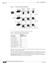
... Cisco router Catalyst 3500 series XL Engineering VLAN Marketing VLAN Accounting VLAN Fast Ethernet Catalyst 2900 series XL Catalyst 2950 series Floor 3 Floor 2 Floor 1 44961 Table 8-1 lists the number of Supported VLANs Catalyst 2950-12 64 Catalyst 2950-24 64 Catalyst 2950C-24 250 Catalyst 2950G-12-EI 250 Catalyst 2950G-24-EI 250 Catalyst 2950G-48-EI 250 Catalyst 2950G-24-EI-DC 250 Catalyst 2950T-24 250 The Catalyst 2950 switches...
... Cisco router Catalyst 3500 series XL Engineering VLAN Marketing VLAN Accounting VLAN Fast Ethernet Catalyst 2900 series XL Catalyst 2950 series Floor 3 Floor 2 Floor 1 44961 Table 8-1 lists the number of Supported VLANs Catalyst 2950-12 64 Catalyst 2950-24 64 Catalyst 2950C-24 250 Catalyst 2950G-12-EI 250 Catalyst 2950G-24-EI 250 Catalyst 2950G-48-EI 250 Catalyst 2950G-24-EI-DC 250 Catalyst 2950T-24 250 The Catalyst 2950 switches...

Configuration Guide
Page 230
...same priority value, STP puts the interface with the lowest interface number in the configuration file. Otherwise, you want selected last. Cisco IOS uses the port priority value when the interface is configured as an access port and uses VLAN port priority values when ... startup-config Purpose Enter global configuration mode. You can use the no spanning-tree vlan vlan-id port-priority interface configuration command. 9-24 Catalyst 2950 Desktop Switch Software Configuration Guide 78-11380-03 For priority, the range is 128. Do not enter leading zeroes. the default is 0 to ...
...same priority value, STP puts the interface with the lowest interface number in the configuration file. Otherwise, you want selected last. Cisco IOS uses the port priority value when the interface is configured as an access port and uses VLAN port priority values when ... startup-config Purpose Enter global configuration mode. You can use the no spanning-tree vlan vlan-id port-priority interface configuration command. 9-24 Catalyst 2950 Desktop Switch Software Configuration Guide 78-11380-03 For priority, the range is 128. Do not enter leading zeroes. the default is 0 to ...


