

Hardware Installation Guide
Page 22
... Ethernet ports and 2 10/100/1000 Ethernet ports - On Catalyst 2950G-12-EI, 2950G-24-EI, 2950G-24-EI-DC, and 2950G-48-EI switches, support for errors on a received packet, determines the destination port, stores the packet in shared memory, and then forwards the packet to the destination port Catalyst 2950 Switch Hardware Installation Guide 1-2 OL-6156-01 For 100BASE-FX...
... Ethernet ports and 2 10/100/1000 Ethernet ports - On Catalyst 2950G-12-EI, 2950G-24-EI, 2950G-24-EI-DC, and 2950G-48-EI switches, support for errors on a received packet, determines the destination port, stores the packet in shared memory, and then forwards the packet to the destination port Catalyst 2950 Switch Hardware Installation Guide 1-2 OL-6156-01 For 100BASE-FX...

Hardware Installation Guide
Page 24
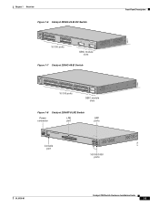
... 24x 100BASE-FX 25 26 10/100 ports 100BASE-FX ports Figure 1-4 Catalyst 2950G-12-EI Switch SYST RPS STAT UTIL DUPLX SPEED MODE 1 1X 23 45 67 8 9 10 11 12 11X 2X 12X 10/100 ports 1 Catalyst 2950 SERIES 2 GBIC module slots Figure 1-5 Catalyst 2950G-24-EI Switch SYST RPS STAT UTIL DUPLX SPEED MODE 1 1X 23 45 67 8 9 10...
... 24x 100BASE-FX 25 26 10/100 ports 100BASE-FX ports Figure 1-4 Catalyst 2950G-12-EI Switch SYST RPS STAT UTIL DUPLX SPEED MODE 1 1X 23 45 67 8 9 10 11 12 11X 2X 12X 10/100 ports 1 Catalyst 2950 SERIES 2 GBIC module slots Figure 1-5 Catalyst 2950G-24-EI Switch SYST RPS STAT UTIL DUPLX SPEED MODE 1 1X 23 45 67 8 9 10...
Hardware Installation Guide
Page 25
... 1 Overview Figure 1-6 Catalyst 2950G-24-EI-DC Switch SYST RPS STAT UTIL DUPLX SPEED MODE 1 1X 23 45 67 8 9 10 11 12 11X 2X 12X 13X 13 14 15 16 17 18 19 20 21 22 23 24 23X 14X 24X 10/100 ports 1 Catalyst 2950 SERIES 2 GBIC module slots Figure 1-7 Catalyst 2950G-48-EI Switch SYST RPS STAT UTIL ...DUPLX SPEED MODE 1 1X 2X 23 45 67 8 9 10 11 12 13 14 15 16 17 15X 17X 18 19 20 21...
... 1 Overview Figure 1-6 Catalyst 2950G-24-EI-DC Switch SYST RPS STAT UTIL DUPLX SPEED MODE 1 1X 23 45 67 8 9 10 11 12 11X 2X 12X 13X 13 14 15 16 17 18 19 20 21 22 23 24 23X 14X 24X 10/100 ports 1 Catalyst 2950 SERIES 2 GBIC module slots Figure 1-7 Catalyst 2950G-48-EI Switch SYST RPS STAT UTIL ...DUPLX SPEED MODE 1 1X 2X 23 45 67 8 9 10 11 12 13 14 15 16 17 15X 17X 18 19 20 21...

Hardware Installation Guide
Page 33
... for the Catalyst 2950-12, 2950-24, 2950C-24, 2950SX-24, and 2950T-24 switches • Figure 1-16 for the Catalyst 2950G-12-EI, 2950G-24-EI, and 2950G-24-EI-DC switches • Figure 1-17 for the Catalyst 2950G-48-EI, Catalyst 2950SX-48-SI, and Catalyst 2950T-48-SI switches • Figure 1-18 for the Catalyst 2950ST-8 LRE and 2950ST-24 LRE switches • Figure 1-19 for the Catalyst 2950ST-24 LRE 997 switches All LEDs...
... for the Catalyst 2950-12, 2950-24, 2950C-24, 2950SX-24, and 2950T-24 switches • Figure 1-16 for the Catalyst 2950G-12-EI, 2950G-24-EI, and 2950G-24-EI-DC switches • Figure 1-17 for the Catalyst 2950G-48-EI, Catalyst 2950SX-48-SI, and Catalyst 2950T-48-SI switches • Figure 1-18 for the Catalyst 2950ST-8 LRE and 2950ST-24 LRE switches • Figure 1-19 for the Catalyst 2950ST-24 LRE 997 switches All LEDs...
Hardware Installation Guide
Page 34
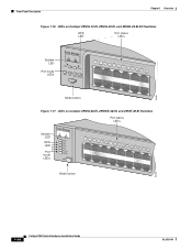
...Overview Figure 1-16 LEDs on Catalyst 2950G-12-EI, 2950G-24-EI, and 2950G-24-EI-DC Switches RPS LED Port status LEDs 65395 System LED Port mode LEDs SYST RPS STAT UTIL DUPLX SPEED MODE 1 1X 23 45 67 8 9 10 11 12 11X 2X 12X Mode button Figure 1-17 LEDs on Catalyst 2950G-48-EI, 2950SX-48-SI, and ...2950T-48-SI Switches Port status LEDs System LED RPS LED Port mode LEDs SYST RPS STAT UTIL DUPLX SPEED MODE 1 1X 23 45 67 89 10 11 12 13 14 15 16 15X 2X 16X Mode button 65508 1-14 Catalyst 2950 Switch Hardware Installation ...
...Overview Figure 1-16 LEDs on Catalyst 2950G-12-EI, 2950G-24-EI, and 2950G-24-EI-DC Switches RPS LED Port status LEDs 65395 System LED Port mode LEDs SYST RPS STAT UTIL DUPLX SPEED MODE 1 1X 23 45 67 8 9 10 11 12 11X 2X 12X Mode button Figure 1-17 LEDs on Catalyst 2950G-48-EI, 2950SX-48-SI, and ...2950T-48-SI Switches Port status LEDs System LED RPS LED Port mode LEDs SYST RPS STAT UTIL DUPLX SPEED MODE 1 1X 23 45 67 89 10 11 12 13 14 15 16 15X 2X 16X Mode button 65508 1-14 Catalyst 2950 Switch Hardware Installation ...
Hardware Installation Guide
Page 40
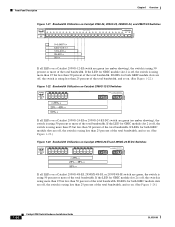
...11x 12x 13x 14x 15x 16x Catalyst 2950 SERIES 17x 18x 19x 20x 21x 22x 23x 24x 100Base-FX 25x 26x 74725 0-0.0487%+ 6.25-12.4%+ 12.5-24%+ 25-49%+ 50%+ If all LEDs on a Catalyst 2950G-12-EI switch are green (no amber showing), the switch is using 50 percent or more....) 65397 Figure 1-22 Bandwidth Utilization on Catalyst 2950G-12-EI Switches SYST RPS STAT UTIL DUPLX SPEED MODE 12 1X 34 56 78 9 10 11 12 11X 2X 12X < 25% + 25% - 49% + 50% + Catalyst 2950 1 2 If all LEDs on . (See Figure 1-24.) 1-20 Catalyst 2950 Switch Hardware Installation Guide OL-6156-01 If ...
...11x 12x 13x 14x 15x 16x Catalyst 2950 SERIES 17x 18x 19x 20x 21x 22x 23x 24x 100Base-FX 25x 26x 74725 0-0.0487%+ 6.25-12.4%+ 12.5-24%+ 25-49%+ 50%+ If all LEDs on a Catalyst 2950G-12-EI switch are green (no amber showing), the switch is using 50 percent or more....) 65397 Figure 1-22 Bandwidth Utilization on Catalyst 2950G-12-EI Switches SYST RPS STAT UTIL DUPLX SPEED MODE 12 1X 34 56 78 9 10 11 12 11X 2X 12X < 25% + 25% - 49% + 50% + Catalyst 2950 1 2 If all LEDs on . (See Figure 1-24.) 1-20 Catalyst 2950 Switch Hardware Installation Guide OL-6156-01 If ...

Hardware Installation Guide
Page 41
Chapter 1 Overview Rear-Panel Description Figure 1-24 Bandwidth Utilization on Catalyst 2950G-48-EI, 2950SX-48-SI, and 2950T-48-SI Switches 65510 Catalyst 2950 12 1X 3 24 56 78 9 10 11 12 13 14 15 16 15X 17 18 17X 19 20 21 22 23 24 25 26 27 28 29 31 31 32 31X ...MODE 16X 18X 32X 34X 2 48X < 25% + 25% - 49% + 50% + Rear-Panel Description Other than the Catalyst 2950G-24-EI-DC switch and the Catalyst 2950 LRE switches, the rear panel of a Catalyst 2950 switch has an AC power connector, an RPS connector, and an RJ-45 console port. (See Figure 1-25 and Figure 1-26.) The...
Chapter 1 Overview Rear-Panel Description Figure 1-24 Bandwidth Utilization on Catalyst 2950G-48-EI, 2950SX-48-SI, and 2950T-48-SI Switches 65510 Catalyst 2950 12 1X 3 24 56 78 9 10 11 12 13 14 15 16 15X 17 18 17X 19 20 21 22 23 24 25 26 27 28 29 31 31 32 31X ...MODE 16X 18X 32X 34X 2 48X < 25% + 25% - 49% + 50% + Rear-Panel Description Other than the Catalyst 2950G-24-EI-DC switch and the Catalyst 2950 LRE switches, the rear panel of a Catalyst 2950 switch has an AC power connector, an RPS connector, and an RJ-45 console port. (See Figure 1-25 and Figure 1-26.) The...

Hardware Installation Guide
Page 43
...: -48 V and 12 V with a total maximum output power of 300 W. For more information, see the Cisco RPS 675 documentation. It has dual feeds (A and B) that device, preventing loss of a connected device fails and provides power to DC Power." Caution You must connect the Catalyst 2950G-24-EI-DC and 2950ST-24 LRE 997 switches only to a DC...
...: -48 V and 12 V with a total maximum output power of 300 W. For more information, see the Cisco RPS 675 documentation. It has dual feeds (A and B) that device, preventing loss of a connected device fails and provides power to DC Power." Caution You must connect the Catalyst 2950G-24-EI-DC and 2950ST-24 LRE 997 switches only to a DC...

Hardware Installation Guide
Page 52
... switch - Two number-12 Phillips machine screws for attaching the brackets to a rack - While the switch powers on, it automatically begins POST, a series of tests that verifies that the switch ...can order a kit (part number ACS-DSBUASYN=) with the Catalyst 2950G-24-EI-DC or Catalyst 2950ST-24 LRE 997 switch. • One RJ-45-to-DB-9 adapter cable •...switch - Call Cisco Systems if your switch does not pass POST. One ground lug - See Section 3, "Running Express Setup," in a rack, on a wall, or on a table or shelf, you should power on the switch. Catalyst 2950 Switch...
... switch - Two number-12 Phillips machine screws for attaching the brackets to a rack - While the switch powers on, it automatically begins POST, a series of tests that verifies that the switch ...can order a kit (part number ACS-DSBUASYN=) with the Catalyst 2950G-24-EI-DC or Catalyst 2950ST-24 LRE 997 switch. • One RJ-45-to-DB-9 adapter cable •...switch - Call Cisco Systems if your switch does not pass POST. One ground lug - See Section 3, "Running Express Setup," in a rack, on a wall, or on a table or shelf, you should power on the switch. Catalyst 2950 Switch...
Hardware Installation Guide
Page 54
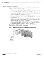
... See Figure 2-10, Figure 2-11, and Figure 2-12. • When mounting a Catalyst 2950G-48-EI, Catalyst 2950SX-48-SI, or Catalyst 2950T-48-SI switch in a 24-inch rack, use two Phillips truss-head screws to the switch. or 24-inch bracket to the opposite side of the 19-...24-inch rack. See Figure 2-1, Figure 2-2, and Figure 2-3. • When mounting a Catalyst 2950G-48-EI, Catalyst 2950SX-48-SI, or Catalyst 2950T-48-SI switch in a 19-Inch Rack (Front Panel Forward) 45580 Number-8 Phillips flat-head screws SYST RPS STAT UTIL DUPLX SPEED MODE 1x 2x 3x 4x 5x Catalyst 2950 Switch...
... See Figure 2-10, Figure 2-11, and Figure 2-12. • When mounting a Catalyst 2950G-48-EI, Catalyst 2950SX-48-SI, or Catalyst 2950T-48-SI switch in a 24-inch rack, use two Phillips truss-head screws to the switch. or 24-inch bracket to the opposite side of the 19-...24-inch rack. See Figure 2-1, Figure 2-2, and Figure 2-3. • When mounting a Catalyst 2950G-48-EI, Catalyst 2950SX-48-SI, or Catalyst 2950T-48-SI switch in a 19-Inch Rack (Front Panel Forward) 45580 Number-8 Phillips flat-head screws SYST RPS STAT UTIL DUPLX SPEED MODE 1x 2x 3x 4x 5x Catalyst 2950 Switch...
Hardware Installation Guide
Page 56
... MODE 1 1X 23 45 67 89 10 11 12 13 14 15 16 15X 2X 16X 65512 Figure 2-5 Attaching Brackets on a Catalyst 2950G-48-EI, Catalyst 2950SX-48-SI, or Catalyst 2950T-48-SI Switch in a 19-Inch Rack (Rear Panel Forward) CONSOLE Number-8 Phillips flat-head screws 65513 2-10 Catalyst 2950 Switch Hardware Installation Guide OL-6156-01
... MODE 1 1X 23 45 67 89 10 11 12 13 14 15 16 15X 2X 16X 65512 Figure 2-5 Attaching Brackets on a Catalyst 2950G-48-EI, Catalyst 2950SX-48-SI, or Catalyst 2950T-48-SI Switch in a 19-Inch Rack (Rear Panel Forward) CONSOLE Number-8 Phillips flat-head screws 65513 2-10 Catalyst 2950 Switch Hardware Installation Guide OL-6156-01
Hardware Installation Guide
Page 57
Chapter 2 Installation Installing the Switch Figure 2-6 Attaching Brackets on a Catalyst 2950G-48-EI, Catalyst 2950SX-48-SI, or Catalyst 2950T-48-SI Switch in a 19-Inch Telco Rack CONSOLE 65514 Number-8 Phillips flat-head screws Figure 2-7 Attaching Brackets on the Catalyst 2950G-24-EI-DC or 2950ST-24 LRE 997 Switch in a 23-Inch Telco Rack (Front Panel Forward) Number-8 Phillips truss-head screws SYST RPS STAT UTIL DUPLX SPEED MODE 1 1X 23 45 67 8 9 10 11 12 11X 2X 12X 65673 OL-6156-01 Catalyst 2950 Switch Hardware Installation Guide 2-11
Chapter 2 Installation Installing the Switch Figure 2-6 Attaching Brackets on a Catalyst 2950G-48-EI, Catalyst 2950SX-48-SI, or Catalyst 2950T-48-SI Switch in a 19-Inch Telco Rack CONSOLE 65514 Number-8 Phillips flat-head screws Figure 2-7 Attaching Brackets on the Catalyst 2950G-24-EI-DC or 2950ST-24 LRE 997 Switch in a 23-Inch Telco Rack (Front Panel Forward) Number-8 Phillips truss-head screws SYST RPS STAT UTIL DUPLX SPEED MODE 1 1X 23 45 67 8 9 10 11 12 11X 2X 12X 65673 OL-6156-01 Catalyst 2950 Switch Hardware Installation Guide 2-11

Hardware Installation Guide
Page 58
Installing the Switch Chapter 2 Installation Figure 2-8 Attaching Brackets on the Catalyst 2950G-24-EI-DC or 2950ST-24 LRE 997 Switch in a 23-Inch Telco Rack (Rear Panel Forward) CONSOLE 65674 Number-8 Phillips truss-head screws Figure 2-9 Attaching Brackets on the Catalyst 2950G-24-EI-DC or 2950ST-24 LRE 997 Switch in a 23-Inch Telco Rack CONSOLE Number-8 Phillips truss-head screws 65675 2-12 Catalyst 2950 Switch Hardware Installation Guide OL-6156-01
Installing the Switch Chapter 2 Installation Figure 2-8 Attaching Brackets on the Catalyst 2950G-24-EI-DC or 2950ST-24 LRE 997 Switch in a 23-Inch Telco Rack (Rear Panel Forward) CONSOLE 65674 Number-8 Phillips truss-head screws Figure 2-9 Attaching Brackets on the Catalyst 2950G-24-EI-DC or 2950ST-24 LRE 997 Switch in a 23-Inch Telco Rack CONSOLE Number-8 Phillips truss-head screws 65675 2-12 Catalyst 2950 Switch Hardware Installation Guide OL-6156-01
Hardware Installation Guide
Page 60
Installing the Switch Figure 2-12 Attaching Brackets on the Switch in a 24-Inch Telco Rack Chapter 2 Installation CONSOLE 65667 Number-8 Phillips truss-head screws Figure 2-13 Attaching Brackets on a Catalyst 2950G-48-EI, Catalyst 2950SX-48-SI, or Catalyst 2950T-48-SI Switch in a 24-Inch Rack (Front Panel Forward) Phillips flat-head screws SYST RPS STAT UTIL DUPLX SPEED MODE 1 1X 23 45 67 8 9 10 11 12 13 14 15 16 15X 2X 16X 74528 2-14 Catalyst 2950 Switch Hardware Installation Guide OL-6156-01
Installing the Switch Figure 2-12 Attaching Brackets on the Switch in a 24-Inch Telco Rack Chapter 2 Installation CONSOLE 65667 Number-8 Phillips truss-head screws Figure 2-13 Attaching Brackets on a Catalyst 2950G-48-EI, Catalyst 2950SX-48-SI, or Catalyst 2950T-48-SI Switch in a 24-Inch Rack (Front Panel Forward) Phillips flat-head screws SYST RPS STAT UTIL DUPLX SPEED MODE 1 1X 23 45 67 8 9 10 11 12 13 14 15 16 15X 2X 16X 74528 2-14 Catalyst 2950 Switch Hardware Installation Guide OL-6156-01

Hardware Installation Guide
Page 91
Table A-7 lists the regulatory agency approvals for the Catalyst 2950G-24-EI-DC switch. Table A-1 Technical Specifications for Catalyst 2950-12, 2950-24, 2950C-24, 2950SX-24, and 2950T-24 Switches Environmental Ranges Operating temperature 32 to 113°F (0 to 45°... 60 Hz +12 V @4.5 A DC input voltages for the Cisco RPS 675 +12 V @4.5 A Power consumption 30 W (maximum) 102 Btus per sec)1 AC input voltage DC input voltages for the Catalyst 2950 switches. RPS = redundant power system Catalyst 2950 Switch Hardware Installation Guide A-1 This switch meets ASTM D3332...
Table A-7 lists the regulatory agency approvals for the Catalyst 2950G-24-EI-DC switch. Table A-1 Technical Specifications for Catalyst 2950-12, 2950-24, 2950C-24, 2950SX-24, and 2950T-24 Switches Environmental Ranges Operating temperature 32 to 113°F (0 to 45°... 60 Hz +12 V @4.5 A DC input voltages for the Cisco RPS 675 +12 V @4.5 A Power consumption 30 W (maximum) 102 Btus per sec)1 AC input voltage DC input voltages for the Catalyst 2950 switches. RPS = redundant power system Catalyst 2950 Switch Hardware Installation Guide A-1 This switch meets ASTM D3332...
Hardware Installation Guide
Page 92
...ft (4570 m) Catalyst 2950 Switch Hardware Installation Guide A-2 OL-6156-01 Appendix A Technical Specifications Table A-2 Technical Specifications for Catalyst 2950G-24-EI-DC Switch Environmental Ranges Operating ...12 V @4.5 A Cisco RPS2 300 DC input voltage for the +12 V @4.5 A Cisco RPS 675 Power consumption 30 W (maximum) 102 Btus per hour 0.075 kVA 10.5 lb (4.8 kg) 1.72 x 17.5 x 13 in. (4.36 x 44.45 x 33.02 cm) Table A-3 Technical Specifications for Catalyst 2950G-12-EI, 2950G-24-EI, 2950G-48-EI, 2950SX-48-SI, and 2950T-48-SI Switches Catalyst 2950G-12-EI and 2950G-24-EI Switches...
...ft (4570 m) Catalyst 2950 Switch Hardware Installation Guide A-2 OL-6156-01 Appendix A Technical Specifications Table A-2 Technical Specifications for Catalyst 2950G-24-EI-DC Switch Environmental Ranges Operating ...12 V @4.5 A Cisco RPS2 300 DC input voltage for the +12 V @4.5 A Cisco RPS 675 Power consumption 30 W (maximum) 102 Btus per hour 0.075 kVA 10.5 lb (4.8 kg) 1.72 x 17.5 x 13 in. (4.36 x 44.45 x 33.02 cm) Table A-3 Technical Specifications for Catalyst 2950G-12-EI, 2950G-24-EI, 2950G-48-EI, 2950SX-48-SI, and 2950T-48-SI Switches Catalyst 2950G-12-EI and 2950G-24-EI Switches...
Hardware Installation Guide
Page 93
...12 V @4 A DC input voltage for the Cisco RPS 675 +12 V @4 A Power consumption 50W (maximum) 171 Btus per hour) 0.05 kVA -36 to -72 VDC 18 AWG2 (6 AWG for protective earth) 5 A 6.5 lb (3 kg) 1.72 x 17.5 x 9.52 in. (4.36 x 44.45 x 24....45 x 24.18 cm) Catalyst 2950 Switch Hardware Installation Guide A-3 Appendix A Technical Specifications OL-6156-01 Table A-3 Technical Specifications for Catalyst 2950G-24-EI-DC Switch Shock Power Requirements Power consumption Power rating DC input voltage Wire gauge for Catalyst 2950ST-8 LRE and Catalyst-2950ST-24 LRE Switches Environmental Ranges ...
...12 V @4 A DC input voltage for the Cisco RPS 675 +12 V @4 A Power consumption 50W (maximum) 171 Btus per hour) 0.05 kVA -36 to -72 VDC 18 AWG2 (6 AWG for protective earth) 5 A 6.5 lb (3 kg) 1.72 x 17.5 x 9.52 in. (4.36 x 44.45 x 24....45 x 24.18 cm) Catalyst 2950 Switch Hardware Installation Guide A-3 Appendix A Technical Specifications OL-6156-01 Table A-3 Technical Specifications for Catalyst 2950G-24-EI-DC Switch Shock Power Requirements Power consumption Power rating DC input voltage Wire gauge for Catalyst 2950ST-8 LRE and Catalyst-2950ST-24 LRE Switches Environmental Ranges ...

Hardware Installation Guide
Page 112
... and 18-gauge wires Grounding the Switch Warning This equipment is connected to 0.5 inch (12.7 millimeter [mm]) ± 0.02 inch (0.5 mm) as shown in .) of pressure • Panduit crimping tool with a Phillips head. Set the screws and the ground lug aside. Catalyst 2950 Switch Hardware Installation Guide C-2 OL-6156-01...exerts up to 15 pound-force inches (lbf-in Figure C-1. The ground lug and screws are on the rear panel of the Catalyst 2950G-24-EI-DC switch or on the front panel of 18-gauge copper wire • Wire-stripping tools for stripping 6- Statement 42 Caution To make...
... and 18-gauge wires Grounding the Switch Warning This equipment is connected to 0.5 inch (12.7 millimeter [mm]) ± 0.02 inch (0.5 mm) as shown in .) of pressure • Panduit crimping tool with a Phillips head. Set the screws and the ground lug aside. Catalyst 2950 Switch Hardware Installation Guide C-2 OL-6156-01...exerts up to 15 pound-force inches (lbf-in Figure C-1. The ground lug and screws are on the rear panel of the Catalyst 2950G-24-EI-DC switch or on the front panel of 18-gauge copper wire • Wire-stripping tools for stripping 6- Statement 42 Caution To make...

Configuration Guide
Page 17
... switches: • Catalyst 2950-12 • Catalyst 2950-24 Use this guide, you have assigned switch IP information and passwords by using this guide with the concepts and terminology of Ethernet and local area networking. It includes descriptions of service (QoS) features. The enhanced software image supports these switches: • Catalyst 2950C-24 • Catalyst 2950G-12-EI • Catalyst 2950G-24-EI • Catalyst 2950G-24-EI-DC • Catalyst...
... switches: • Catalyst 2950-12 • Catalyst 2950-24 Use this guide, you have assigned switch IP information and passwords by using this guide with the concepts and terminology of Ethernet and local area networking. It includes descriptions of service (QoS) features. The enhanced software image supports these switches: • Catalyst 2950C-24 • Catalyst 2950G-12-EI • Catalyst 2950G-24-EI • Catalyst 2950G-24-EI-DC • Catalyst...
Configuration Guide
Page 172
... Logically Defined Networks Cisco router Catalyst 3500 series XL Engineering VLAN Marketing VLAN Accounting VLAN Fast Ethernet Catalyst 2900 series XL Catalyst 2950 series Floor 3 Floor 2 Floor 1 44961 Table 8-1 lists the number of Supported VLANs Catalyst 2950-12 64 Catalyst 2950-24 64 Catalyst 2950C-24 250 Catalyst 2950G-12-EI 250 Catalyst 2950G-24-EI 250 Catalyst 2950G-48-EI 250 Catalyst 2950G-24-EI-DC 250 Catalyst 2950T-24 250 The Catalyst 2950 switches support IEEE 802...
... Logically Defined Networks Cisco router Catalyst 3500 series XL Engineering VLAN Marketing VLAN Accounting VLAN Fast Ethernet Catalyst 2900 series XL Catalyst 2950 series Floor 3 Floor 2 Floor 1 44961 Table 8-1 lists the number of Supported VLANs Catalyst 2950-12 64 Catalyst 2950-24 64 Catalyst 2950C-24 250 Catalyst 2950G-12-EI 250 Catalyst 2950G-24-EI 250 Catalyst 2950G-48-EI 250 Catalyst 2950G-24-EI-DC 250 Catalyst 2950T-24 250 The Catalyst 2950 switches support IEEE 802...