
Hardware Installation Guide
Page 21
... switch features: • Hardware - Catalyst 2950-24 switch-24 10/100 Ethernet ports - Overview CH A P T E R 1 This chapter provides information about these topics: • Setting up the Switch, page 1-1 • Features, page 1-1 • Front-Panel Description, page 1-3 • Rear-Panel Description, page 1-21 • Management Options, page 1-24 Setting up the Switch See the Catalyst 2950 Switch Getting Started Guide for both AC- Catalyst 2950-12 switch-12...
... switch features: • Hardware - Catalyst 2950-24 switch-24 10/100 Ethernet ports - Overview CH A P T E R 1 This chapter provides information about these topics: • Setting up the Switch, page 1-1 • Features, page 1-1 • Front-Panel Description, page 1-3 • Rear-Panel Description, page 1-21 • Management Options, page 1-24 Setting up the Switch See the Catalyst 2950 Switch Getting Started Guide for both AC- Catalyst 2950-12 switch-12...

Hardware Installation Guide
Page 22
...-Mbps and full-duplex settings - Features Chapter 1 Overview - On Catalyst 2950G-12-EI, 2950G-24-EI, 2950G-24-EI-DC, and 2950G-48-EI switches, support for the Catalyst 2950 LRE switches. - Checks for a list of the four uplink ports are active at one time.) - Catalyst 2950G-24-EI-DC-24 10/100 Ethernet ports and 2 GBIC module slots with DC...
...-Mbps and full-duplex settings - Features Chapter 1 Overview - On Catalyst 2950G-12-EI, 2950G-24-EI, 2950G-24-EI-DC, and 2950G-48-EI switches, support for the Catalyst 2950 LRE switches. - Checks for a list of the four uplink ports are active at one time.) - Catalyst 2950G-24-EI-DC-24 10/100 Ethernet ports and 2 GBIC module slots with DC...

Hardware Installation Guide
Page 23
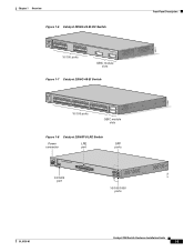
... than the Catalyst 2950ST-24 LRE 997 switch, the front panel of the Catalyst 2950 LRE switches also contain the console port and AC power connector. In Table 1-1, Yes means that uses AC input and supplies DC output to the switch Certain Cisco LRE customer premises equipment (CPE) devices are not supported by certain Catalyst 2950 LRE switches. Figure 1-1 Catalyst 2950-12 Switch 45568 SYST...
... than the Catalyst 2950ST-24 LRE 997 switch, the front panel of the Catalyst 2950 LRE switches also contain the console port and AC power connector. In Table 1-1, Yes means that uses AC input and supplies DC output to the switch Certain Cisco LRE customer premises equipment (CPE) devices are not supported by certain Catalyst 2950 LRE switches. Figure 1-1 Catalyst 2950-12 Switch 45568 SYST...

Hardware Installation Guide
Page 24
... 100BASE-FX 25 26 10/100 ports 100BASE-FX ports Figure 1-4 Catalyst 2950G-12-EI Switch SYST RPS STAT UTIL DUPLX SPEED MODE 1 1X 23 45 67 8 9 10 11 12 11X 2X 12X 10/100 ports 1 Catalyst 2950 SERIES 2 GBIC module slots Figure 1-5 Catalyst 2950G-24-EI Switch SYST RPS STAT UTIL DUPLX SPEED MODE 1 1X 23 45 67...
... 100BASE-FX 25 26 10/100 ports 100BASE-FX ports Figure 1-4 Catalyst 2950G-12-EI Switch SYST RPS STAT UTIL DUPLX SPEED MODE 1 1X 23 45 67 8 9 10 11 12 11X 2X 12X 10/100 ports 1 Catalyst 2950 SERIES 2 GBIC module slots Figure 1-5 Catalyst 2950G-24-EI Switch SYST RPS STAT UTIL DUPLX SPEED MODE 1 1X 23 45 67...
Hardware Installation Guide
Page 25
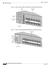
... UTIL DUPLX SPEED MODE 1 1X 23 45 67 8 9 10 11 12 11X 2X 12X 13X 13 14 15 16 17 18 19 20 21 22 23 24 23X 14X 24X 10/100 ports 1 Catalyst 2950 SERIES 2 GBIC module slots Figure 1-7 Catalyst 2950G-48-EI Switch SYST RPS STAT UTIL DUPLX SPEED MODE 1 1X 2X 23 45... 67 8 9 10 11 12 13 14 15 16 17 15X 17X 18 19 20 21...
... UTIL DUPLX SPEED MODE 1 1X 23 45 67 8 9 10 11 12 11X 2X 12X 13X 13 14 15 16 17 18 19 20 21 22 23 24 23X 14X 24X 10/100 ports 1 Catalyst 2950 SERIES 2 GBIC module slots Figure 1-7 Catalyst 2950G-48-EI Switch SYST RPS STAT UTIL DUPLX SPEED MODE 1 1X 2X 23 45... 67 8 9 10 11 12 13 14 15 16 17 15X 17X 18 19 20 21...
Hardware Installation Guide
Page 26
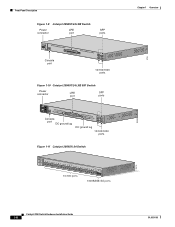
....00A-1/02R.75A/TA2I0N500G--26400HVZ~ MODE SYST RPS STAT SPEED CONSOLE 1 2 3 4 5 6 7 8 9 10 11 12 Console port 13 14 15 16 17 18 19 20 21 22 23 24 Catalyst 2950 SERIES LRE 1 2 1 2 10/100/1000 ports Figure 1-10 Catalyst 2950ST-24 LRE 997 Switch Power connector LRE port SFP ports - ++ A INPCUUTR:RE3N6T- SYST RPS STAT SPEED MODE...
....00A-1/02R.75A/TA2I0N500G--26400HVZ~ MODE SYST RPS STAT SPEED CONSOLE 1 2 3 4 5 6 7 8 9 10 11 12 Console port 13 14 15 16 17 18 19 20 21 22 23 24 Catalyst 2950 SERIES LRE 1 2 1 2 10/100/1000 ports Figure 1-10 Catalyst 2950ST-24 LRE 997 Switch Power connector LRE port SFP ports - ++ A INPCUUTR:RE3N6T- SYST RPS STAT SPEED MODE...
Hardware Installation Guide
Page 27
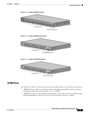
...6156-01 Catalyst 2950 Switch Hardware Installation Guide 1-7 Chapter 1 Overview Figure 1-12 Catalyst 2950T-24 Switch Front-Panel Description 47337 SYST RPS STAT UTIL DUPLX SPEED MODE 1x 2x 3x 4x 5x 6x 7x 8x 9x 10x 11x 10Base-T / 100Base-TX 12x 13x 14x 15x 16x 17x 18x 19x 20x 21x 22x 23x Catalyst 2950 SERIES 24x... 45 46 47 48 47X 32X 34X 48X 10/100 ports Catalyst 2950 SERIES 1 2 1000BASE-SX ports Figure 1-14 Catalyst 2950T-48-SI Switch 97626 SYST RPS STAT UTIL DUPLX SPEED MODE 1 1X 2X 23 45 67 8 9 10 11 12 13 14 15 16 17 15X 17X 18 19 20 21 ...
...6156-01 Catalyst 2950 Switch Hardware Installation Guide 1-7 Chapter 1 Overview Figure 1-12 Catalyst 2950T-24 Switch Front-Panel Description 47337 SYST RPS STAT UTIL DUPLX SPEED MODE 1x 2x 3x 4x 5x 6x 7x 8x 9x 10x 11x 10Base-T / 100Base-TX 12x 13x 14x 15x 16x 17x 18x 19x 20x 21x 22x 23x Catalyst 2950 SERIES 24x... 45 46 47 48 47X 32X 34X 48X 10/100 ports Catalyst 2950 SERIES 1 2 1000BASE-SX ports Figure 1-14 Catalyst 2950T-48-SI Switch 97626 SYST RPS STAT UTIL DUPLX SPEED MODE 1 1X 2X 23 45 67 8 9 10 11 12 13 14 15 16 17 15X 17X 18 19 20 21 ...

Hardware Installation Guide
Page 32
...you must also install a mode-conditioning patch cord between the fiber-optic cable plant and the receiving port on the Catalyst 2950 LRE switch. Use only Cisco-approved SFP modules on the 1000BASE-ZX SFP module at each end of the link. Note When using dispersion-shifted .... For more information about these SFP modules, see your SFP module documentation. 1-12 Catalyst 2950 Switch Hardware Installation Guide OL-6156-01 When using a non-Cisco approved SFP module, remove the module from the switch, and replace it with 62.5-micron diameter MMF, you are using the LX/...
...you must also install a mode-conditioning patch cord between the fiber-optic cable plant and the receiving port on the Catalyst 2950 LRE switch. Use only Cisco-approved SFP modules on the 1000BASE-ZX SFP module at each end of the link. Note When using dispersion-shifted .... For more information about these SFP modules, see your SFP module documentation. 1-12 Catalyst 2950 Switch Hardware Installation Guide OL-6156-01 When using a non-Cisco approved SFP module, remove the module from the switch, and replace it with 62.5-micron diameter MMF, you are using the LX/...

Hardware Installation Guide
Page 33
... Catalyst 2950-12, 2950-24, 2950C-24, 2950SX-24, and 2950T-24 switches • Figure 1-16 for the Catalyst 2950G-12-EI, 2950G-24-EI, and 2950G-24-EI-DC switches • Figure 1-17 for the Catalyst 2950G-48-EI, Catalyst 2950SX-48-SI, and Catalyst 2950T-48-SI switches • Figure 1-18 for the Catalyst 2950ST-8 LRE and 2950ST-24 LRE switches • Figure 1-19 for the Catalyst 2950ST-24 LRE 997 switches...
... Catalyst 2950-12, 2950-24, 2950C-24, 2950SX-24, and 2950T-24 switches • Figure 1-16 for the Catalyst 2950G-12-EI, 2950G-24-EI, and 2950G-24-EI-DC switches • Figure 1-17 for the Catalyst 2950G-48-EI, Catalyst 2950SX-48-SI, and Catalyst 2950T-48-SI switches • Figure 1-18 for the Catalyst 2950ST-8 LRE and 2950ST-24 LRE switches • Figure 1-19 for the Catalyst 2950ST-24 LRE 997 switches...
Hardware Installation Guide
Page 34
... Figure 1-16 LEDs on Catalyst 2950G-12-EI, 2950G-24-EI, and 2950G-24-EI-DC Switches RPS LED Port status LEDs 65395 System LED Port mode LEDs SYST RPS STAT UTIL DUPLX SPEED MODE 1 1X 23 45 67 8 9 10 11 12 11X 2X 12X Mode button Figure 1-17 LEDs on Catalyst 2950G-48-EI, 2950SX-48...-SI, and 2950T-48-SI Switches Port status LEDs System LED RPS LED Port mode LEDs SYST RPS STAT UTIL DUPLX SPEED MODE 1 1X 23 45 67 89 10 11 12 13 14 15 16 15X 2X 16X Mode button 65508 1-14 Catalyst 2950 Switch Hardware Installation Guide OL-6156-01
... Figure 1-16 LEDs on Catalyst 2950G-12-EI, 2950G-24-EI, and 2950G-24-EI-DC Switches RPS LED Port status LEDs 65395 System LED Port mode LEDs SYST RPS STAT UTIL DUPLX SPEED MODE 1 1X 23 45 67 8 9 10 11 12 11X 2X 12X Mode button Figure 1-17 LEDs on Catalyst 2950G-48-EI, 2950SX-48...-SI, and 2950T-48-SI Switches Port status LEDs System LED RPS LED Port mode LEDs SYST RPS STAT UTIL DUPLX SPEED MODE 1 1X 23 45 67 89 10 11 12 13 14 15 16 15X 2X 16X Mode button 65508 1-14 Catalyst 2950 Switch Hardware Installation Guide OL-6156-01

Hardware Installation Guide
Page 35
B 72 V :2-1 A SYST RPS STAT SPEED MODE CONSOLE STAT LED Speed Mode LED button 1 2 3 4 5 6 7 8 9 10 11 12 89364 OL-6156-01 Catalyst 2950 Switch Hardware Installation Guide 1-15 Chapter 1 Overview Front-Panel Description Figure 1-18 LEDs on Catalyst 2950ST-8 LRE and 2950ST-24 LRE Switches System LED Redundant power system LED Port status LEDs 81187 110.00A-1/02R.75A...
B 72 V :2-1 A SYST RPS STAT SPEED MODE CONSOLE STAT LED Speed Mode LED button 1 2 3 4 5 6 7 8 9 10 11 12 89364 OL-6156-01 Catalyst 2950 Switch Hardware Installation Guide 1-15 Chapter 1 Overview Front-Panel Description Figure 1-18 LEDs on Catalyst 2950ST-8 LRE and 2950ST-24 LRE Switches System LED Redundant power system LED Port status LEDs 81187 110.00A-1/02R.75A...
Hardware Installation Guide
Page 39
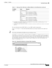
... 50 percent of the total bandwidth, and so on Catalyst 2950-12 Switches SYST RPS STAT UTIL DUPLX SPEED MODE 1x 2x 3x 4x 5x 6x 7x 8x 10Base-T / 100Base-TX 9x 10x 11x 12x Catalyst 2950 SERIES 47267 0-0.0487%+ 6.25-12.4%+ 12.5-24%+ 25-49%+ 50%+ OL-6156-01 Catalyst 2950 Switch Hardware Installation Guide 1-19 If only the far-left... in Different Modes for Uplink Port 1 and Uplink Port 2 correspond either to the SFP module port or to the 10/100/1000 port, depending on a Catalyst 2950-12, 2950-24, 2950C-24, 2950SX-24, or 2950T-24 switch are green (no amber showing), the...
... 50 percent of the total bandwidth, and so on Catalyst 2950-12 Switches SYST RPS STAT UTIL DUPLX SPEED MODE 1x 2x 3x 4x 5x 6x 7x 8x 10Base-T / 100Base-TX 9x 10x 11x 12x Catalyst 2950 SERIES 47267 0-0.0487%+ 6.25-12.4%+ 12.5-24%+ 25-49%+ 50%+ OL-6156-01 Catalyst 2950 Switch Hardware Installation Guide 1-19 If only the far-left... in Different Modes for Uplink Port 1 and Uplink Port 2 correspond either to the SFP module port or to the 10/100/1000 port, depending on a Catalyst 2950-12, 2950-24, 2950C-24, 2950SX-24, or 2950T-24 switch are green (no amber showing), the...
Hardware Installation Guide
Page 40
...Catalyst 2950-24, 2950C-24, 2950SX-24, and 2950T-24 Switches SYST RPS STAT UTIL DUPLX SPEED MODE 1x 2x 3x 4x 5x 6x 7x 8x 10Base-T / 100Base-TX 9x 10x 11x 12x 13x 14x 15x 16x Catalyst 2950 SERIES 17x 18x 19x 20x 21x 22x 23x 24x 100Base-FX 25x 26x 74725 0-0.0487%+ 6.25-12.4%+ 12.5-24...%+ 25-49%+ 50%+ If all LEDs on a Catalyst 2950G-12-EI switch are green (no amber showing), the switch is using 50 percent or more...
...Catalyst 2950-24, 2950C-24, 2950SX-24, and 2950T-24 Switches SYST RPS STAT UTIL DUPLX SPEED MODE 1x 2x 3x 4x 5x 6x 7x 8x 10Base-T / 100Base-TX 9x 10x 11x 12x 13x 14x 15x 16x Catalyst 2950 SERIES 17x 18x 19x 20x 21x 22x 23x 24x 100Base-FX 25x 26x 74725 0-0.0487%+ 6.25-12.4%+ 12.5-24...%+ 25-49%+ 50%+ If all LEDs on a Catalyst 2950G-12-EI switch are green (no amber showing), the switch is using 50 percent or more...

Hardware Installation Guide
Page 41
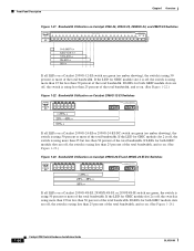
... 65511 12005R@[email protected]~~ AC power connector [email protected]. Chapter 1 Overview Rear-Panel Description Figure 1-24 Bandwidth Utilization on Catalyst 2950G-48-EI, 2950SX-48-SI, and 2950T-48-SI Switches 65510 Catalyst 2950 12 1X 3 24 56 78 9 10 11 12 13 14 15 16 15X 17 18 17X 19 20 21 22 23...
... 65511 12005R@[email protected]~~ AC power connector [email protected]. Chapter 1 Overview Rear-Panel Description Figure 1-24 Bandwidth Utilization on Catalyst 2950G-48-EI, 2950SX-48-SI, and 2950T-48-SI Switches 65510 Catalyst 2950 12 1X 3 24 56 78 9 10 11 12 13 14 15 16 15X 17 18 17X 19 20 21 22 23...

Hardware Installation Guide
Page 43
...Cisco RPS 675 The Cisco RPS 675 has two output levels: -48 V and 12 V with a total maximum output power of 675 W. Cisco RPS Connector Specific Cisco RPS models support specific Catalyst 2950 switches: • Cisco RPS 300 (model PWR300-AC-RPS-N1) • Cisco RPS 675 (model PWR675-AC-RPS-N1=) Cisco RPS 300 The Cisco... external network devices and provides DC power to one failed device at a time. Caution You must connect the Catalyst 2950G-24-EI-DC and 2950ST-24 LRE 997 switches only to a DC-input power source that are diode-OR-ed into a single power block. Warning Attach ...
...Cisco RPS 675 The Cisco RPS 675 has two output levels: -48 V and 12 V with a total maximum output power of 675 W. Cisco RPS Connector Specific Cisco RPS models support specific Catalyst 2950 switches: • Cisco RPS 300 (model PWR300-AC-RPS-N1) • Cisco RPS 675 (model PWR675-AC-RPS-N1=) Cisco RPS 300 The Cisco... external network devices and provides DC power to one failed device at a time. Caution You must connect the Catalyst 2950G-24-EI-DC and 2950ST-24 LRE 997 switches only to a DC-input power source that are diode-OR-ed into a single power block. Warning Attach ...

Hardware Installation Guide
Page 52
...Cisco. One cable guide and one black Phillips machine screw for attaching the brackets to a rack - One RPS connector cover and two number-4 pan-head screws • DC-switch kit containing these steps: Step 1 Step 2 Step 3 Turn off . Two 23-inch rack-mounting brackets (with the Catalyst 2950G-24-EI-DC or Catalyst 2950ST-24...you need to provide an RJ-45-to the switch. Catalyst 2950 Switch Hardware Installation Guide 2-6 OL-6156-01 Disconnect the cables. Verifying Switch Operation Chapter 2 Installation - When the switch begins POST, the system LED is off power ...
...Cisco. One cable guide and one black Phillips machine screw for attaching the brackets to a rack - One RPS connector cover and two number-4 pan-head screws • DC-switch kit containing these steps: Step 1 Step 2 Step 3 Turn off . Two 23-inch rack-mounting brackets (with the Catalyst 2950G-24-EI-DC or Catalyst 2950ST-24...you need to provide an RJ-45-to the switch. Catalyst 2950 Switch Hardware Installation Guide 2-6 OL-6156-01 Disconnect the cables. Verifying Switch Operation Chapter 2 Installation - When the switch begins POST, the system LED is off power ...
Hardware Installation Guide
Page 54
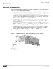
...side of the 19- See Figure 2-10, Figure 2-11, and Figure 2-12. • When mounting a Catalyst 2950G-48-EI, Catalyst 2950SX-48-SI, or Catalyst 2950T-48-SI switch in a 24-inch rack, use depend on the Switch in a 19-inch rack, use two Phillips truss-head screws to one... switch. Follow these guidelines: • When mounting a switch other than a Catalyst 2950G-48-EI, Catalyst 2950SX-48-SI, or Catalyst 2950T-48-SI switch in a 19-Inch Rack (Front Panel Forward) 45580 Number-8 Phillips flat-head screws SYST RPS STAT UTIL DUPLX SPEED MODE 1x 2x 3x 4x 5x Catalyst 2950 Switch ...
...side of the 19- See Figure 2-10, Figure 2-11, and Figure 2-12. • When mounting a Catalyst 2950G-48-EI, Catalyst 2950SX-48-SI, or Catalyst 2950T-48-SI switch in a 24-inch rack, use depend on the Switch in a 19-inch rack, use two Phillips truss-head screws to one... switch. Follow these guidelines: • When mounting a switch other than a Catalyst 2950G-48-EI, Catalyst 2950SX-48-SI, or Catalyst 2950T-48-SI switch in a 19-Inch Rack (Front Panel Forward) 45580 Number-8 Phillips flat-head screws SYST RPS STAT UTIL DUPLX SPEED MODE 1x 2x 3x 4x 5x Catalyst 2950 Switch ...
Hardware Installation Guide
Page 56
... Figure 2-4 Attaching Brackets on a Catalyst 2950G-48-EI, Catalyst 2950SX-48-SI, or Catalyst 2950T-48-SI Switch in a 19-Inch Rack (Front Panel Forward) Number-8 Phillips flat-head screws SYST RPS STAT UTIL DUPLX SPEED MODE 1 1X 23 45 67 89 10 11 12 13 14 15 16 15X 2X... 16X 65512 Figure 2-5 Attaching Brackets on a Catalyst 2950G-48-EI, Catalyst 2950SX-48-SI, or Catalyst 2950T-48-SI Switch in a 19-Inch Rack (Rear Panel Forward) CONSOLE Number-8 Phillips flat-head screws 65513 2-10 Catalyst 2950 Switch Hardware Installation Guide OL-...
... Figure 2-4 Attaching Brackets on a Catalyst 2950G-48-EI, Catalyst 2950SX-48-SI, or Catalyst 2950T-48-SI Switch in a 19-Inch Rack (Front Panel Forward) Number-8 Phillips flat-head screws SYST RPS STAT UTIL DUPLX SPEED MODE 1 1X 23 45 67 89 10 11 12 13 14 15 16 15X 2X... 16X 65512 Figure 2-5 Attaching Brackets on a Catalyst 2950G-48-EI, Catalyst 2950SX-48-SI, or Catalyst 2950T-48-SI Switch in a 19-Inch Rack (Rear Panel Forward) CONSOLE Number-8 Phillips flat-head screws 65513 2-10 Catalyst 2950 Switch Hardware Installation Guide OL-...
Hardware Installation Guide
Page 57
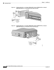
Chapter 2 Installation Installing the Switch Figure 2-6 Attaching Brackets on a Catalyst 2950G-48-EI, Catalyst 2950SX-48-SI, or Catalyst 2950T-48-SI Switch in a 19-Inch Telco Rack CONSOLE 65514 Number-8 Phillips flat-head screws Figure 2-7 Attaching Brackets on the Catalyst 2950G-24-EI-DC or 2950ST-24 LRE 997 Switch in a 23-Inch Telco Rack (Front Panel Forward) Number-8 Phillips truss-head screws SYST RPS STAT UTIL DUPLX SPEED MODE 1 1X 23 45 67 8 9 10 11 12 11X 2X 12X 65673 OL-6156-01 Catalyst 2950 Switch Hardware Installation Guide 2-11
Chapter 2 Installation Installing the Switch Figure 2-6 Attaching Brackets on a Catalyst 2950G-48-EI, Catalyst 2950SX-48-SI, or Catalyst 2950T-48-SI Switch in a 19-Inch Telco Rack CONSOLE 65514 Number-8 Phillips flat-head screws Figure 2-7 Attaching Brackets on the Catalyst 2950G-24-EI-DC or 2950ST-24 LRE 997 Switch in a 23-Inch Telco Rack (Front Panel Forward) Number-8 Phillips truss-head screws SYST RPS STAT UTIL DUPLX SPEED MODE 1 1X 23 45 67 8 9 10 11 12 11X 2X 12X 65673 OL-6156-01 Catalyst 2950 Switch Hardware Installation Guide 2-11

Hardware Installation Guide
Page 58
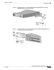
Installing the Switch Chapter 2 Installation Figure 2-8 Attaching Brackets on the Catalyst 2950G-24-EI-DC or 2950ST-24 LRE 997 Switch in a 23-Inch Telco Rack (Rear Panel Forward) CONSOLE 65674 Number-8 Phillips truss-head screws Figure 2-9 Attaching Brackets on the Catalyst 2950G-24-EI-DC or 2950ST-24 LRE 997 Switch in a 23-Inch Telco Rack CONSOLE Number-8 Phillips truss-head screws 65675 2-12 Catalyst 2950 Switch Hardware Installation Guide OL-6156-01
Installing the Switch Chapter 2 Installation Figure 2-8 Attaching Brackets on the Catalyst 2950G-24-EI-DC or 2950ST-24 LRE 997 Switch in a 23-Inch Telco Rack (Rear Panel Forward) CONSOLE 65674 Number-8 Phillips truss-head screws Figure 2-9 Attaching Brackets on the Catalyst 2950G-24-EI-DC or 2950ST-24 LRE 997 Switch in a 23-Inch Telco Rack CONSOLE Number-8 Phillips truss-head screws 65675 2-12 Catalyst 2950 Switch Hardware Installation Guide OL-6156-01