
Service Manual
Page 8
Controlling the Side Blanking Mechanism 4-21 II. Cartridge 4-23 B. PICKUP/FEEDING SYSTEM.......5-1 A. DISASSEMBLY/ASSEMBLY ..... 5-18 A. Single-feeder Assembly ..... 5-31 D. CHAPTER 4 IMAGE FORMATION SYSTEM I . Outline ...5-1 B. Registration Roller Assembly 5-34 F. DISASSEMBLY/ASSEMBLY ..... 6-10 A. Delivery Assembly 5-36 CHAPTER 6 FIXING SYSTEM I . Controlling the Fixing Temperature 6-3 II. CANON PC800s/900s REV.0 AUG. 1999 PRINTED IN JAPAN (IMPRIME AU JAPON) Multifeeder Assembly ......... 5-28 C. Outline 6-1 B. Timing Chart for the Image Formation System ...
Controlling the Side Blanking Mechanism 4-21 II. Cartridge 4-23 B. PICKUP/FEEDING SYSTEM.......5-1 A. DISASSEMBLY/ASSEMBLY ..... 5-18 A. Single-feeder Assembly ..... 5-31 D. CHAPTER 4 IMAGE FORMATION SYSTEM I . Outline ...5-1 B. Registration Roller Assembly 5-34 F. DISASSEMBLY/ASSEMBLY ..... 6-10 A. Delivery Assembly 5-36 CHAPTER 6 FIXING SYSTEM I . Controlling the Fixing Temperature 6-3 II. CANON PC800s/900s REV.0 AUG. 1999 PRINTED IN JAPAN (IMPRIME AU JAPON) Multifeeder Assembly ......... 5-28 C. Outline 6-1 B. Timing Chart for the Image Formation System ...
Service Manual
Page 9
... 8-21 C. CHAPTER 7 EXTERNALS/AUXILIARY MECHANISMS I . Control Panel 7-15 C. Pickup Operation 8-8 F. DISASSEMBLY/ASSEMBLY ..... 8-18 A. Electrical System 8-33 CHAPTER 9 INSTALLATION I . Storing the Cartridge with the Packaging Seal Removed 10-3 COPYRIGHT © 1999 CANON INC. Protecting the Power Supply Circuit 7-6 III. Basic Operations 8-4 D. Removing the ADF 8-19 B. Electrical System 7-21 CHAPTER 8 ADF I . Detecting an Original...
... 8-21 C. CHAPTER 7 EXTERNALS/AUXILIARY MECHANISMS I . Control Panel 7-15 C. Pickup Operation 8-8 F. DISASSEMBLY/ASSEMBLY ..... 8-18 A. Electrical System 8-33 CHAPTER 9 INSTALLATION I . Storing the Cartridge with the Packaging Seal Removed 10-3 COPYRIGHT © 1999 CANON INC. Protecting the Power Supply Circuit 7-6 III. Basic Operations 8-4 D. Removing the ADF 8-19 B. Electrical System 7-21 CHAPTER 8 ADF I . Detecting an Original...
Service Manual
Page 13
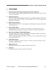
... a roller charging method has resulted in a considerable reduction of paper may contain as many as a single entity (cartridge). COPYRIGHT © 1999 CANON INC. SURF Fixing Assembly • The wait time is possible with existing Canon machines). 3. CANON PC800s/900s REV.0 AUG. 1999 PRINTED IN JAPAN (IMPRIME AU JAPON) 1-1 multifeeder type). 7. All-in 1% increments. 2. Various...
... a roller charging method has resulted in a considerable reduction of paper may contain as many as a single entity (cartridge). COPYRIGHT © 1999 CANON INC. SURF Fixing Assembly • The wait time is possible with existing Canon machines). 3. CANON PC800s/900s REV.0 AUG. 1999 PRINTED IN JAPAN (IMPRIME AU JAPON) 1-1 multifeeder type). 7. All-in 1% increments. 2. Various...
Service Manual
Page 93
... Image Formation System 4-3 C. Controlling the Transfer Roller Bias 4-8 E. Transfer Charging Assembly 4-25 C. DISASSEMBLY/ASSEMBLY ..... 4-22 A. Controlling the Primary Charging Roller Bias 4-4 D. Cartridge 4-23 B. Blank Exposure 4-26 COPYRIGHT © 1999 CANON INC. CANON PC800s/900s REV.0 AUG. 1999 PRINTED IN JAPAN (IMPRIME AU JAPON) Controlling the Side Blanking Mechanism 4-21 II. IMAGE FORMATION SYSTEM...
... Image Formation System 4-3 C. Controlling the Transfer Roller Bias 4-8 E. Transfer Charging Assembly 4-25 C. DISASSEMBLY/ASSEMBLY ..... 4-22 A. Controlling the Primary Charging Roller Bias 4-4 D. Cartridge 4-23 B. Blank Exposure 4-26 COPYRIGHT © 1999 CANON INC. CANON PC800s/900s REV.0 AUG. 1999 PRINTED IN JAPAN (IMPRIME AU JAPON) Controlling the Side Blanking Mechanism 4-21 II. IMAGE FORMATION SYSTEM...
Service Manual
Page 96
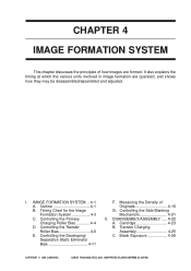
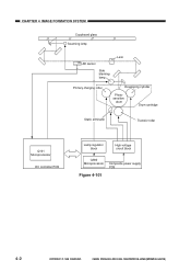
CHAPTER 4 IMAGE FORMATION SYSTEM Copyboard glass Scanning lamp AE sensor Side blanking lamp Lens Primary charging roller Developing cylinder Photosensitive drum Drum cartridge Static eliminator Transfer roller Q101 Microprocessor DC controller PCB Lamp regulator block High-voltage circuit block Q900 Microprocessor Composite power supply PCB Figure 4-101 4-2 COPYRIGHT © 1999 CANON INC. CANON PC800s/900s REV.0 AUG. 1999 PRINTED IN JAPAN (IMPRIME AU JAPON)
CHAPTER 4 IMAGE FORMATION SYSTEM Copyboard glass Scanning lamp AE sensor Side blanking lamp Lens Primary charging roller Developing cylinder Photosensitive drum Drum cartridge Static eliminator Transfer roller Q101 Microprocessor DC controller PCB Lamp regulator block High-voltage circuit block Q900 Microprocessor Composite power supply PCB Figure 4-101 4-2 COPYRIGHT © 1999 CANON INC. CANON PC800s/900s REV.0 AUG. 1999 PRINTED IN JAPAN (IMPRIME AU JAPON)
Service Manual
Page 117
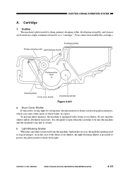
b. COPYRIGHT © 1999 CANON INC. Outline The machine's photosensitive drum, primary charging roller, developing assembly, and cleaner are housed in the case of the drum cover shutter, the light-blocking shutter is designed to as a "cartridge." (You cannot disassemble the cartridge.) Developing blade Primary charging roller Light... develop photo memory, which can cause white spots or black bands on copies. CANON PC800s/900s REV.0 AUG. 1999 PRINTED IN JAPAN (IMPRIME AU JAPON) 4-23 Do not open when the cartridge is fit into the machine and the machine's top unit is closed. Drum...
b. COPYRIGHT © 1999 CANON INC. Outline The machine's photosensitive drum, primary charging roller, developing assembly, and cleaner are housed in the case of the drum cover shutter, the light-blocking shutter is designed to as a "cartridge." (You cannot disassemble the cartridge.) Developing blade Primary charging roller Light... develop photo memory, which can cause white spots or black bands on copies. CANON PC800s/900s REV.0 AUG. 1999 PRINTED IN JAPAN (IMPRIME AU JAPON) 4-23 Do not open when the cartridge is fit into the machine and the machine's top unit is closed. Drum...
Service Manual
Page 118
... If the photosensitive drum is exposed to light of the sun are usually about 10000 to 30000 lux. 4-24 COPYRIGHT © 1999 CANON INC. Be sure to direct sunlight. CANON PC800s/900s REV.0 AUG. 1999 PRINTED IN JAPAN (IMPRIME AU JAPON) Caution: 1. Otherwise, the leaf spring used to apply a ...the Drum Caution: As a rule, do not touch or clean the photosensitive drum. 1) Open the machine's top unit, and take out the cartridge. 2) Turn over the cartridge, and open the drum cover shutter 3) Clean the drum surface with a flannel cloth coated with toner. If you must clean it to work ...
... If the photosensitive drum is exposed to light of the sun are usually about 10000 to 30000 lux. 4-24 COPYRIGHT © 1999 CANON INC. Be sure to direct sunlight. CANON PC800s/900s REV.0 AUG. 1999 PRINTED IN JAPAN (IMPRIME AU JAPON) Caution: 1. Otherwise, the leaf spring used to apply a ...the Drum Caution: As a rule, do not touch or clean the photosensitive drum. 1) Open the machine's top unit, and take out the cartridge. 2) Turn over the cartridge, and open the drum cover shutter 3) Clean the drum surface with a flannel cloth coated with toner. If you must clean it to work ...
Service Manual
Page 120
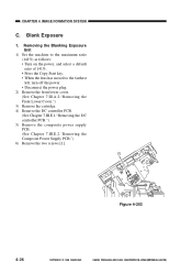
CANON PC800s/900s REV.0 AUG. 1999 PRINTED IN JAPAN (IMPRIME AU JAPON) Blank Exposure 1. Removing the Blanking Exposure Unit 1) Set the machine to the maximum ratio (... left, turn off the power. • Disconnect the power plug. 2) Remove the front lower cover. (See Chapter 7.III.A.2."Removing the Front Lower Cover.") 3) Remove the cartridge. 4) Remove the DC controller PCB. (See Chapter 7.III.E.1."Removing the DC controller PCB.") 5) Remove the composite power supply PCB. (See Chapter 7.III.E.2."Removing the Composite...
CANON PC800s/900s REV.0 AUG. 1999 PRINTED IN JAPAN (IMPRIME AU JAPON) Blank Exposure 1. Removing the Blanking Exposure Unit 1) Set the machine to the maximum ratio (... left, turn off the power. • Disconnect the power plug. 2) Remove the front lower cover. (See Chapter 7.III.A.2."Removing the Front Lower Cover.") 3) Remove the cartridge. 4) Remove the DC controller PCB. (See Chapter 7.III.E.1."Removing the DC controller PCB.") 5) Remove the composite power supply PCB. (See Chapter 7.III.E.2."Removing the Composite...
Service Manual
Page 197
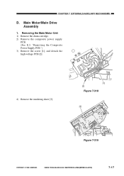
CHAPTER 7 EXTERNALS/AUXILIARY MECHANISMS D. Removing the Main Motor Unit 1) Remove the drum cartridge. 2) Remove the composite power supply PCB. (See E.2. Main Motor/Main Drive Assembly 1. CANON PC800s/900s REV.0 AUG. 1999 PRINTED IN JAPAN (IMPRIME AU JAPON) 7-17 "Removing the Composite Power Supply PCB.") 3) Remove the screw [1], and detach the high-voltage PCB [2]. 4) Remove the insulating sheet [3]. [1] [2] Figure 7-318 [3] Figure 7-319 COPYRIGHT © 1999 CANON INC.
CHAPTER 7 EXTERNALS/AUXILIARY MECHANISMS D. Removing the Main Motor Unit 1) Remove the drum cartridge. 2) Remove the composite power supply PCB. (See E.2. Main Motor/Main Drive Assembly 1. CANON PC800s/900s REV.0 AUG. 1999 PRINTED IN JAPAN (IMPRIME AU JAPON) 7-17 "Removing the Composite Power Supply PCB.") 3) Remove the screw [1], and detach the high-voltage PCB [2]. 4) Remove the insulating sheet [3]. [1] [2] Figure 7-318 [3] Figure 7-319 COPYRIGHT © 1999 CANON INC.
Service Manual
Page 199
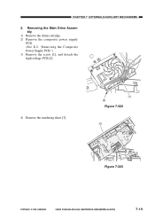
CHAPTER 7 EXTERNALS/AUXILIARY MECHANISMS 2. "Removing the Composite Power Supply PCB.") 3) Remove the screw [1], and detach the high-voltage PCB [2]. 4) Remove the insulating sheet [3]. [1] [2] Figure 7-322 [3] Figure 7-323 COPYRIGHT © 1999 CANON INC. CANON PC800s/900s REV.0 AUG. 1999 PRINTED IN JAPAN (IMPRIME AU JAPON) 7-19 Removing the Main Drive Assembly 1) Remove the drum cartridge. 2) Remove the composite power supply PCB. (See E.2.
CHAPTER 7 EXTERNALS/AUXILIARY MECHANISMS 2. "Removing the Composite Power Supply PCB.") 3) Remove the screw [1], and detach the high-voltage PCB [2]. 4) Remove the insulating sheet [3]. [1] [2] Figure 7-322 [3] Figure 7-323 COPYRIGHT © 1999 CANON INC. CANON PC800s/900s REV.0 AUG. 1999 PRINTED IN JAPAN (IMPRIME AU JAPON) 7-19 Removing the Main Drive Assembly 1) Remove the drum cartridge. 2) Remove the composite power supply PCB. (See E.2.
Service Manual
Page 247
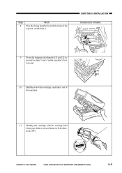
CANON PC800s/900s REV.0 AUG. 1999 PRINTED IN JAPAN (IMPRIME AU JAPON) 9-5 CHAPTER 9 INSTALLATION Checks and remarks 9 Store the shipping attachments [1] and [2] removed in steps 3 and 4 in the machine's bottom unit. [2] [1] 10 Hold the tab of the cartridge, and take it out of the top unit, and detach it several times in both directions (90°). COPYRIGHT © 1999 CANON INC. Step 8 Work Pick the fixing member from the bottom of the machine. 11 Holding the cartridge with the warning label facing up, shake it .
CANON PC800s/900s REV.0 AUG. 1999 PRINTED IN JAPAN (IMPRIME AU JAPON) 9-5 CHAPTER 9 INSTALLATION Checks and remarks 9 Store the shipping attachments [1] and [2] removed in steps 3 and 4 in the machine's bottom unit. [2] [1] 10 Hold the tab of the cartridge, and take it out of the top unit, and detach it several times in both directions (90°). COPYRIGHT © 1999 CANON INC. Step 8 Work Pick the fixing member from the bottom of the machine. 11 Holding the cartridge with the warning label facing up, shake it .
Service Manual
Page 248
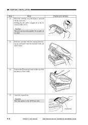
.... Holding the tab, pull it straight out in the middle. Caution: This step applies to close it stops. CANON PC800s/900s REV.0 AUG. 1999 PRINTED IN JAPAN (IMPRIME AU JAPON) Checks and remarks 14 Push on the marking found on a level place, and pull ...off the open seal. Do no pull it at an angle. 13 Hold the cartridge with the waning label facing up, and insert it into the machine with care until it fully. 15 Open the original tray. CHAPTER 9 INSTALLATION Step...
.... Holding the tab, pull it straight out in the middle. Caution: This step applies to close it stops. CANON PC800s/900s REV.0 AUG. 1999 PRINTED IN JAPAN (IMPRIME AU JAPON) Checks and remarks 14 Push on the marking found on a level place, and pull ...off the open seal. Do no pull it at an angle. 13 Hold the cartridge with the waning label facing up, and insert it into the machine with care until it fully. 15 Open the original tray. CHAPTER 9 INSTALLATION Step...
Service Manual
Page 257
SCHEDULED SERVICING ....... 10-1 IV. Storing and Handling the Cartridge with the Packaging Seal Intact ........ 10-2 B. DURABLES AND CONSUMABLES 10-1 III. CANON PC800s/900s REV.0 AUG. 1999 PRINTED IN JAPAN (IMPRIME AU JAPON) CHAPTER 10 MAINTENANCE AND SERVICING I. Storing the Cartridge with the Packaging Seal Removed 10-3 COPYRIGHT © 1999 CANON INC. PERIODICALLY REPLACED PARTS 10-1 II. STORING AND HANDLING THE CARTRIDGE 10-2 A.
SCHEDULED SERVICING ....... 10-1 IV. Storing and Handling the Cartridge with the Packaging Seal Intact ........ 10-2 B. DURABLES AND CONSUMABLES 10-1 III. CANON PC800s/900s REV.0 AUG. 1999 PRINTED IN JAPAN (IMPRIME AU JAPON) CHAPTER 10 MAINTENANCE AND SERVICING I. Storing the Cartridge with the Packaging Seal Removed 10-3 COPYRIGHT © 1999 CANON INC. PERIODICALLY REPLACED PARTS 10-1 II. STORING AND HANDLING THE CARTRIDGE 10-2 A.
Service Manual
Page 259
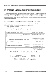
... in addition, keep the following in mind: • Avoid direct rays of copies made. CANON PC800s/900s REV.0 AUG. 1999 PRINTED IN JAPAN (IMPRIME AU JAPON) STORING AND HANDLING THE CARTRIDGE The cartridge is subject to the effects of the environment whether its packing seal is intact or removed or... between -20°C/-4°F and 40°C/104°F Humidity 90% or less Table 10-402 Conditions for Transportation 10-2 COPYRIGHT © 1999 CANON INC. however, it is inside the machine or otherwise, changing over time regardless of the number of the sun. • Avoid vibration. •...
... in addition, keep the following in mind: • Avoid direct rays of copies made. CANON PC800s/900s REV.0 AUG. 1999 PRINTED IN JAPAN (IMPRIME AU JAPON) STORING AND HANDLING THE CARTRIDGE The cartridge is subject to the effects of the environment whether its packing seal is intact or removed or... between -20°C/-4°F and 40°C/104°F Humidity 90% or less Table 10-402 Conditions for Transportation 10-2 COPYRIGHT © 1999 CANON INC. however, it is inside the machine or otherwise, changing over time regardless of the number of the sun. • Avoid vibration. •...
Service Manual
Page 260
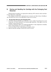
...it in an appropriate storage box for storage.) 1. COPYRIGHT © 1999 CANON INC. Avoid areas subject to change abruptly (e.g., near a window. CHAPTER 10 MAINTENANCE AND SERVICING B. Do not keep it . (Be sure that the cartridge is inside a protective box.) b. Storage after Removing the Packaging Seal ... extremely high temperature. (This applies even if the cartridge is stored at 40°C/104°F or lower. CANON PC800s/900s REV.0 AUG. 1999 PRINTED IN JAPAN (IMPRIME AU JAPON) 10-3 Storing and Handling the Cartridge with the Packaging Seal Removed The photosensitive medium is ...
...it in an appropriate storage box for storage.) 1. COPYRIGHT © 1999 CANON INC. Avoid areas subject to change abruptly (e.g., near a window. CHAPTER 10 MAINTENANCE AND SERVICING B. Do not keep it . (Be sure that the cartridge is inside a protective box.) b. Storage after Removing the Packaging Seal ... extremely high temperature. (This applies even if the cartridge is stored at 40°C/104°F or lower. CANON PC800s/900s REV.0 AUG. 1999 PRINTED IN JAPAN (IMPRIME AU JAPON) 10-3 Storing and Handling the Cartridge with the Packaging Seal Removed The photosensitive medium is ...
Service Manual
Page 261
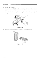
... it starts to even out the toner inside. Figure 10-402 10-4 COPYRIGHT © 1999 CANON INC. If you shake it about 90° several times as shown in Figure 10-402. Do not place the cartridge on its end or turn it over as shown in a different way, the toner can... spill out of toner, hold the cartridge level and shake it in Figure 10401 to run out of the developing assembly or the cleaning assembly. CANON PC800s/900s REV.0 AUG. 1999 PRINTED IN JAPAN (IMPRIME AU JAPON) CHAPTER 10 MAINTENANCE AND SERVICING...
... it starts to even out the toner inside. Figure 10-402 10-4 COPYRIGHT © 1999 CANON INC. If you shake it about 90° several times as shown in Figure 10-402. Do not place the cartridge on its end or turn it over as shown in a different way, the toner can... spill out of toner, hold the cartridge level and shake it in Figure 10401 to run out of the developing assembly or the cleaning assembly. CANON PC800s/900s REV.0 AUG. 1999 PRINTED IN JAPAN (IMPRIME AU JAPON) CHAPTER 10 MAINTENANCE AND SERVICING...
Service Manual
Page 262
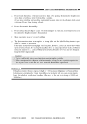
...machine alone as long as 10000 and 30000 lux.) COPYRIGHT © 1999 CANON INC. In particular, do not impose force on the shutter for storage, be sure to show white spots or vertical bands. g. If the cartridge must be taken out of protection. Keep the following in a protective ...long time, however, copies can start to put it in mind: Caution: 1. CANON PC800s/900s REV.0 AUG. 1999 PRINTED IN JAPAN (IMPRIME AU JAPON) 10-5 Do not subject the cartridge to work briskly when removing a jam or replacing the cartridge. 2. Do not leave it using solvents.) d. If the drum is noted;...
...machine alone as long as 10000 and 30000 lux.) COPYRIGHT © 1999 CANON INC. In particular, do not impose force on the shutter for storage, be sure to show white spots or vertical bands. g. If the cartridge must be taken out of protection. Keep the following in a protective ...long time, however, copies can start to put it in mind: Caution: 1. CANON PC800s/900s REV.0 AUG. 1999 PRINTED IN JAPAN (IMPRIME AU JAPON) 10-5 Do not subject the cartridge to work briskly when removing a jam or replacing the cartridge. 2. Do not leave it using solvents.) d. If the drum is noted;...
Service Manual
Page 268
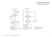
...middle index? (Note 1) Set it at the middle. Density of background (Note 2) I. Cartridge 2. Scanning lamp 3. Composite power supply PCB (See the appropriate troubleshooting procedure.) END Note: 1. CANON PC800s/900s REV.0 AUG. 1999 PRINTED IN JAPAN (IMPRIME AU JAPON) 11-3 Making Pre-...AE sensor PCB 4. Applies only if the machine is not equipped with a copy density correction switch (SW101). 2. COPYRIGHT © 1999 CANON INC. The machine is equipped with a function to the middle index; See the appropriate troubleshooting procedure. 3. See p. 11-42. ...
...middle index? (Note 1) Set it at the middle. Density of background (Note 2) I. Cartridge 2. Scanning lamp 3. Composite power supply PCB (See the appropriate troubleshooting procedure.) END Note: 1. CANON PC800s/900s REV.0 AUG. 1999 PRINTED IN JAPAN (IMPRIME AU JAPON) 11-3 Making Pre-...AE sensor PCB 4. Applies only if the machine is not equipped with a copy density correction switch (SW101). 2. COPYRIGHT © 1999 CANON INC. The machine is equipped with a function to the middle index; See the appropriate troubleshooting procedure. 3. See p. 11-42. ...
Service Manual
Page 269
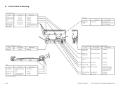
...sure to remove all toner to touch it well. Take care not to prevent toner soiling images. COPYRIGHT © 1999 CANON INC. Points to wring it or leave solvent or oil. ADF Item Tool/solvent Feeding belt Cloth moistened with water* ...-free paper roller Static eliminator Feed belt Special brush Moist cloth Cleaning. Cleaning. Cleaning. Cleaning. Cleaning. Dry wiping. Cleaning. 11-4 Cartridge Item Drum cover shutter Tools/solvents Most cloth Work/remarks Cleaning; B. Cleaning. Cleaning. Cleaning. Fixing Assembly, Delivery Assembly Item Tools/solvent...
...sure to remove all toner to touch it well. Take care not to prevent toner soiling images. COPYRIGHT © 1999 CANON INC. Points to wring it or leave solvent or oil. ADF Item Tool/solvent Feeding belt Cloth moistened with water* ...-free paper roller Static eliminator Feed belt Special brush Moist cloth Cleaning. Cleaning. Cleaning. Cleaning. Cleaning. Dry wiping. Cleaning. 11-4 Cartridge Item Drum cover shutter Tools/solvents Most cloth Work/remarks Cleaning; B. Cleaning. Cleaning. Cleaning. Fixing Assembly, Delivery Assembly Item Tools/solvent...
Service Manual
Page 307
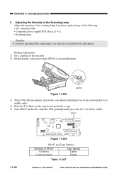
... lamp if you have replaced any of VR107 Clockwise Counterclockwise Copy density Lighter Darker Table 11-207 11-42 COPYRIGHT © 1999 CANON INC. SW101 Figure 11-263 3) Turn off the AE mechanism, and set the copy density adjusting lever on the control panel ...copy. 5) Turn VR107 on the DC controller PCB gradually until gray scale No. 9 is barely visible. CANON PC800s/900s REV.0 AUG. 1999 PRINTED IN JAPAN (IMPRIME AU JAPON) CHAPTER 11 TROUBLESHOOTING 2. Making Adjustments 1) Set a cartridge in the machine. 2) Set the density correction switch (SW101) to its middle index.
... lamp if you have replaced any of VR107 Clockwise Counterclockwise Copy density Lighter Darker Table 11-207 11-42 COPYRIGHT © 1999 CANON INC. SW101 Figure 11-263 3) Turn off the AE mechanism, and set the copy density adjusting lever on the control panel ...copy. 5) Turn VR107 on the DC controller PCB gradually until gray scale No. 9 is barely visible. CANON PC800s/900s REV.0 AUG. 1999 PRINTED IN JAPAN (IMPRIME AU JAPON) CHAPTER 11 TROUBLESHOOTING 2. Making Adjustments 1) Set a cartridge in the machine. 2) Set the density correction switch (SW101) to its middle index.


