
Service Manual
Page 9
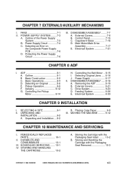
Detecting an Error on the Composite Power Supply PCB 7-6 D. ADF 8-1 A. Pickup Operation 8-8 F. UNPACKING AND INSTALLATION 9-2 A. Placing Copy Paper 9-9 III. DURABLES AND CONSUMABLES 10-1 III. Storing the Cartridge with the Packaging Seal Removed 10-3 COPYRIGHT © 1999 CANON INC. External Covers 7-8 B. Control Panel 7-15 C. Feeding System 8-26 E. Unpacking and Installation ....9-2 B. STORING AND HANDLING THE...
Detecting an Error on the Composite Power Supply PCB 7-6 D. ADF 8-1 A. Pickup Operation 8-8 F. UNPACKING AND INSTALLATION 9-2 A. Placing Copy Paper 9-9 III. DURABLES AND CONSUMABLES 10-1 III. Storing the Cartridge with the Packaging Seal Removed 10-3 COPYRIGHT © 1999 CANON INC. External Covers 7-8 B. Control Panel 7-15 C. Feeding System 8-26 E. Unpacking and Installation ....9-2 B. STORING AND HANDLING THE...
Service Manual
Page 29
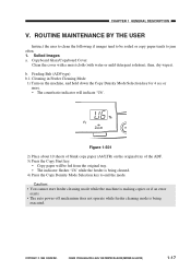
...jam often. 1. then, dry wipe it. Soiled Images a. b. Caution: • You cannot start feeder cleaning mode while the machine is making copies or if an error exists. • The auto power-off mechanism does not operate while feeder cleaning mode is being cleaned. 4) Press the Copy Density Mode Selection key to... be fed from the original tray. • The indicator flashes 'U6' while the feeder is being executed. COPYRIGHT © 1999 CANON INC. ROUTINE MAINTENANCE BY THE USER Instruct the user to clean the following if images tend to end the mode.
...jam often. 1. then, dry wipe it. Soiled Images a. b. Caution: • You cannot start feeder cleaning mode while the machine is making copies or if an error exists. • The auto power-off mechanism does not operate while feeder cleaning mode is being cleaned. 4) Press the Copy Density Mode Selection key to... be fed from the original tray. • The indicator flashes 'U6' while the feeder is being executed. COPYRIGHT © 1999 CANON INC. ROUTINE MAINTENANCE BY THE USER Instruct the user to clean the following if images tend to end the mode.
Service Manual
Page 41
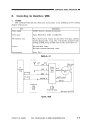
... Hall IC output MMCLK Composite power supply PCB Reference signal Main motor drive PCB Figure 2-104 COPYRIGHT © 1999 CANON INC. Controlling the Main Motor (M1) 1. CANON PC800s/900s REV.0 AUG. 1999 PRINTED IN JAPAN (IMPRIME AU JAPON) 2-5 Drive signal Signal (MMD) from the... composite power supply. CHAPTER 2 BASIC OPERATION D. Error detection Issues 'E010'. Outline Table 2-102 shows the functions of the main motor control...
... Hall IC output MMCLK Composite power supply PCB Reference signal Main motor drive PCB Figure 2-104 COPYRIGHT © 1999 CANON INC. Controlling the Main Motor (M1) 1. CANON PC800s/900s REV.0 AUG. 1999 PRINTED IN JAPAN (IMPRIME AU JAPON) 2-5 Drive signal Signal (MMD) from the... composite power supply. CHAPTER 2 BASIC OPERATION D. Error detection Issues 'E010'. Outline Table 2-102 shows the functions of the main motor control...
Service Manual
Page 42
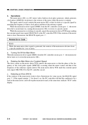
...these clock pulses and that of the frequency of the main motor starts to rotate the main motor (M1). CANON PC800s/900s REV.0 AUG. 1999 PRINTED IN JAPAN (IMPRIME AU JAPON) Detecting an Error (E010) If the rotation of the reference signals match. a. Turning On/Off the Main Motor When the ...so that it rotates at a specific speed. The main motor driver PCB sends the constant speed state signal (MLOCK=0) to the DC controller PCB. Related Error Code E010 While the main motor drive signal is rotating at the same time, indicate 'E010' in the main motor, and will stop the main...
...these clock pulses and that of the frequency of the main motor starts to rotate the main motor (M1). CANON PC800s/900s REV.0 AUG. 1999 PRINTED IN JAPAN (IMPRIME AU JAPON) Detecting an Error (E010) If the rotation of the reference signals match. a. Turning On/Off the Main Motor When the ...so that it rotates at a specific speed. The main motor driver PCB sends the constant speed state signal (MLOCK=0) to the DC controller PCB. Related Error Code E010 While the main motor drive signal is rotating at the same time, indicate 'E010' in the main motor, and will stop the main...
Service Manual
Page 61
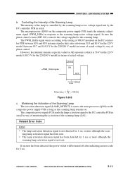
... the intensity adjust- t [msec] ON OFF 1 [msec] 1kHz 1 Pulse duty= t/ 1k × 100 [%] Figure 3-202 c. COPYRIGHT © 1999 CANON INC. The PWM_1KHz signal varies according to the setting of actual voltage. The composite power supply PCB sends the lamp activation signal to the scanning...Q900) on the composite power supply PCB as long as the scanning lamp remains on. CANON PC800s/900s REV.0 AUG. 1999 PRINTED IN JAPAN (IMPRIME AU JAPON) 3-11 CHAPTER 3 EXPOSURE SYSTEM b. Related Error Code E220 • The lamp activation detection signal is not detected for 2 sec. ...
... the intensity adjust- t [msec] ON OFF 1 [msec] 1kHz 1 Pulse duty= t/ 1k × 100 [%] Figure 3-202 c. COPYRIGHT © 1999 CANON INC. The PWM_1KHz signal varies according to the setting of actual voltage. The composite power supply PCB sends the lamp activation signal to the scanning...Q900) on the composite power supply PCB as long as the scanning lamp remains on. CANON PC800s/900s REV.0 AUG. 1999 PRINTED IN JAPAN (IMPRIME AU JAPON) 3-11 CHAPTER 3 EXPOSURE SYSTEM b. Related Error Code E220 • The lamp activation detection signal is not detected for 2 sec. ...
Service Manual
Page 165
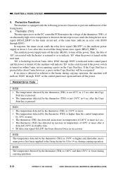
...detected overheating. activating at 228°C) Error code E000 E001 E002 E003 The fixing temperature fails to the fixing heater will be cut: • Thermistor (TH1) • Thermal fuse (FU2; The fixing temperature has dropped abnormally. Table 6-101 COPYRIGHT © 1999 CANON INC. CANON PC800s/900s REV.0 AUG. 1999 PRINTED... Flat heater Fixing temperature Thermistor (TH1) detection Cleaner Cleaning roller Protective functions The following are used to detect and protect against an error; Fault in fixing power control. CHAPTER 6 FIXING SYSTEM I. OPERATIONS A.
...detected overheating. activating at 228°C) Error code E000 E001 E002 E003 The fixing temperature fails to the fixing heater will be cut: • Thermistor (TH1) • Thermal fuse (FU2; The fixing temperature has dropped abnormally. Table 6-101 COPYRIGHT © 1999 CANON INC. CANON PC800s/900s REV.0 AUG. 1999 PRINTED... Flat heater Fixing temperature Thermistor (TH1) detection Cleaner Cleaning roller Protective functions The following are used to detect and protect against an error; Fault in fixing power control. CHAPTER 6 FIXING SYSTEM I. OPERATIONS A.

Service Manual
Page 167
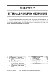
... (HEAT_PWM) to vary the power supplied to the microprocessor (Q101) on the DC controller PCB; in conjunction. CHAPTER 6 FIXING SYSTEM B. CANON PC800s/900s REV.0 AUG. 1999 PRINTED IN JAPAN (IMPRIME AU JAPON) 6-3 The fixing heater is equipped with a thermistor (TH1), which ...5V (Q101) Thermal fuse 2 FU2 Fixing thermistor TH1 Fixing heater H1 Timer circuit Fixing heater high temperature error detection circuit HEAT_ERR* Fixing heater error signal MicroHEAT_OFF processor Fixing heater OFF signal HEAT_PWM Fixing heater duty signal HEAT_TRG Fixing heater drive signal Composite power...
... (HEAT_PWM) to vary the power supplied to the microprocessor (Q101) on the DC controller PCB; in conjunction. CHAPTER 6 FIXING SYSTEM B. CANON PC800s/900s REV.0 AUG. 1999 PRINTED IN JAPAN (IMPRIME AU JAPON) 6-3 The fixing heater is equipped with a thermistor (TH1), which ...5V (Q101) Thermal fuse 2 FU2 Fixing thermistor TH1 Fixing heater H1 Timer circuit Fixing heater high temperature error detection circuit HEAT_ERR* Fixing heater error signal MicroHEAT_OFF processor Fixing heater OFF signal HEAT_PWM Fixing heater duty signal HEAT_TRG Fixing heater drive signal Composite power...
Service Manual
Page 172
Thermistor (TH1) The microprocessor on the Copy Start key. If an error is detected in relation to the heater during copying operation. 6-8 COPYRIGHT © 1999 CANON INC. Protective Functions The machine is equipped with the heater) is higher than the control temperature by 30°C or ... and, thereafter, maximum power has been supplied to the fixing heater for about 1.2 sec after it hs received the fixing heater error signal (HEAT_ERR*). CANON PC800s/900s REV.0 AUG. 1999 PRINTED IN JAPAN (IMPRIME AU JAPON) a. The auxiliary power supply turns off the power. E002...
Thermistor (TH1) The microprocessor on the Copy Start key. If an error is detected in relation to the heater during copying operation. 6-8 COPYRIGHT © 1999 CANON INC. Protective Functions The machine is equipped with the heater) is higher than the control temperature by 30°C or ... and, thereafter, maximum power has been supplied to the fixing heater for about 1.2 sec after it hs received the fixing heater error signal (HEAT_ERR*). CANON PC800s/900s REV.0 AUG. 1999 PRINTED IN JAPAN (IMPRIME AU JAPON) a. The auxiliary power supply turns off the power. E002...
Service Manual
Page 179
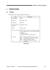
Main Motor/Main Drive Assembly 7-17 E. Electrical System 7-21 COPYRIGHT © 1999 CANON INC. CANON PC800s/900s REV.0 AUG. 1999 PRINTED IN JAPAN (IMPRIME AU JAPON) It also shows how these units may be disassembled/assembled and... adjusted. POWER SUPPLY SYSTEM .........7-3 A. Protecting the Power Supply Circuit 7-6 III. I. FANS 7-1 II. Control Panel 7-15 C. Copyboard Glass 7-16 D. Detecting an Error on the Composite Power Supply PCB...
Main Motor/Main Drive Assembly 7-17 E. Electrical System 7-21 COPYRIGHT © 1999 CANON INC. CANON PC800s/900s REV.0 AUG. 1999 PRINTED IN JAPAN (IMPRIME AU JAPON) It also shows how these units may be disassembled/assembled and... adjusted. POWER SUPPLY SYSTEM .........7-3 A. Protecting the Power Supply Circuit 7-6 III. I. FANS 7-1 II. Control Panel 7-15 C. Copyboard Glass 7-16 D. Detecting an Error on the Composite Power Supply PCB...
Service Manual
Page 184
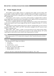
... used : • During copying, +24 V ±5% • During standby, +18 V ±10% However, the above assume that an error related to indicate that the deviations in which a DC power supply, scanning lamp power supply, and high-voltage power supply are used to the DC... the power switch is turned off , the power to operate the switch. When the power switch is equipped with the machine's DC controller PCB. CANON PC800s/900s REV.0 AUG. 1999 PRINTED IN JAPAN (IMPRIME AU JAPON) CHAPTER 7 EXTERNALS/AUXILIARY MECHANISMS B. The auxiliary power supply provides the microprocessor (...
... used : • During copying, +24 V ±5% • During standby, +18 V ±10% However, the above assume that an error related to indicate that the deviations in which a DC power supply, scanning lamp power supply, and high-voltage power supply are used to the DC... the power switch is turned off , the power to operate the switch. When the power switch is equipped with the machine's DC controller PCB. CANON PC800s/900s REV.0 AUG. 1999 PRINTED IN JAPAN (IMPRIME AU JAPON) CHAPTER 7 EXTERNALS/AUXILIARY MECHANISMS B. The auxiliary power supply provides the microprocessor (...
Service Manual
Page 186
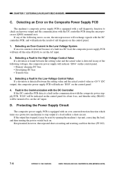
...in mind, however, that repeated short-circuiting and resetting can blow the fuse (FU102). 7-6 COPYRIGHT © 1999 CANON INC. Detecting a Fault in any of the following errors occurs, the microprocessor will exchange signals with the DC controller PCB using the microprocessor (Q900) mounted on a protective mechanism... to cut the AC input. Detecting an Error on the Composite Power Supply PCB The machine's composite power supply PCB is detected between the setting value and the actual value ...
...in mind, however, that repeated short-circuiting and resetting can blow the fuse (FU102). 7-6 COPYRIGHT © 1999 CANON INC. Detecting a Fault in any of the following errors occurs, the microprocessor will exchange signals with the DC controller PCB using the microprocessor (Q900) mounted on a protective mechanism... to cut the AC input. Detecting an Error on the Composite Power Supply PCB The machine's composite power supply PCB is detected between the setting value and the actual value ...
Service Manual
Page 326
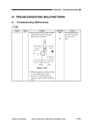
...NO YES NO Action See the instructions given for the respective error code. COPYRIGHT © 1999 CANON INC. JP102 JP101 JP102 JP101 Figure 11-401 2) While keeping the condition in step 1), turn on the power switch. 3) Is an error code indicated in response to a press on the DC controller... PCB with a screwdriver. Troubleshooting Malfunctions 1 E0 Cause Step 1 Checks 1) Turn off the power, and short JP101 and JP102 on the Copy Start key? CANON PC800s/900s REV.0 AUG. 1999 PRINTED ...
...NO YES NO Action See the instructions given for the respective error code. COPYRIGHT © 1999 CANON INC. JP102 JP101 JP102 JP101 Figure 11-401 2) While keeping the condition in step 1), turn on the power switch. 3) Is an error code indicated in response to a press on the DC controller... PCB with a screwdriver. Troubleshooting Malfunctions 1 E0 Cause Step 1 Checks 1) Turn off the power, and short JP101 and JP102 on the Copy Start key? CANON PC800s/900s REV.0 AUG. 1999 PRINTED ...
Service Manual
Page 351
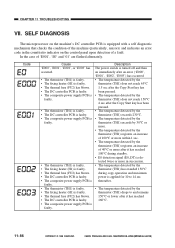
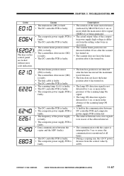
...more in succession. • The temperature detected by the thermistor (TH1) has exeeded 150°C during copy operation and maximum power is faulty. CANON PC800s/900s REV.0 AUG. 1999 PRINTED IN JAPAN (IMPRIME AU JAPON) CHAPTER 11 TROUBLESHOOTING VII. Code Cause 'E000', 'E001', 'E002', or... is equipped with a self diagnostic mechanism that checks the condition of the machine (particularly, sensors) and indicates an error code in the count/ratio indicator on immediately after an error ('E000', 'E001', 'E002', 'E003') has occurred. • The temperature detected by the thermistor (TH1) does...
...more in succession. • The temperature detected by the thermistor (TH1) has exeeded 150°C during copy operation and maximum power is faulty. CANON PC800s/900s REV.0 AUG. 1999 PRINTED IN JAPAN (IMPRIME AU JAPON) CHAPTER 11 TROUBLESHOOTING VII. Code Cause 'E000', 'E001', 'E002', or... is equipped with a self diagnostic mechanism that checks the condition of the machine (particularly, sensors) and indicates an error code in the count/ratio indicator on immediately after an error ('E000', 'E001', 'E002', 'E003') has occurred. • The temperature detected by the thermistor (TH1) does...
Service Manual
Page 352
the communication is faulty. CANON PC800s/900s REV.0 AUG. 1999 PRINTED IN JAPAN (IMPRIME AU JAPON) 11-87 without error code indication. Description • The rotation of the main motor deviates (indicated by MLOCK=0) for 1 sec or more while the main motor drive signal (MMD=1) ... are locked • The scanner/lens drive motor (M2) is faulty. • The DC controller PCB is interrupted for 5 sec or more; COPYRIGHT © 1999 CANON INC. The keys on . • The lamp ON detection signal is not detected for 1 sec or more in the presence of the scanning lamp On...
the communication is faulty. CANON PC800s/900s REV.0 AUG. 1999 PRINTED IN JAPAN (IMPRIME AU JAPON) 11-87 without error code indication. Description • The rotation of the main motor deviates (indicated by MLOCK=0) for 1 sec or more while the main motor drive signal (MMD=1) ... are locked • The scanner/lens drive motor (M2) is faulty. • The DC controller PCB is interrupted for 5 sec or more; COPYRIGHT © 1999 CANON INC. The keys on . • The lamp ON detection signal is not detected for 1 sec or more in the presence of the scanning lamp On...
Service Manual
Page 358
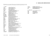
...AER AE (MEASUREMENT) ROTATION INTR INITIAL ROTATION LSTR LAST ROTATION SCFW SCANNER FORWARD SCRV SCANNER REVERSE STBY STANDBY COPYRIGHT © 1999 CANON INC. Signals ACBIAS [AE] AEREF BIAS_PWM BIAS_S CLK32K CPUSD DPD DV_AC_ON DV_DC_ON E0_DT FM1D HEAT_ERR HEAT_OFF HEAT_PWM HEAT_TRG LAMP_DETECT LAMP_ON LHP LNSLD... DEVELOPING AC BIAS ON signal DEVELOPING DC BIAS ON signal E0 DETECTION signal SCANNER COOLING FAN DRIVE signal FIXING HEATER ERROR signal FIXING HEATER OFF signal FIXING HEATER DUTY signal FIXING HEATER DRIVE signal LAMP ACTIVATION DETECTION signal SCANNING LAMP ACTIVATION ...
...AER AE (MEASUREMENT) ROTATION INTR INITIAL ROTATION LSTR LAST ROTATION SCFW SCANNER FORWARD SCRV SCANNER REVERSE STBY STANDBY COPYRIGHT © 1999 CANON INC. Signals ACBIAS [AE] AEREF BIAS_PWM BIAS_S CLK32K CPUSD DPD DV_AC_ON DV_DC_ON E0_DT FM1D HEAT_ERR HEAT_OFF HEAT_PWM HEAT_TRG LAMP_DETECT LAMP_ON LHP LNSLD... DEVELOPING AC BIAS ON signal DEVELOPING DC BIAS ON signal E0 DETECTION signal SCANNER COOLING FAN DRIVE signal FIXING HEATER ERROR signal FIXING HEATER OFF signal FIXING HEATER DUTY signal FIXING HEATER DRIVE signal LAMP ACTIVATION DETECTION signal SCANNING LAMP ACTIVATION ...


