
Service Manual
Page 10
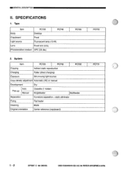
CANON PC720/740/7501770 REV.0 AUG.1994 PRINTED IN JAPAN EMPRIME AU JAPON) Type Item PC720 PC740 Body Desktop Copyboard Fixed Light source Fluorescent lamp (19 W) Lens Fixed lens array Photosensitive medium OPC (24 dia.) PC750 2. System Item PC720 PC740 PC750 Copying Indirect static reproduction Charging Roller (direct charging)... Curvature separation + static eliminator Fixing Flat heater Cleaning Blade Original orientation Center reference (copyboard) PC770 PC770 1 - 2 COPYRIGHT © 1994 CANON INC. =GENERAL DESCRIPTION II. SPECIFICATIONS 1.
CANON PC720/740/7501770 REV.0 AUG.1994 PRINTED IN JAPAN EMPRIME AU JAPON) Type Item PC720 PC740 Body Desktop Copyboard Fixed Light source Fluorescent lamp (19 W) Lens Fixed lens array Photosensitive medium OPC (24 dia.) PC750 2. System Item PC720 PC740 PC750 Copying Indirect static reproduction Charging Roller (direct charging)... Curvature separation + static eliminator Fixing Flat heater Cleaning Blade Original orientation Center reference (copyboard) PC770 PC770 1 - 2 COPYRIGHT © 1994 CANON INC. =GENERAL DESCRIPTION II. SPECIFICATIONS 1.

Service Manual
Page 17
CANON PC720/7401750/770 REV.O AUG.1994 PRINTED IN JAPAN EMPRIME AU JAPON) 1- 9 Selects a default reproduction ratio. Selects or deselects AE mode. GENERAL DESCRIPTIONNM Ref. Selects or deselects zoom mode. May be between 70% and 141% in 1% increments. Name 11 Copy Count/ Zoom Set key 12 Paper Select key 13 Zoom Mode key 14 Default Ratio key 15 AE key Description Sets a copy count or a reproduction ratio. Remarks Selects the cassette as the source of paper or Selects the multifeeder. Table 1-401b COPYRIGHT 1994 CANON INC.
CANON PC720/7401750/770 REV.O AUG.1994 PRINTED IN JAPAN EMPRIME AU JAPON) 1- 9 Selects a default reproduction ratio. Selects or deselects AE mode. GENERAL DESCRIPTIONNM Ref. Selects or deselects zoom mode. May be between 70% and 141% in 1% increments. Name 11 Copy Count/ Zoom Set key 12 Paper Select key 13 Zoom Mode key 14 Default Ratio key 15 AE key Description Sets a copy count or a reproduction ratio. Remarks Selects the cassette as the source of paper or Selects the multifeeder. Table 1-401b COPYRIGHT 1994 CANON INC.

Service Manual
Page 23
... back in the cassette. 2) If the cassette is out of the multifeeder. 2) Open the right cover, and check if there is properly set in . CANON PC720/T401759/770 REV.O AUG.1994 PRINTEDIN JAPANRout AU JAPONI 1 - 15 Remove the paper if found. 3) Shift the open/close lever to the following : C)..., and the copier will make the remaining number of paper from inside the machine. 0 Remove the jam with care. 0 Figure 1-411 COPYRIGHT 1994 CANON INC. CI The 'P' indication should go through the following conditions: C) When the cassette has run out of paper. 02 When the Copy Start key...
... back in the cassette. 2) If the cassette is out of the multifeeder. 2) Open the right cover, and check if there is properly set in . CANON PC720/T401759/770 REV.O AUG.1994 PRINTEDIN JAPANRout AU JAPONI 1 - 15 Remove the paper if found. 3) Shift the open/close lever to the following : C)..., and the copier will make the remaining number of paper from inside the machine. 0 Remove the jam with care. 0 Figure 1-411 COPYRIGHT 1994 CANON INC. CI The 'P' indication should go through the following conditions: C) When the cassette has run out of paper. 02 When the Copy Start key...
Service Manual
Page 26
... it well. Lighte Darker Figure 1-420 Caution: Do not make copies until the cassette pick-up roller Separation pad Figure 1-421 1 - 18 COPYRIGHT © 1994 CANON INC. O G. CANON PC720/7408EORT0 REVS AUG. 1994 PRINTED IN JAPAN tIMPRIME AU JAPONI
... it well. Lighte Darker Figure 1-420 Caution: Do not make copies until the cassette pick-up roller Separation pad Figure 1-421 1 - 18 COPYRIGHT © 1994 CANON INC. O G. CANON PC720/7408EORT0 REVS AUG. 1994 PRINTED IN JAPAN tIMPRIME AU JAPONI
Service Manual
Page 33
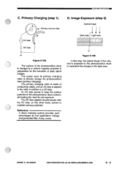
... the photosensitive drum is applied to the roller in addition to a uniform negative potential in the light area. CANON PC720/740/150M0 REV.O AUG.1994 PRINTED IN JAPAN pmplatt AU JAPON) 2 - 3 COPYRIGHT © 1994 CANON INC. Primary Charging (step 1) A-Primary corona roller ti AC bias DC bias D. Reference: A direct charging system provides such...
... the photosensitive drum is applied to the roller in addition to a uniform negative potential in the light area. CANON PC720/740/150M0 REV.O AUG.1994 PRINTED IN JAPAN pmplatt AU JAPON) 2 - 3 COPYRIGHT © 1994 CANON INC. Primary Charging (step 1) A-Primary corona roller ti AC bias DC bias D. Reference: A direct charging system provides such...
Service Manual
Page 36
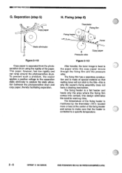
Fixing (step 6) Copy paper O Fixing heater Thermistor Fixing film Toner Static eliminator Figure 2-112 Copy paper is fixed to a specific temperature. 2 - 6 COPYRIGHT © 1994 CANON INC. Pressure roller Copy paper Figure 2-113 After transfer, the toner image is separated from the photosensitive drum using the rigidity of special material so ... film-this design eliminates the need for warm-up time. Separation (step 5) H. Thin paper, however, has low rigidity and can wrap around the photosensitive drum. CANON PC720,740/750i770 REY.0 AUG.1994 PRINTEDIN JAPAN DIARIME AU JAPON)
Fixing (step 6) Copy paper O Fixing heater Thermistor Fixing film Toner Static eliminator Figure 2-112 Copy paper is fixed to a specific temperature. 2 - 6 COPYRIGHT © 1994 CANON INC. Pressure roller Copy paper Figure 2-113 After transfer, the toner image is separated from the photosensitive drum using the rigidity of special material so ... film-this design eliminates the need for warm-up time. Separation (step 5) H. Thin paper, however, has low rigidity and can wrap around the photosensitive drum. CANON PC720,740/750i770 REY.0 AUG.1994 PRINTEDIN JAPAN DIARIME AU JAPON)

Service Manual
Page 38
AUXILIARY PROCESS 1. CANON PC720/74017501770 REV.O AUG.1994 PAINTED IN JAPAN omPRimt AU JAPON) Side Blank Exposure Side blank exposure is used to prevent adhesion of excess toner to the drum by removing the residual potential in the nonimage areas of the drum. See p. 3-35 for details. 2 - 8 COPYRIGHT © 1994 CANON INC. IIIIIII COPYING PROCESS II.
AUXILIARY PROCESS 1. CANON PC720/74017501770 REV.O AUG.1994 PAINTED IN JAPAN omPRimt AU JAPON) Side Blank Exposure Side blank exposure is used to prevent adhesion of excess toner to the drum by removing the residual potential in the nonimage areas of the drum. See p. 3-35 for details. 2 - 8 COPYRIGHT © 1994 CANON INC. IIIIIII COPYING PROCESS II.

Service Manual
Page 46
...SC_B* SC_B during operation, SC_COMA alternates between '0' and '1'. Side blank exposure lamp (front) '+24V *Negative logic. 3 - 6 Figure 3-106 COPYRIGHT © 1994 CANON INC. Outputs from the DC Controller (2/2) DC controller PCB Pick-up clutch solenoid SL1 Registration clutch solenoid SL2 Lens drive solenoid SL3 Cassette/Multifeeder pick-...when '0', registration clutch t +24V solenoid turns on . ®OPERATIONS AND TIMING 2. J109-1 -2 LNSLD* t +24V when '0', lens drive solenoid turns on . CANON PC720/74017501170 REVD AUG.1994 PAINTEDIN JAPAN EMPRIMEAU JAPON)
...SC_B* SC_B during operation, SC_COMA alternates between '0' and '1'. Side blank exposure lamp (front) '+24V *Negative logic. 3 - 6 Figure 3-106 COPYRIGHT © 1994 CANON INC. Outputs from the DC Controller (2/2) DC controller PCB Pick-up clutch solenoid SL1 Registration clutch solenoid SL2 Lens drive solenoid SL3 Cassette/Multifeeder pick-...when '0', registration clutch t +24V solenoid turns on . ®OPERATIONS AND TIMING 2. J109-1 -2 LNSLD* t +24V when '0', lens drive solenoid turns on . CANON PC720/74017501170 REVD AUG.1994 PAINTEDIN JAPAN EMPRIMEAU JAPON)
Service Manual
Page 61
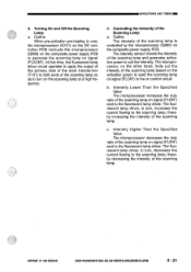
... on the composite power supply PCB. Intensity Higher Than the Specified Value The microprocessor decreases the duty ratio of the Scanning Lamp a. COPYRIGHT © 1994 CANON INC. Outline When pre-activation pre-heating is controlled by the microprocessor (O900) on control circuit. OPERATIONS AND TIMINGMN 3. At this time, the fluorescent... signal (FLON*) sent to the fluorescent lamp driver. Intensity Lower Than the Specified Value The microprocessor increases the duty ratio of the scanning lamp. CANON PC720/7401150770 REY.0 AUG.1994 PRINTED IN JAPAN 0mpuit AU JAPAN) 3 - 21
... on the composite power supply PCB. Intensity Higher Than the Specified Value The microprocessor decreases the duty ratio of the Scanning Lamp a. COPYRIGHT © 1994 CANON INC. Outline When pre-activation pre-heating is controlled by the microprocessor (O900) on control circuit. OPERATIONS AND TIMINGMN 3. At this time, the fluorescent... signal (FLON*) sent to the fluorescent lamp driver. Intensity Lower Than the Specified Value The microprocessor increases the duty ratio of the scanning lamp. CANON PC720/7401150770 REY.0 AUG.1994 PRINTED IN JAPAN 0mpuit AU JAPAN) 3 - 21
Service Manual
Page 63
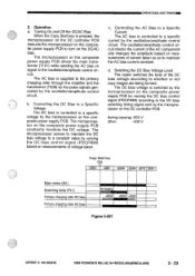
... composite power supply PCB drives the main transformer (T101) while sending the AC bias on the composite power supply PCB constantly monitors the DC voltage. c. d. CANON PC720/740/750/770 REV.O AUG.1994 PRINTED IN JAPAN omput AU JAPON) 3 - 23 The AC bias is supplied to the primary charging roller through the... STBY Main motor (M1) Scanning lamp (FL1) Primary charging roller DC bias Primary charging roller AC bias P e-heatn -400V -625V -400V Figure 3-307 COPYRIGHT O 1994 CANON INC.
... composite power supply PCB drives the main transformer (T101) while sending the AC bias on the composite power supply PCB constantly monitors the DC voltage. c. d. CANON PC720/740/750/770 REV.O AUG.1994 PRINTED IN JAPAN omput AU JAPON) 3 - 23 The AC bias is supplied to the primary charging roller through the... STBY Main motor (M1) Scanning lamp (FL1) Primary charging roller DC bias Primary charging roller AC bias P e-heatn -400V -625V -400V Figure 3-307 COPYRIGHT O 1994 CANON INC.
Service Manual
Page 68
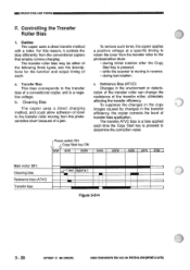
...allow adhesion of a conventional copier, and is a negative voltage. The transfer ATVC bias is moving from the conventional copiers that employ corona charging. CANON PC720/74000770 REV.O AUG.1994 PRINTED IN JAPAN pmpFeat AU JAPAN) c. Reference Bias (ATVC) Changes in the transfer efficiency, the copier corrects the level...STBY Main motor (M1) Cleaning bias Reference bias (ATVC) Transfer bias sec (approx.) U Figure 3-314 3 - 28 COPYRIGHT © 1994 CANON INC. To suppress the changes in the copy images caused by changes in the environment or deterio- b. OPERATIONS AND TIMING F.
...allow adhesion of a conventional copier, and is a negative voltage. The transfer ATVC bias is moving from the conventional copiers that employ corona charging. CANON PC720/74000770 REV.O AUG.1994 PRINTED IN JAPAN pmpFeat AU JAPAN) c. Reference Bias (ATVC) Changes in the transfer efficiency, the copier corrects the level...STBY Main motor (M1) Cleaning bias Reference bias (ATVC) Transfer bias sec (approx.) U Figure 3-314 3 - 28 COPYRIGHT © 1994 CANON INC. To suppress the changes in the copy images caused by changes in the environment or deterio- b. OPERATIONS AND TIMING F.

Service Manual
Page 74
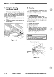
If fogging is dark enough. . CANON PC720/74750/770 REY.0 AUG.1994 PRINTEDINJAPANpMPRIMEAU JAPON) =OPERATIONS AND TIMING 9) Make one copy, and check if it is free of fogging but the print is noted or the characters are too light, repeat the steps starting with step 1) once again. • If the problem cannot be corrected after going through the steps once again, use the density correction switch (SW101). 0 D SW101 Figure 3-323 3 - 34 COPYRIGHT © 1994 CANON INC.
If fogging is dark enough. . CANON PC720/74750/770 REY.0 AUG.1994 PRINTEDINJAPANpMPRIMEAU JAPON) =OPERATIONS AND TIMING 9) Make one copy, and check if it is free of fogging but the print is noted or the characters are too light, repeat the steps starting with step 1) once again. • If the problem cannot be corrected after going through the steps once again, use the density correction switch (SW101). 0 D SW101 Figure 3-323 3 - 34 COPYRIGHT © 1994 CANON INC.
Service Manual
Page 91
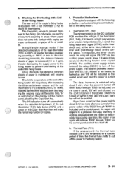
...a. Protection Mechanisms The copier is equipped with `E0', i.e., related to a press on paper of A4 or small- If you turned off . COPYRIGHT 0 1994 CANON INC. at the same time, 'H' is indicated in turn turns off the relay (RL601) to turn itself off the power switch while 'E000' through E003... Heater The rear end of the copier's fixing heater is retained only about 5 min or more , copying operation is turned on the control panel. CANON PC720/740/7501770 REV.() AUG. 1994 PRINTED IN JAPAN piPoit AU JAPAN) 3 - 51 Thermal Fuse (FU1) If the area around the thermal fuse exceeds...
...a. Protection Mechanisms The copier is equipped with `E0', i.e., related to a press on paper of A4 or small- If you turned off . COPYRIGHT 0 1994 CANON INC. at the same time, 'H' is indicated in turn turns off the relay (RL601) to turn itself off the power switch while 'E000' through E003... Heater The rear end of the copier's fixing heater is retained only about 5 min or more , copying operation is turned on the control panel. CANON PC720/740/7501770 REV.() AUG. 1994 PRINTED IN JAPAN piPoit AU JAPAN) 3 - 51 Thermal Fuse (FU1) If the area around the thermal fuse exceeds...

Service Manual
Page 96
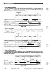
CANON PC720/74017501/70 REV.O AUG.1994 PRINTEDIN JAPAN (MPRIME AU JAPON) IMMA OPERATIONS AND TIMING Copy Start key ON STBY INTR SCFW Pick-up clutch solenoid (SL1) Jam check Registration sensor (Q751) Main motor (M1) 2.1 sec No paper 1.5 sec Figure 3-422 (no paper) Copy Start key ON STBY INTR SCFW Pick-up clutch solenoid (SL1) Jam check Registration sensor (Q751) Main motor (M1) 2.1 sec No paper Jam 1.5 sec Figure 3-423 (jam) 3 - 56 COPYRIGHT © 1994 CANON INC.
CANON PC720/74017501/70 REV.O AUG.1994 PRINTEDIN JAPAN (MPRIME AU JAPON) IMMA OPERATIONS AND TIMING Copy Start key ON STBY INTR SCFW Pick-up clutch solenoid (SL1) Jam check Registration sensor (Q751) Main motor (M1) 2.1 sec No paper 1.5 sec Figure 3-422 (no paper) Copy Start key ON STBY INTR SCFW Pick-up clutch solenoid (SL1) Jam check Registration sensor (Q751) Main motor (M1) 2.1 sec No paper Jam 1.5 sec Figure 3-423 (jam) 3 - 56 COPYRIGHT © 1994 CANON INC.
Service Manual
Page 98
.... SCFW SCRV SCFW SCRV SCFW Jam check Delivery sensor (PS4) Main motor (WI) 4.3 sec I. 4.3 sec II 4 Normal I Figure 3-428 Jam sec 3 - 58 COPYRIGHT 1994 CANONINC. CANON PC720/740R501770REV.OAUG.1994 PRINTEDIN JAPANDMPRIMEAUJAPON) Copy Start key ON 81, V STBY INTR SCFW SCRV SCFW Registration clutch solenoid (SL2) Jam check Delivery sensor (PS4) Main...
.... SCFW SCRV SCFW SCRV SCFW Jam check Delivery sensor (PS4) Main motor (WI) 4.3 sec I. 4.3 sec II 4 Normal I Figure 3-428 Jam sec 3 - 58 COPYRIGHT 1994 CANONINC. CANON PC720/740R501770REV.OAUG.1994 PRINTEDIN JAPANDMPRIMEAUJAPON) Copy Start key ON 81, V STBY INTR SCFW SCRV SCFW Registration clutch solenoid (SL2) Jam check Delivery sensor (PS4) Main...
Service Manual
Page 100
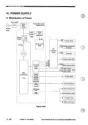
.../ +24V►U main motor driver PCB O Fixing heater Scanning lamp Primary charging roller Developing roller Transfer roller Static eliminator 3 - 60 COPYRIGHT © 1994 CANON INC. POWER SUPPLY A. CANON PC720/7401750(170 REY.O AUG.1994 PRINTED IN JAPAN pmPRimt AU JAPON) Distribution of Power Door switch DS1 Power plug Noise filter circuit Relay RL601...
.../ +24V►U main motor driver PCB O Fixing heater Scanning lamp Primary charging roller Developing roller Transfer roller Static eliminator 3 - 60 COPYRIGHT © 1994 CANON INC. POWER SUPPLY A. CANON PC720/7401750(170 REY.O AUG.1994 PRINTED IN JAPAN pmPRimt AU JAPON) Distribution of Power Door switch DS1 Power plug Noise filter circuit Relay RL601...
Service Manual
Page 101
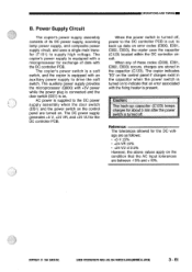
...drive the soft switch. Caution: The back-up data on the control panel if charges exist in the capacitor (C123). COPYRIGHT © 1994 CANON INC. The copier indicates `E0' on error codes (E000, E001, E002, E003), the copier uses the capacitor (C123) located within the... composite power supply circuit, and uses a single main transfer (T101) to the DC controller PCB is turned off , power to supply high voltage. CANON PC720/14017501770 REVD AUG. 1994 PRINTED IN JAPAN ompRat AU JAPON) 3 - 61 OPERATIONS AND TIMINGIIIIIIII B. The copier's power supply is equipped with a microprocessor...
...drive the soft switch. Caution: The back-up data on the control panel if charges exist in the capacitor (C123). COPYRIGHT © 1994 CANON INC. The copier indicates `E0' on error codes (E000, E001, E002, E003), the copier uses the capacitor (C123) located within the... composite power supply circuit, and uses a single main transfer (T101) to the DC controller PCB is turned off , power to supply high voltage. CANON PC720/14017501770 REVD AUG. 1994 PRINTED IN JAPAN ompRat AU JAPON) 3 - 61 OPERATIONS AND TIMINGIIIIIIII B. The copier's power supply is equipped with a microprocessor...

Service Manual
Page 104
adjust the intensity of the scanning lamp 2. Actions to Take After Replacement Part Work Scanning lamp 1. adjust the intensity of the scanning lamp 2. CANON PC720/740850/770 REV.O AUG. 1994 PRINTED IN JAPAN (IMPRIME AU JAPAN) INNOPERATIONS AND TIMING VII. adjust the intensity of the scanning lamp 2. adjust the intensity ... edge non-image width 4. image leading edge margin 5. execute AE adjustment Composite power supply PCB 1. fine-adjust reproduction ratio Table 3-701 3 - 64 COPYRIGHT © 1994 CANON INC.
adjust the intensity of the scanning lamp 2. Actions to Take After Replacement Part Work Scanning lamp 1. adjust the intensity of the scanning lamp 2. CANON PC720/740850/770 REV.O AUG. 1994 PRINTED IN JAPAN (IMPRIME AU JAPAN) INNOPERATIONS AND TIMING VII. adjust the intensity of the scanning lamp 2. adjust the intensity ... edge non-image width 4. image leading edge margin 5. execute AE adjustment Composite power supply PCB 1. fine-adjust reproduction ratio Table 3-701 3 - 64 COPYRIGHT © 1994 CANON INC.
Service Manual
Page 107
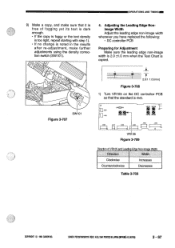
... 0 SW101 Figure 3-707 2.0± 1.0 [aim] Figure 3-708 1) Turn VR105 on the DC controller PCB so that it is met. CANON PC720/7401750M0 RED AUG.1994 PRINTED IN JAPAN (IMPRIME AU JAPON) 3 - 67 Direction Width Clockwise Increases Counterclockwise Decreases Table 3-703 COPYRIGHT © 1994... CANON INC. O Jpal]Ova V2104 V2205 E 221101 22002 18 V0102 V0103 J105 I 12 VR105 Figure 3-709 .009 O " Direction of fogging yet...
... 0 SW101 Figure 3-707 2.0± 1.0 [aim] Figure 3-708 1) Turn VR105 on the DC controller PCB so that it is met. CANON PC720/7401750M0 RED AUG.1994 PRINTED IN JAPAN (IMPRIME AU JAPON) 3 - 67 Direction Width Clockwise Increases Counterclockwise Decreases Table 3-703 COPYRIGHT © 1994... CANON INC. O Jpal]Ova V2104 V2205 E 221101 22002 18 V0102 V0103 J105 I 12 VR105 Figure 3-709 .009 O " Direction of fogging yet...
Service Manual
Page 109
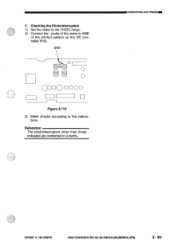
Checking the Photointerrupters 1) Set the meter to the instructions. J rc c), O00O 0000 I 1 Figure 3-713 3) Make checks according to the 12VDC range. 2) Connect the - probe of the meter to GND of the printed pattern on the DC controller PCB. OPERATIONS AND TIMING= COPYRIGHT © 1994 CANON INC. GND ce \-(7-,). CANON PC720/7401150770 REVD AUG.1994 PRINTED IN JAPAN RAPPoit AU JAPON) 3 - 69 7. Reference: The photointerrupters other than those indicated are connected in a matrix.
Checking the Photointerrupters 1) Set the meter to the instructions. J rc c), O00O 0000 I 1 Figure 3-713 3) Make checks according to the 12VDC range. 2) Connect the - probe of the meter to GND of the printed pattern on the DC controller PCB. OPERATIONS AND TIMING= COPYRIGHT © 1994 CANON INC. GND ce \-(7-,). CANON PC720/7401150770 REVD AUG.1994 PRINTED IN JAPAN RAPPoit AU JAPON) 3 - 69 7. Reference: The photointerrupters other than those indicated are connected in a matrix.


