Scanner Driver Guide MF4600 Series
Page 14
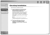
Open the [Scanners and Cameras] folder (Windows 98/2000: the [Scanners and Cameras Properties] dialog box). If the [Canon MF Toolbox 4.9] icon is displayed on the Windows desktop, installation of Contents Index Back Previous Next TOP 1-4 Windows 98/Me/2000: [Start]... driver icon is installed successfully. 1. NOTE If the driver has not been installed on the Windows task bar → select [Control Panel] → [Printers and other Hardware] → [Scanners and Cameras]. (Windows Vista: [start ] on your computer, see "Installing/Uninstalling Software" in the Starter Guide and...
Open the [Scanners and Cameras] folder (Windows 98/2000: the [Scanners and Cameras Properties] dialog box). If the [Canon MF Toolbox 4.9] icon is displayed on the Windows desktop, installation of Contents Index Back Previous Next TOP 1-4 Windows 98/Me/2000: [Start]... driver icon is installed successfully. 1. NOTE If the driver has not been installed on the Windows task bar → select [Control Panel] → [Printers and other Hardware] → [Scanners and Cameras]. (Windows Vista: [start ] on your computer, see "Installing/Uninstalling Software" in the Starter Guide and...

Scanner Driver Guide MF4600 Series
Page 19
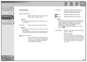
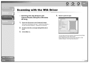
... function you can set it up other Hardware] → [Scanners and Cameras]. (Windows Vista: [start ] on the Windows task bar → select [Control Panel] → [Printers and other applications which have not been registered to MF Toolbox 1. Windows 98/Me/2000: [Start] → [Settings] → [Control Panel] → double-click [Scanners...
... function you can set it up other Hardware] → [Scanners and Cameras]. (Windows Vista: [start ] on the Windows task bar → select [Control Panel] → [Printers and other applications which have not been registered to MF Toolbox 1. Windows 98/Me/2000: [Start] → [Settings] → [Control Panel] → double-click [Scanners...
Scanner Driver Guide MF4600 Series
Page 39
NOTE - Some applications have a limit to a monochrome printer. The contrast in the image is divided at certain levels (threshold values) into black and white and is displayed in which it is scanned. [Black ...
NOTE - Some applications have a limit to a monochrome printer. The contrast in the image is divided at certain levels (threshold values) into black and white and is displayed in which it is scanned. [Black ...
Scanner Driver Guide MF4600 Series
Page 51
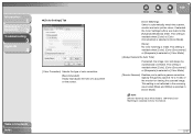
...], [Color (Documents)] or [Grayscale] is selected in the [Advanced Mode] tab sheet. Specify the gamma value (0.10 to automatically match the scanner, monitor and color printer colors. Table of Contents Index 2-37 NOTE [Monitor Gamma] value will always be fixed to perform gamma correction. Back Previous Next TOP [Color Matching]: Select...
...], [Color (Documents)] or [Grayscale] is selected in the [Advanced Mode] tab sheet. Specify the gamma value (0.10 to automatically match the scanner, monitor and color printer colors. Table of Contents Index 2-37 NOTE [Monitor Gamma] value will always be fixed to perform gamma correction. Back Previous Next TOP [Color Matching]: Select...
Scanner Driver Guide MF4600 Series
Page 53
... resolution, the image data will be reduced by half. You can print the document with sufficient quality, even if you double the size of the printer. Make sure the resolution corresponds to scan at double the resolution so that you can specify a resolution in [Image Quality] in the MF Toolbox settings... dialog box, or in [Output Resolution] in the ScanGear MF. ● Images for Display on a monitor in one inch. NOTE With a color printer, the colors are expressed as lack of your document at half the resolution of the...
... resolution, the image data will be reduced by half. You can print the document with sufficient quality, even if you double the size of the printer. Make sure the resolution corresponds to scan at double the resolution so that you can specify a resolution in [Image Quality] in the MF Toolbox settings... dialog box, or in [Output Resolution] in the ScanGear MF. ● Images for Display on a monitor in one inch. NOTE With a color printer, the colors are expressed as lack of your document at half the resolution of the...
Scanner Driver Guide MF4600 Series
Page 54
... from [Color picture], [Grayscale picture], [Black and white picture or text], and [Custom]. Click [start] on the Windows task bar → select [Control Panel] → [Printers and Other Hardware] → [Scanners and Cameras]. 2. Select a picture type. Open the [Scanners and Cameras] folder.
... from [Color picture], [Grayscale picture], [Black and white picture or text], and [Custom]. Click [start] on the Windows task bar → select [Control Panel] → [Printers and Other Hardware] → [Scanners and Cameras]. 2. Select a picture type. Open the [Scanners and Cameras] folder.
Scanner Driver Guide MF4600 Series
Page 65
... reinstall it . (See "Installing/Uninstalling Software," in particular when scanning large documents at one time on the Windows task bar → select [Control Panel] → [Printers and other opened applications and try again. Click a button on the MF Toolbox and, in [Preferences] selected? A Change the allocated memory in your computer? Change...
... reinstall it . (See "Installing/Uninstalling Software," in particular when scanning large documents at one time on the Windows task bar → select [Control Panel] → [Printers and other opened applications and try again. Click a button on the MF Toolbox and, in [Preferences] selected? A Change the allocated memory in your computer? Change...

Scanner Driver Guide MF4600 Series
Page 72
... captured by a scanner consistent with those output by a particular monitor. Control Panel The set of an image for an image on a printer. Using the Crop button on whether the brightness value is a two-color image. An 8-bit grayscale image expresses an image in the final... part of Windows programs you can be slightly different than those shown on a display or printed on the monitor may be displayed by a printer. Brightness The relative proportion of an image. The result is above or below a particular threshold value. Decreasing brightness darkens the overall image; ...
... captured by a scanner consistent with those output by a particular monitor. Control Panel The set of an image for an image on a printer. Using the Crop button on whether the brightness value is a two-color image. An 8-bit grayscale image expresses an image in the final... part of Windows programs you can be slightly different than those shown on a display or printed on the monitor may be displayed by a printer. Brightness The relative proportion of an image. The result is above or below a particular threshold value. Decreasing brightness darkens the overall image; ...
Scanner Driver Guide MF4600 Series
Page 74
... of the image, which means you can be used to a designated location on a computer's hard disk so that enables them to share equipment (such as printers) and exchange information. K Kilobyte (KB) A unit of measurement, representing the binary number 1024, used at any time. Introduction 1 Scanning a Document 2 Troubleshooting 3 Appendix 4 G Gamma Correction Method...
... of the image, which means you can be used to a designated location on a computer's hard disk so that enables them to share equipment (such as printers) and exchange information. K Kilobyte (KB) A unit of measurement, representing the binary number 1024, used at any time. Introduction 1 Scanning a Document 2 Troubleshooting 3 Appendix 4 G Gamma Correction Method...

imageCLASS MF4690 Starter Guide
Page 12
... Functions]. 2 Press [ ] or [ ] to select , then press [OK]. 3 Press [ ] or [ ] to do is configured to provide a DHCP address, all you use the machine as a local printer, connect the machine directly to a network router or a hub. Set the Machine for Network Usage Connect the Machine to enable communication between the machine and...
... Functions]. 2 Press [ ] or [ ] to select , then press [OK]. 3 Press [ ] or [ ] to do is configured to provide a DHCP address, all you use the machine as a local printer, connect the machine directly to a network router or a hub. Set the Machine for Network Usage Connect the Machine to enable communication between the machine and...
imageCLASS MF4690 Starter Guide
Page 14
... is available only through optimization. If you can be delegated to install the software. • Make sure the machine is the Canon UFRII LT printer driver. Microsoft Windows XP (32-bit version) CPU: Intel Pentium/Celeron series 300 MHz or faster Memory: 128 MB or more ... as Administrator to match the output data, thus realizing a significant increase in speed through a USB connection. This machine supports the PCL5e and PCL6 printer drivers. ● UFRII LT: This is turned on before installing the software. Windows 98/Me/2000: doubleclick [My Computer] on the circled button...
... is available only through optimization. If you can be delegated to install the software. • Make sure the machine is the Canon UFRII LT printer driver. Microsoft Windows XP (32-bit version) CPU: Intel Pentium/Celeron series 300 MHz or faster Memory: 128 MB or more ... as Administrator to match the output data, thus realizing a significant increase in speed through a USB connection. This machine supports the PCL5e and PCL6 printer drivers. ● UFRII LT: This is turned on before installing the software. Windows 98/Me/2000: doubleclick [My Computer] on the circled button...
imageCLASS MF4690 Starter Guide
Page 17
...the Windows task bar → [(All) Programs] → [Canon] → [MF4600 Series] → [Uninstall Drivers]. The [MF Drivers Uninstaller] dialog box appears. 2 Click [Delete]. 31 1 Open the [Printers and Faxes] folder (Windows 98/2000: the [Printers] dialog box). Windows Vista: Click [start ] on the Windows ..., check [Remove], then click [Next >]. NOTE When you opened the [printer] screen from [File] menu. Make sure the corresponding scanner driver icon is displayed. 4 Check if there is the [Canon MF Toolbox 4.9] icon on -screen instructions. 3 Click [Yes]. Uninstallation Procedure...
...the Windows task bar → [(All) Programs] → [Canon] → [MF4600 Series] → [Uninstall Drivers]. The [MF Drivers Uninstaller] dialog box appears. 2 Click [Delete]. 31 1 Open the [Printers and Faxes] folder (Windows 98/2000: the [Printers] dialog box). Windows Vista: Click [start ] on the Windows ..., check [Remove], then click [Next >]. NOTE When you opened the [printer] screen from [File] menu. Make sure the corresponding scanner driver icon is displayed. 4 Check if there is the [Canon MF Toolbox 4.9] icon on -screen instructions. 3 Click [Yes]. Uninstallation Procedure...
Service Manual
Page 7
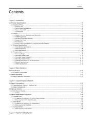
... 1.1.2.3 Handling of the Laser Assembly ...1- 6 1.1.2.4 Safety of the Toner ...1- 6 1.1.2.5 Fire Attention...1- 6 1.1.2.6 Points no Note when Replacing / Disposing the Lithium Battery 1- 7 1.1.3 Product Specifications ...1- 7 1.1.3.1 Host Machine Specifications...1- 7 1.1.3.2 ADF Specifications...1- 8 1.1.3.3 FAX Specifications...1- 8 1.1.4 Function List ...1- 9 1.1.4.1 Scanning Range ...1- 9 1.1.4.2 Recording Range (Copy) ...1- 10 1.1.4.3 Recording Range (Reception) ...1- 10 1.1.4.4 Recording Range (Printer) ...1- 11 1.1.4.5 Operation Environment of the Printer Driver...1- 11 1.1.4.6 Network...
... 1.1.2.3 Handling of the Laser Assembly ...1- 6 1.1.2.4 Safety of the Toner ...1- 6 1.1.2.5 Fire Attention...1- 6 1.1.2.6 Points no Note when Replacing / Disposing the Lithium Battery 1- 7 1.1.3 Product Specifications ...1- 7 1.1.3.1 Host Machine Specifications...1- 7 1.1.3.2 ADF Specifications...1- 8 1.1.3.3 FAX Specifications...1- 8 1.1.4 Function List ...1- 9 1.1.4.1 Scanning Range ...1- 9 1.1.4.2 Recording Range (Copy) ...1- 10 1.1.4.3 Recording Range (Reception) ...1- 10 1.1.4.4 Recording Range (Printer) ...1- 11 1.1.4.5 Operation Environment of the Printer Driver...1- 11 1.1.4.6 Network...
Service Manual
Page 10
Contents 9.3.6.1 Preparation for Removing the Printer Cover...9- 3 9.3.6.2 Removing the Printer Cover...9- 3 9.3.7 Operation Panel Unit...9- 4 9.3.7.1 Removing the Control Panel Unit...9- 4 9.3.8 SCNT Board...9- 4 9.3.8.1 Preparation for Removing the SCNT Board...9- 4 9.3.8.2 Removing the SCNT Board ...9- 4 9.3.8.3 Actions At Replacing the ...
Contents 9.3.6.1 Preparation for Removing the Printer Cover...9- 3 9.3.6.2 Removing the Printer Cover...9- 3 9.3.7 Operation Panel Unit...9- 4 9.3.7.1 Removing the Control Panel Unit...9- 4 9.3.8 SCNT Board...9- 4 9.3.8.1 Preparation for Removing the SCNT Board...9- 4 9.3.8.2 Removing the SCNT Board ...9- 4 9.3.8.3 Actions At Replacing the ...
Service Manual
Page 12
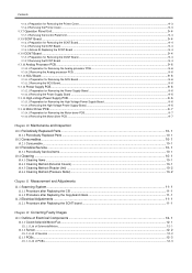
Contents 14.3.11.3 Detailed Discussions of Bit 1...14- 12 14.3.11.4 Detailed Discussions of Bit 2...14- 12 14.3.11.5 Detailed Discussions of Bit 3...14- 12 14.3.11.6 Detailed Discussions of Bit 4...14- 12 14.3.11.7 Detailed Discussions of Bit 5...14- 12 14.3.12 SSSW-SW30...14- 12 14.3.12.1 List of Functions ...14- 12 14.3.12.2 Detailed Discussions of Bit 5...14- 12 14.4 Menu Switch Settings (MENU) ...14- 12 14.4.1 Menu Switch Composition...14- 12 14.4.2 ...14- 13 14.4.3 ...14- 13 14.4.4 ...14- 13 14.4.5 ...14- 13 14.4.6 ...14- 13 14.4.7 ...14- 13 14.5 Numeric Parameter Settings (NUMERIC ...
Contents 14.3.11.3 Detailed Discussions of Bit 1...14- 12 14.3.11.4 Detailed Discussions of Bit 2...14- 12 14.3.11.5 Detailed Discussions of Bit 3...14- 12 14.3.11.6 Detailed Discussions of Bit 4...14- 12 14.3.11.7 Detailed Discussions of Bit 5...14- 12 14.3.12 SSSW-SW30...14- 12 14.3.12.1 List of Functions ...14- 12 14.3.12.2 Detailed Discussions of Bit 5...14- 12 14.4 Menu Switch Settings (MENU) ...14- 12 14.4.1 Menu Switch Composition...14- 12 14.4.2 ...14- 13 14.4.3 ...14- 13 14.4.4 ...14- 13 14.4.5 ...14- 13 14.4.6 ...14- 13 14.4.7 ...14- 13 14.5 Numeric Parameter Settings (NUMERIC ...
Service Manual
Page 17
......1-6 1.1.2.3 Handling of the Laser Assembly...1-6 1.1.2.4 Safety of the Toner...1-6 1.1.2.5 Fire Attention ...1-6 1.1.2.6 Points no Note when Replacing / Disposing the Lithium Battery ...1-7 1.1.3 Product Specifications ...1-7 1.1.3.1 Host Machine Specifications...1-7 1.1.3.2 ADF Specifications ...1-8 1.1.3.3 FAX Specifications ...1-8 1.1.4 Function List ...1-9 1.1.4.1 Scanning Range...1-9 1.1.4.2 Recording Range (Copy)...1-10 1.1.4.3 Recording Range (Reception) ...1-10 1.1.4.4 Recording Range (Printer) ...1-11 1.1.4.5 Operation Environment of the Printer Driver ...1-11 1.1.4.6 Network...
......1-6 1.1.2.3 Handling of the Laser Assembly...1-6 1.1.2.4 Safety of the Toner...1-6 1.1.2.5 Fire Attention ...1-6 1.1.2.6 Points no Note when Replacing / Disposing the Lithium Battery ...1-7 1.1.3 Product Specifications ...1-7 1.1.3.1 Host Machine Specifications...1-7 1.1.3.2 ADF Specifications ...1-8 1.1.3.3 FAX Specifications ...1-8 1.1.4 Function List ...1-9 1.1.4.1 Scanning Range...1-9 1.1.4.2 Recording Range (Copy)...1-10 1.1.4.3 Recording Range (Reception) ...1-10 1.1.4.4 Recording Range (Printer) ...1-11 1.1.4.5 Operation Environment of the Printer Driver ...1-11 1.1.4.6 Network...
Service Manual
Page 29
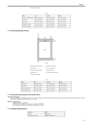
... mm 2.0 +2.0/-2.0 mm 2.0 +2.0/-2.0 mm 6.0 +2.0/-2.0 mm Legal 212 +2.0/-2.0 mm 2.0 +2.0/-2.0 mm 2.0 +2.0/-2.0 mm 2.0 +2.0/-2.0 mm 6.0 +2.0/-2.0 mm 1.1.4.4 Recording Range (Printer) [1] [2] [4] [3] [7] [5] Chapter 1 0016-1786 [8] [9] [1] leading edge of document [2] left margin [3] effective scanning width [4] right margin [5] leading ... mm Legal 5.0 +2.0/-2.0 mm 5.0 +2.0/-2.0 mm 6.0 +2.0/-2.0 mm 6.0 +2.0/-2.0 mm 1.1.4.5 Operation Environment of the Printer Driver 0016-1788 Operation environment Microsoft Windows 98/98SE/Me, Windows 2000 Server, Windows 2000 Professional, Windows XP ...
... mm 2.0 +2.0/-2.0 mm 2.0 +2.0/-2.0 mm 6.0 +2.0/-2.0 mm Legal 212 +2.0/-2.0 mm 2.0 +2.0/-2.0 mm 2.0 +2.0/-2.0 mm 2.0 +2.0/-2.0 mm 6.0 +2.0/-2.0 mm 1.1.4.4 Recording Range (Printer) [1] [2] [4] [3] [7] [5] Chapter 1 0016-1786 [8] [9] [1] leading edge of document [2] left margin [3] effective scanning width [4] right margin [5] leading ... mm Legal 5.0 +2.0/-2.0 mm 5.0 +2.0/-2.0 mm 6.0 +2.0/-2.0 mm 6.0 +2.0/-2.0 mm 1.1.4.5 Operation Environment of the Printer Driver 0016-1788 Operation environment Microsoft Windows 98/98SE/Me, Windows 2000 Server, Windows 2000 Professional, Windows XP ...

Service Manual
Page 35
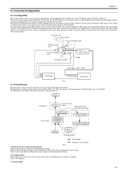
System Control System Scanning Control System Laser / Scanner System Printer Control System Image Formation System Fixing System Pickup / Feeding System F-2-1 2.2 Basic Sequence 2.2.1 Basic Operation Sequence 0016-1810 The ...2 2.1.1 Function Configuration 0016-1809 The functions of this host machine are mainly composed of the 7 blocks: System Control System, Scanning Control System, Printer Control System, Laser Scanner System, Image Formation System, Fixing System, Pickup/Feeding System. interval name WAIT (wait) STBY (standby) definition of interval purpose T-2-1 remarks ...
System Control System Scanning Control System Laser / Scanner System Printer Control System Image Formation System Fixing System Pickup / Feeding System F-2-1 2.2 Basic Sequence 2.2.1 Basic Operation Sequence 0016-1810 The ...2 2.1.1 Function Configuration 0016-1809 The functions of this host machine are mainly composed of the 7 blocks: System Control System, Scanning Control System, Printer Control System, Laser Scanner System, Image Formation System, Fixing System, Pickup/Feeding System. interval name WAIT (wait) STBY (standby) definition of interval purpose T-2-1 remarks ...
Service Manual
Page 69
...this machine has the main 5 blocks and 7 steps. Fixing film area Cleaner blade Primary charging roller Photosensitive drum Transfer charging roller Laser beam Blade Laser / scanner block Developing cylinder Cartridge Video signal VDO /VDO PR1 TRS DEV DCNT board Print command SCNT board F-6-1 6.1.2 Print ..., /VDO) is transferred on papers by following is made even by the printer. The surface of the photosensitive drum is evenly charged negative by the primary charging roller, and the laser beam converted with the toner on the surface of the photosensitive drum, whose ...
...this machine has the main 5 blocks and 7 steps. Fixing film area Cleaner blade Primary charging roller Photosensitive drum Transfer charging roller Laser beam Blade Laser / scanner block Developing cylinder Cartridge Video signal VDO /VDO PR1 TRS DEV DCNT board Print command SCNT board F-6-1 6.1.2 Print ..., /VDO) is transferred on papers by following is made even by the printer. The surface of the photosensitive drum is evenly charged negative by the primary charging roller, and the laser beam converted with the toner on the surface of the photosensitive drum, whose ...
Service Manual
Page 72
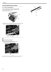
... direction of the bushing. - Chapter 6 6.4 Parts Replacement Procedure 6.4.1 Transfer Charging Roller 6.4.1.1 Removing the Transfer Charging Roller 0016-5039 1) Open the control panel assembly [1]. 2) Open the printer cover [2]. Insert the spring [1] into the boss [2] of the arrow. Points to remove the transfer charging roller [3] with bare hands. F-6-3 3) Unhook the 2 claws [1] and the...
... direction of the bushing. - Chapter 6 6.4 Parts Replacement Procedure 6.4.1 Transfer Charging Roller 6.4.1.1 Removing the Transfer Charging Roller 0016-5039 1) Open the control panel assembly [1]. 2) Open the printer cover [2]. Insert the spring [1] into the boss [2] of the arrow. Points to remove the transfer charging roller [3] with bare hands. F-6-3 3) Unhook the 2 claws [1] and the...


