imageCLASS MF4690 Starter Guide
Page 3
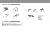
... lists ● Scanner Driver Guide (located on the User Software CD): Scanner settings from a computer 3 ●Power Cord ●Telephone Cable ●Destination Labels ●Toner Cartridge ●Starter Guide (This Document) ●Basic Operation Guide ●User Software CD ●Reference Guide (located on User Software CD) ●Scanner Driver...
... lists ● Scanner Driver Guide (located on the User Software CD): Scanner settings from a computer 3 ●Power Cord ●Telephone Cable ●Destination Labels ●Toner Cartridge ●Starter Guide (This Document) ●Basic Operation Guide ●User Software CD ●Reference Guide (located on User Software CD) ●Scanner Driver...
imageCLASS MF4690 Starter Guide
Page 4
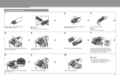
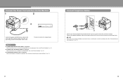
... using the tab (A) which covers over on the right side of the machine and slide it to the guide. If you cannot close the toner cover, do not force it down parallel to close. Keep the bag for future use. 4 A A CAUTION Do not open the drum protective shutter (A). 5 A ...Lift the scanning platform (A) until it is properly set in the machine. 6 Install Toner Cartridge 1 Remove the toner cartridge from the bag. Open the cover and make sure it is locked. (You will hear an audible "click.") B Open the...
... using the tab (A) which covers over on the right side of the machine and slide it to the guide. If you cannot close the toner cover, do not force it down parallel to close. Keep the bag for future use. 4 A A CAUTION Do not open the drum protective shutter (A). 5 A ...Lift the scanning platform (A) until it is properly set in the machine. 6 Install Toner Cartridge 1 Remove the toner cartridge from the bag. Open the cover and make sure it is locked. (You will hear an audible "click.") B Open the...
imageCLASS MF4690 Starter Guide
Page 7
What if... ● is displayed: Make sure that the toner cover and scanning platform are closed properly. (See "Install Toner Cartridge," on p. 5.) ● is displayed: Make sure that the toner cartridge is installed properly. (See "Install Toner Cartridge," on p. 5.) ● is displayed: Make sure that paper is loaded in the machine. (See "Set Up the...
What if... ● is displayed: Make sure that the toner cover and scanning platform are closed properly. (See "Install Toner Cartridge," on p. 5.) ● is displayed: Make sure that the toner cartridge is installed properly. (See "Install Toner Cartridge," on p. 5.) ● is displayed: Make sure that paper is loaded in the machine. (See "Set Up the...
Service Manual
Page 7
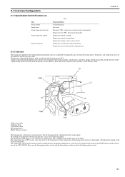
... of Parts...1- 1 1.1.1.1 External View ...1- 1 1.1.1.2 Section View (Host Machine)...1- 3 1.1.1.3 Section View (ADF)...1- 3 1.1.1.4 Control panel...1- 4 1.1.2 Safety ...1- 6 1.1.2.1 Safety of the Host Machine's Laser Mechanism ...1- 6 1.1.2.2 CDRH Regulations...1- 6 1.1.2.3 Handling of the Laser Assembly ...1- 6 1.1.2.4 Safety of the Toner ...1- 6 1.1.2.5 Fire Attention...1- 6 1.1.2.6 Points no Note when Replacing / Disposing the Lithium Battery 1- 7 1.1.3 Product Specifications ...1- 7 1.1.3.1 Host Machine Specifications...1- 7 1.1.3.2 ADF Specifications...1- 8 1.1.3.3 FAX Specifications...
... of Parts...1- 1 1.1.1.1 External View ...1- 1 1.1.1.2 Section View (Host Machine)...1- 3 1.1.1.3 Section View (ADF)...1- 3 1.1.1.4 Control panel...1- 4 1.1.2 Safety ...1- 6 1.1.2.1 Safety of the Host Machine's Laser Mechanism ...1- 6 1.1.2.2 CDRH Regulations...1- 6 1.1.2.3 Handling of the Laser Assembly ...1- 6 1.1.2.4 Safety of the Toner ...1- 6 1.1.2.5 Fire Attention...1- 6 1.1.2.6 Points no Note when Replacing / Disposing the Lithium Battery 1- 7 1.1.3 Product Specifications ...1- 7 1.1.3.1 Host Machine Specifications...1- 7 1.1.3.2 ADF Specifications...1- 8 1.1.3.3 FAX Specifications...
Service Manual
Page 8
... of Fault of the Scanner Motor ...5- 3 5.5 Parts Replacement Procedure ...5- 4 5.5.1 Laser/Scanner Unit ...5- 4 5.5.1.1 Preparation for Removing the Laser Scanner Unit ...5- 4 5.5.1.2 Removing the Laser Scanner Unit ...5- 4 Chapter 6 Image Formation 6.1 Overview/Configuration ...6- 1 6.1.1 Configuration...6- 1 6.1.2 Print Process...6- 1 6.2 Driving and Controlling the High-Voltage System 6- 3 6.2.1 Generation of Transfer Charging Bias ...6- 3 6.3 Toner Cartridge ...6- 3 6.3.1 Toner Level Detection...6- 3 6.4 Parts Replacement Procedure ...6- 4 6.4.1 Transfer Charging Roller...
... of Fault of the Scanner Motor ...5- 3 5.5 Parts Replacement Procedure ...5- 4 5.5.1 Laser/Scanner Unit ...5- 4 5.5.1.1 Preparation for Removing the Laser Scanner Unit ...5- 4 5.5.1.2 Removing the Laser Scanner Unit ...5- 4 Chapter 6 Image Formation 6.1 Overview/Configuration ...6- 1 6.1.1 Configuration...6- 1 6.1.2 Print Process...6- 1 6.2 Driving and Controlling the High-Voltage System 6- 3 6.2.1 Generation of Transfer Charging Bias ...6- 3 6.3 Toner Cartridge ...6- 3 6.3.1 Toner Level Detection...6- 3 6.4 Parts Replacement Procedure ...6- 4 6.4.1 Transfer Charging Roller...
Service Manual
Page 17
... 1.1.1 Names of Parts ...1-1 1.1.1.1 External View...1-1 1.1.1.2 Section View (Host Machine) ...1-3 1.1.1.3 Section View (ADF) ...1-3 1.1.1.4 Control panel...1-4 1.1.2 Safety ...1-6 1.1.2.1 Safety of the Host Machine's Laser Mechanism ...1-6 1.1.2.2 CDRH Regulations...1-6 1.1.2.3 Handling of the Laser Assembly...1-6 1.1.2.4 Safety of the Toner...1-6 1.1.2.5 Fire Attention ...1-6 1.1.2.6 Points no Note when Replacing / Disposing the Lithium Battery ...1-7 1.1.3 Product Specifications ...1-7 1.1.3.1 Host Machine Specifications...1-7 1.1.3.2 ADF Specifications ...1-8 1.1.3.3 FAX Specifications...
... 1.1.1 Names of Parts ...1-1 1.1.1.1 External View...1-1 1.1.1.2 Section View (Host Machine) ...1-3 1.1.1.3 Section View (ADF) ...1-3 1.1.1.4 Control panel...1-4 1.1.2 Safety ...1-6 1.1.2.1 Safety of the Host Machine's Laser Mechanism ...1-6 1.1.2.2 CDRH Regulations...1-6 1.1.2.3 Handling of the Laser Assembly...1-6 1.1.2.4 Safety of the Toner...1-6 1.1.2.5 Fire Attention ...1-6 1.1.2.6 Points no Note when Replacing / Disposing the Lithium Battery ...1-7 1.1.3 Product Specifications ...1-7 1.1.3.1 Host Machine Specifications...1-7 1.1.3.2 ADF Specifications ...1-8 1.1.3.3 FAX Specifications...
Service Manual
Page 22
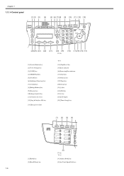
.../Data indicator [17] [Start] key [18] Numeric key [19] [Tone] key [20] [Clear] key [21] [+] key [22] [OK] key [23] [-] key [24] LCD display [25] [Toner Gauge] key [1] [2] [3] [4] Recall/Pause [1] [Hook] key [2] [Recall/Pause] key [5] F-1-6 T-1-2 [4] [Address Book] key [5] One-Touch Speed Dial keys 1-4
.../Data indicator [17] [Start] key [18] Numeric key [19] [Tone] key [20] [Clear] key [21] [+] key [22] [OK] key [23] [-] key [24] LCD display [25] [Toner Gauge] key [1] [2] [3] [4] Recall/Pause [1] [Hook] key [2] [Recall/Pause] key [5] F-1-6 T-1-2 [4] [Address Book] key [5] One-Touch Speed Dial keys 1-4
Service Manual
Page 24
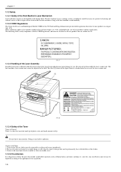
...local regulations. 1-6 CANON 30-2, SHIMOMARUKO, 3-CHOME, OHTAKU, TOKYO, 146, JAPAN. F-1-7 1.1.2.3 Handling of the Laser Assembly 0016-1805 Invisible laser beam is completely sealed by washing with vinyl must always be attached to all laser products that include combustible materials such as lithium battery and toner cartridge etc., into ... Devices and Radiological Health (CDRH) of the US Food and Drug Administrator put into fire. Do not throw toner into forth regulations that relate to laser products on August 2nd, 1976. The use of warm water must be avoided, doing so will not leak ...
...local regulations. 1-6 CANON 30-2, SHIMOMARUKO, 3-CHOME, OHTAKU, TOKYO, 146, JAPAN. F-1-7 1.1.2.3 Handling of the Laser Assembly 0016-1805 Invisible laser beam is completely sealed by washing with vinyl must always be attached to all laser products that include combustible materials such as lithium battery and toner cartridge etc., into ... Devices and Radiological Health (CDRH) of the US Food and Drug Administrator put into fire. Do not throw toner into forth regulations that relate to laser products on August 2nd, 1976. The use of warm water must be avoided, doing so will not leak ...
Service Manual
Page 25
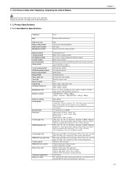
... method Exposure method Charging method Development method Transfer method Separation method Pickup method Cassette pickup method Multifeeder pickup method Drum cleaning method Fixing method Toner supply type Toner type Toner save mode Original type Maximum original size Reproduction ratio Reading resolution Printing resolution Warm-up to 2 kg) Fixed: 216mm x 297mm ADF: ... Continuous reproduction Energy save mode Fixed Desktop (ADF standard type) LED Contact Sensor Reading Method OPC drum Indirect electrostatic copying method Semiconductor laser Roller contact charging method Dry system -
... method Exposure method Charging method Development method Transfer method Separation method Pickup method Cassette pickup method Multifeeder pickup method Drum cleaning method Fixing method Toner supply type Toner type Toner save mode Original type Maximum original size Reproduction ratio Reading resolution Printing resolution Warm-up to 2 kg) Fixed: 216mm x 297mm ADF: ... Continuous reproduction Energy save mode Fixed Desktop (ADF standard type) LED Contact Sensor Reading Method OPC drum Indirect electrostatic copying method Semiconductor laser Roller contact charging method Dry system -
Service Manual
Page 26
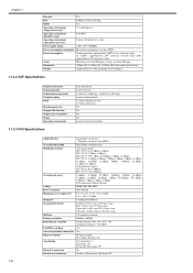
...) Ozone Maximum: less than 0.05 ppm, average: less than 0.02 ppm Dimensions 390mm (W) x 442mm (D) x 470mm (H) (with original pick-up tray) Weight Approximately 13.4kg (including toner cartridges) 1.1.3.2 ADF Specifications 0016-1762 Original orientation Original position Original processing mode Original reading Stack Mixed original sizes Original AE detection Original size recognition Stamp...
...) Ozone Maximum: less than 0.05 ppm, average: less than 0.02 ppm Dimensions 390mm (W) x 442mm (D) x 470mm (H) (with original pick-up tray) Weight Approximately 13.4kg (including toner cartridges) 1.1.3.2 ADF Specifications 0016-1762 Original orientation Original position Original processing mode Original reading Stack Mixed original sizes Original AE detection Original size recognition Stamp...

Service Manual
Page 35
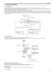
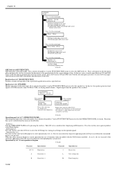
... of power supply INTR (initial rotation) Interval between the input of print command from the SCNT board and to transfer the toner image onto media LSTR (last rotation) Interval between turnon of the power supply and the end of the initial drive To ...operations of reader unit and the engine from the SCNT board, host machine enters INTR immediately after printing. System Control System Scanning Control System Laser / Scanner System Printer Control System Image Formation System Fixing System Pickup / Feeding System F-2-1 2.2 Basic Sequence 2.2.1 Basic Operation Sequence 0016-...
... of power supply INTR (initial rotation) Interval between the input of print command from the SCNT board and to transfer the toner image onto media LSTR (last rotation) Interval between turnon of the power supply and the end of the initial drive To ...operations of reader unit and the engine from the SCNT board, host machine enters INTR immediately after printing. System Control System Scanning Control System Laser / Scanner System Printer Control System Image Formation System Fixing System Pickup / Feeding System F-2-1 2.2 Basic Sequence 2.2.1 Basic Operation Sequence 0016-...

Service Manual
Page 67
Contents Contents 6.1 Overview/Configuration ...6-1 6.1.1 Configuration ...6-1 6.1.2 Print Process...6-1 6.2 Driving and Controlling the High-Voltage System ...6-3 6.2.1 Generation of Transfer Charging Bias ...6-3 6.3 Toner Cartridge ...6-3 6.3.1 Toner Level Detection ...6-3 6.4 Parts Replacement Procedure...6-4 6.4.1 Transfer Charging Roller ...6-4 6.4.1.1 Removing the Transfer Charging Roller...6-4
Contents Contents 6.1 Overview/Configuration ...6-1 6.1.1 Configuration ...6-1 6.1.2 Print Process...6-1 6.2 Driving and Controlling the High-Voltage System ...6-3 6.2.1 Generation of Transfer Charging Bias ...6-3 6.3 Toner Cartridge ...6-3 6.3.1 Toner Level Detection ...6-3 6.4 Parts Replacement Procedure...6-4 6.4.1 Transfer Charging Roller ...6-4 6.4.1.1 Removing the Transfer Charging Roller...6-4
Service Manual
Page 69
... into the permanent image on the paper when the heat and pressure are formed on the paper by the laser diode. The toner image is the outline of the blocks and steps of the print process. Primary charging 2. When receiving the print command from the SCNT ... 7. Drum cleaning Transfer block 5. The surface of the photosensitive drum is evenly charged negative by the primary charging roller, and the laser beam converted with the toner on the developing cylinder and is transferred on the photosensitive drum. Step1: Primary charging (Charges negative potential evenly on the surface of ...
... into the permanent image on the paper when the heat and pressure are formed on the paper by the laser diode. The toner image is the outline of the blocks and steps of the print process. Primary charging 2. When receiving the print command from the SCNT ... 7. Drum cleaning Transfer block 5. The surface of the photosensitive drum is evenly charged negative by the primary charging roller, and the laser beam converted with the toner on the developing cylinder and is transferred on the photosensitive drum. Step1: Primary charging (Charges negative potential evenly on the surface of ...

Service Manual
Page 70
Step 7: Drum cleaning (Removes the residual toner on the photosensitive drum is removed. Chapter 6 The toner image on the surface of the photosensitive drum is fixed on the paper. Step 4: Transfer (Transfers the toner on the photosensitive drum to a paper) Step 5: Separation (Separates the paper from the photosensitive drum) 4) Fixing block The toner image is transferred to papers. Step 6: Fixing 5) Drum cleaning block The residual toner on the photosensitive drum) 6-2
Step 7: Drum cleaning (Removes the residual toner on the photosensitive drum is removed. Chapter 6 The toner image on the surface of the photosensitive drum is fixed on the paper. Step 4: Transfer (Transfers the toner on the photosensitive drum to a paper) Step 5: Separation (Separates the paper from the photosensitive drum) 4) Fixing block The toner image is transferred to papers. Step 6: Fixing 5) Drum cleaning block The residual toner on the photosensitive drum) 6-2
Service Manual
Page 71
...- The following are transfer charging DC positive bias and transfer charging DC negative bias generated at the time of the toner sensor with the reference value, and detects the toner level. Chapter 6 6.2 Driving and Controlling the High-Voltage System 6.2.1 Generation of Transfer Charging Bias 0016-1841 The ...charging bias (TRS) is applied to the transfer charging roller. - Faint transfer charging DC positive bias is output to transfer the toner on the transfer charging roller to each print sequence. The transfer charging DC positive bias is made from magnetic body and resin into ...
...- The following are transfer charging DC positive bias and transfer charging DC negative bias generated at the time of the toner sensor with the reference value, and detects the toner level. Chapter 6 6.2 Driving and Controlling the High-Voltage System 6.2.1 Generation of Transfer Charging Bias 0016-1841 The ...charging bias (TRS) is applied to the transfer charging roller. - Faint transfer charging DC positive bias is output to transfer the toner on the transfer charging roller to each print sequence. The transfer charging DC positive bias is made from magnetic body and resin into ...
Service Manual
Page 87
... of the CPU (IC902). If the temperature of the fixing heater increases abnormally, it blocks power supply to inside of the fixing assembly, and the toner is deposited on the DCNT board with the fixing film and the pressure roller. By heating the fixing film with the fixing heater, it is...
... of the CPU (IC902). If the temperature of the fixing heater increases abnormally, it blocks power supply to inside of the fixing assembly, and the toner is deposited on the DCNT board with the fixing film and the pressure roller. By heating the fixing film with the fixing heater, it is...
Service Manual
Page 111
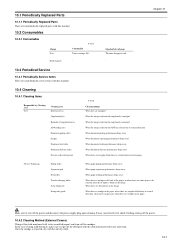
...-1 10.1 Periodically Replaced Parts 10.1.1 Periodically Replaced Parts There are no periodically service items with this machine. 10.2 Consumables 10.2.1 Consumable Charge User T-10-1 Consumable Toner cartridge 104 Field engineer - Chapter 10 0016-1869 0016-1871 10.3 Periodical Service 10.3.1 Periodically Service Items 0016-1875 There are no periodically replaced parts... smudge is removed, dry with water or mild detergent, and wipe off the detergent with the cloth moistened with water afterward. Standard of exchange The toner disappears and. -
...-1 10.1 Periodically Replaced Parts 10.1.1 Periodically Replaced Parts There are no periodically service items with this machine. 10.2 Consumables 10.2.1 Consumable Charge User T-10-1 Consumable Toner cartridge 104 Field engineer - Chapter 10 0016-1869 0016-1871 10.3 Periodical Service 10.3.1 Periodically Service Items 0016-1875 There are no periodically replaced parts... smudge is removed, dry with water or mild detergent, and wipe off the detergent with the cloth moistened with water afterward. Standard of exchange The toner disappears and. -
Service Manual
Page 124
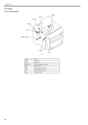
Chapter 12 12.1.2 Sensor 12.1.2.1 List of Sensors 0016-1914 PS106 PS105 PS804 PS803 SR1 PS801/PS802 PS805 F-12-2 TS101 Symbol PS105 PS106 PS801/PS802 PS803 PS804 PS805 SR1 TS101 Name DES sensor DS sensor leading edge/paper width sensor delivery sensor delivery paper width sensor Multi-purpose pickup sensor CS home position sensor Toner level sensor 12-2
Chapter 12 12.1.2 Sensor 12.1.2.1 List of Sensors 0016-1914 PS106 PS105 PS804 PS803 SR1 PS801/PS802 PS805 F-12-2 TS101 Symbol PS105 PS106 PS801/PS802 PS803 PS804 PS805 SR1 TS101 Name DES sensor DS sensor leading edge/paper width sensor delivery sensor delivery paper width sensor Multi-purpose pickup sensor CS home position sensor Toner level sensor 12-2
Service Manual
Page 172
... correspondence diagram T-14-24 Character Operation key Character Operation key 0-9,*,# Numeric key I Density key A Cursor key (+) L View settings key B Cursor key (-) M Toner Gauge key 14-32 In this test, enter a transfer speed between the ON and OFF states with the left and right cursor keys to select...menu. Chapter 14 6-3:SENOR [1] - [8] Press '1' on the numeric pad. CRG ON FCV ON ALS [of of of] CRG:Toner cartridge sensor: on/of FCV:Toner cartridge cover: on/of ALS:Multi-purpass paper sensor/Paper width sensor /Delivery sensor: on/of Press '3' on the numeric pad....
... correspondence diagram T-14-24 Character Operation key Character Operation key 0-9,*,# Numeric key I Density key A Cursor key (+) L View settings key B Cursor key (-) M Toner Gauge key 14-32 In this test, enter a transfer speed between the ON and OFF states with the left and right cursor keys to select...menu. Chapter 14 6-3:SENOR [1] - [8] Press '1' on the numeric pad. CRG ON FCV ON ALS [of of of] CRG:Toner cartridge sensor: on/of FCV:Toner cartridge cover: on/of ALS:Multi-purpass paper sensor/Paper width sensor /Delivery sensor: on/of Press '3' on the numeric pad....

Service Manual
Page 179
... number: CK-8007 Use a rag to fire. - Do not put close to clean the exterior of Use Component 1 Alcohol Cleaning E.g.) Plastics Rubber Metals Grease Buildup Toner Buildup Alcohols 2 Lubricating Oil - Apply to the gear Special oil - Molykote 41 (Produced by Dow Corning Corporation) -
... number: CK-8007 Use a rag to fire. - Do not put close to clean the exterior of Use Component 1 Alcohol Cleaning E.g.) Plastics Rubber Metals Grease Buildup Toner Buildup Alcohols 2 Lubricating Oil - Apply to the gear Special oil - Molykote 41 (Produced by Dow Corning Corporation) -


