
Service Manual
Page 5
2.3 Sensors...II-29 2.3.1 Cover Sensor...II-29 2.3.2 Toner Empty Sensor II-29 2.4 Drum Unit...II-30 2.4.1 Photosensitive Drum II-30 2.4.2 Primary Charger ...II-30 2.4.3 Developer Roller...II-30 2.4.4 Transfer Roller...II-30 2.4.5 Cleaner ...
2.3 Sensors...II-29 2.3.1 Cover Sensor...II-29 2.3.2 Toner Empty Sensor II-29 2.4 Drum Unit...II-30 2.4.1 Photosensitive Drum II-30 2.4.2 Primary Charger ...II-30 2.4.3 Developer Roller...II-30 2.4.4 Transfer Roller...II-30 2.4.5 Cleaner ...

Service Manual
Page 6
... Contacts IV-20 4. CONSUMABLE PARTS...IV-3 2.1 Drum Unit...IV-3 2.2 Toner Cartridge ...IV-3 2.3 Periodical Replacement Parts IV-3 3. Serial No. Descriptions ...A-1 2. Connection Diagram, HL-1050 A-4 5. Main PCB Circuit Diagram, (HL-820/1020/1040), (2/2 A-6 7. Main PCB Circuit Diagram, (HL-1050), (4/5 A-10 11. Low-voltage Power Supply PCB Circuit Diagram, HL-820/1020/1040 (110 - 120V) ........A-13 14. PAPER JAM ...IV...
... Contacts IV-20 4. CONSUMABLE PARTS...IV-3 2.1 Drum Unit...IV-3 2.2 Toner Cartridge ...IV-3 2.3 Periodical Replacement Parts IV-3 3. Serial No. Descriptions ...A-1 2. Connection Diagram, HL-1050 A-4 5. Main PCB Circuit Diagram, (HL-820/1020/1040), (2/2 A-6 7. Main PCB Circuit Diagram, (HL-1050), (4/5 A-10 11. Low-voltage Power Supply PCB Circuit Diagram, HL-820/1020/1040 (110 - 120V) ........A-13 14. PAPER JAM ...IV...
Service Manual
Page 7
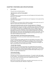
...When printing, an animated dialog box appears on the floppy disk and CD-ROM supplied with microfine toner and 8 pages per minute (ppm) printing speed (A4 or Letter paper). FEATURES This printer has the following features: High Resolution and Fast Printing Speed True 600 dots per inch (dpi... dpi for the corrective action to show the current status of paper, the dialog box will appear to let you to set various printer settings including toner saving mode, custom paper size, sleep mode, gray scale adjustment, resolution, and so forth. For example: when your custom paper size...
...When printing, an animated dialog box appears on the floppy disk and CD-ROM supplied with microfine toner and 8 pages per minute (ppm) printing speed (A4 or Letter paper). FEATURES This printer has the following features: High Resolution and Fast Printing Speed True 600 dots per inch (dpi... dpi for the corrective action to show the current status of paper, the dialog box will appear to let you to set various printer settings including toner saving mode, custom paper size, sleep mode, gray scale adjustment, resolution, and so forth. For example: when your custom paper size...

Service Manual
Page 8
... the 300 dpi resolution mode. When you use your printer with each toner cartridge may vary depending on . It can do it using the Remote Printer Console Program. Popular Printer Emulation Support (for HL-1050 only) High resolution control (HRC) technology provides clear and crisp printouts. The HL-1040 supports HP LaserJet IIP, Epson FX-850...
... the 300 dpi resolution mode. When you use your printer with each toner cartridge may vary depending on . It can do it using the Remote Printer Console Program. Popular Printer Emulation Support (for HL-1050 only) High resolution control (HRC) technology provides clear and crisp printouts. The HL-1040 supports HP LaserJet IIP, Epson FX-850...
Service Manual
Page 9
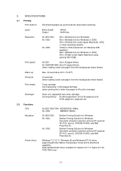
...EPSON FX-850, and IBM Proprinter XL Brother Printing Solution for HL1040/1050 only) I-3 SPECIFICATIONS 2.1 Printing Print method Electrophotography by semiconductor laser beam scanning Laser: Wave length: Output: 780nm 5mW max Resolution HL-820/1020: HL-1040: HL-1050: 600 x 600dots/inch (for ...toner cartridge Life Expectancy: 20,000 pages/drum unit at 20 pages per job 8,000 pages at 1 page per job 2.2 Functions CPU Emulation Printer driver HL-820/1020/1040: MC68EC000 16Mhz HL-1050: MB86831 66Mhz HL-820/1020: HL-1040: HL-1050: Brother Printing Solution for Windows Brother...
...EPSON FX-850, and IBM Proprinter XL Brother Printing Solution for HL1040/1050 only) I-3 SPECIFICATIONS 2.1 Printing Print method Electrophotography by semiconductor laser beam scanning Laser: Wave length: Output: 780nm 5mW max Resolution HL-820/1020: HL-1040: HL-1050: 600 x 600dots/inch (for ...toner cartridge Life Expectancy: 20,000 pages/drum unit at 20 pages per job 8,000 pages at 1 page per job 2.2 Functions CPU Emulation Printer driver HL-820/1020/1040: MC68EC000 16Mhz HL-1050: MB86831 66Mhz HL-820/1020: HL-1040: HL-1050: Brother Printing Solution for Windows Brother...

Service Manual
Page 10
... reference value and should be used inside the Brother offices only. The peak figure of power consumption is worked out excluding inrush current value. PR99017 Interface Memory Control panel Diagnostics Bi-directional parallel Universal Serial Bus (USB) (HL-1050 only) RS-422A/RS-232C serial (... Approx. 7.2kg (15.7lb.) including the drum unit and toner cartridge Note: The peak figure of power consumption is worked out when the halogen heater lamp is optionally available. (HL1040/1050 only) HL-820/1020/1040: 2.0 Mbytes HL-1050: 4.0 Mbytes Expandable up to 36 Mbytes by installing an...
... reference value and should be used inside the Brother offices only. The peak figure of power consumption is worked out excluding inrush current value. PR99017 Interface Memory Control panel Diagnostics Bi-directional parallel Universal Serial Bus (USB) (HL-1050 only) RS-422A/RS-232C serial (... Approx. 7.2kg (15.7lb.) including the drum unit and toner cartridge Note: The peak figure of power consumption is worked out when the halogen heater lamp is optionally available. (HL1040/1050 only) HL-820/1020/1040: 2.0 Mbytes HL-1050: 4.0 Mbytes Expandable up to 36 Mbytes by installing an...

Service Manual
Page 17
... Drive block (Stepping motor) Paper tray unit Paper tray Manual feed Developing block Drum Charging block Cleaner block Toner cartridge Image generation system Fig. 2-1 Fixing unit Paper eject block Paper feed system II-1 CHAPTER II THEORY OF OPERATION 1. ELECTRONICS 1.1 General Block Diagram HL-820/1020 Fig. 2-1 shows a general block diagram of the HL-820/1020 printer.
... Drive block (Stepping motor) Paper tray unit Paper tray Manual feed Developing block Drum Charging block Cleaner block Toner cartridge Image generation system Fig. 2-1 Fixing unit Paper eject block Paper feed system II-1 CHAPTER II THEORY OF OPERATION 1. ELECTRONICS 1.1 General Block Diagram HL-820/1020 Fig. 2-1 shows a general block diagram of the HL-820/1020 printer.

Service Manual
Page 18
...Low-voltage power supply block High-voltage power supply block Engine control block Operation block (Operation panel) Erase lamp Laser scanner unit Drum unit Transfer block Drive block (Stepping motor) Paper tray unit Paper tray Manual feed Developing block Drum Charging ...block Cleaner block Toner cartridge Image generation system Fig. 2-2 Fixing unit Paper eject block Paper feed system II-2 RS-232C) Expansion I /F board (Mac. External device HL-1040 Fig. 2-2 shows a general block diagram of the HL-1040 printer.
...Low-voltage power supply block High-voltage power supply block Engine control block Operation block (Operation panel) Erase lamp Laser scanner unit Drum unit Transfer block Drive block (Stepping motor) Paper tray unit Paper tray Manual feed Developing block Drum Charging ...block Cleaner block Toner cartridge Image generation system Fig. 2-2 Fixing unit Paper eject block Paper feed system II-2 RS-232C) Expansion I /F board (Mac. External device HL-1040 Fig. 2-2 shows a general block diagram of the HL-1040 printer.

Service Manual
Page 19
...voltage power supply block High-voltage power supply block Engine control block Operation block (Operation panel) Erase lamp Laser scanner unit Drum unit Transfer block Drive block (Stepping motor) Paper tray unit Paper tray Manual feed Developing block Drum ...Charging block Cleaner block Toner cartridge Image generation system Fig. 2-3 Fixing unit Paper eject block Paper feed system II-3 RS-232C) Control system Expansion memory I/O Expansion I /F board (Mac. External device HL-1050 Fig. 2-3 shows a general block diagram of the HL-1050 printer.
...voltage power supply block High-voltage power supply block Engine control block Operation block (Operation panel) Erase lamp Laser scanner unit Drum unit Transfer block Drive block (Stepping motor) Paper tray unit Paper tray Manual feed Developing block Drum ...Charging block Cleaner block Toner cartridge Image generation system Fig. 2-3 Fixing unit Paper eject block Paper feed system II-3 RS-232C) Control system Expansion memory I/O Expansion I /F board (Mac. External device HL-1050 Fig. 2-3 shows a general block diagram of the HL-1050 printer.

Service Manual
Page 40
Model HL-820/1020/1040 HL-1050 Regulated Output +5V / 0.6 A +24V / 2.0 A +5V / 1.2A +24V / ...• Control Panel 1 Switch, 4 lamps • Connector Low-voltage, high-voltage, solenoid, main motor, toner sensor, laser, polygon motor, connector for main PCB • Registration sensor 1.5 Power Supply 1.5.1 Low-voltage Power Supply The ...power supply uses a switching regulation system to generate the regulated DC power (+5V and +24V), which are on the printer...
Model HL-820/1020/1040 HL-1050 Regulated Output +5V / 0.6 A +24V / 2.0 A +5V / 1.2A +24V / ...• Control Panel 1 Switch, 4 lamps • Connector Low-voltage, high-voltage, solenoid, main motor, toner sensor, laser, polygon motor, connector for main PCB • Registration sensor 1.5 Power Supply 1.5.1 Low-voltage Power Supply The ...power supply uses a switching regulation system to generate the regulated DC power (+5V and +24V), which are on the printer...

Service Manual
Page 42
... Registration Sensor Lever Paper Feed Roller Drum Unit Pinch Roller Blade Photosensitive Drum Transfer Roller Erase Lamp Fixing Unit Pressure Roller Eject Roller Toner Cartridge Polygon Mirror Toner Empty Laser Scanner Sensor Supply Roller Eject Sensor Actuator Heat Roller Development Thermistor Roller Cleaning Roller Corona Wire Scanner Unit Fig. 2-29 Main Cotrol PCB...
... Registration Sensor Lever Paper Feed Roller Drum Unit Pinch Roller Blade Photosensitive Drum Transfer Roller Erase Lamp Fixing Unit Pressure Roller Eject Roller Toner Cartridge Polygon Mirror Toner Empty Laser Scanner Sensor Supply Roller Eject Sensor Actuator Heat Roller Development Thermistor Roller Cleaning Roller Corona Wire Scanner Unit Fig. 2-29 Main Cotrol PCB...

Service Manual
Page 45
Toner Empty Sensor Fig. 2-36 II-29 Top Cover Cover Switch Fig. 2-35 2.3.2 Toner Empty Sensor Detects if there is installed in the toner cartridge. It also detects whether or not the drum unit is installed. (The toner cartridge is toner in the drum unit). 2.3 Sensors 2.3.1 Cover Sensor Detects opening and closing of the top cover.
Toner Empty Sensor Fig. 2-36 II-29 Top Cover Cover Switch Fig. 2-35 2.3.2 Toner Empty Sensor Detects if there is installed in the toner cartridge. It also detects whether or not the drum unit is installed. (The toner cartridge is toner in the drum unit). 2.3 Sensors 2.3.1 Cover Sensor Detects opening and closing of the top cover.

Service Manual
Page 46
II-30 Applicable safety standards have been complied with the negatively charged drum. The level of ozone expelled from the printer is therefore not harmful to approx. 280V by the voltage regulator. 280V Passive Type Voltage Regulator Voltage Regulator +++-+-- -- - ++ 1150V - + -- - ++ - + ++ +... electrostatic image on the drum surface by the addition of the toner. 2.4.4 Transfer Roller Transfers the toner image to the paper from the drum surface. 2.4.5 Cleaner Roller Removes and recycles the toner remaining on the drum surface. 2.4.6 Erase Lamp Discharges the electrostatic...
II-30 Applicable safety standards have been complied with the negatively charged drum. The level of ozone expelled from the printer is therefore not harmful to approx. 280V by the voltage regulator. 280V Passive Type Voltage Regulator Voltage Regulator +++-+-- -- - ++ 1150V - + -- - ++ - + ++ +... electrostatic image on the drum surface by the addition of the toner. 2.4.4 Transfer Roller Transfers the toner image to the paper from the drum surface. 2.4.5 Cleaner Roller Removes and recycles the toner remaining on the drum surface. 2.4.6 Erase Lamp Discharges the electrostatic...

Service Manual
Page 48
...the development roller and the drum and developed onto the latent image on the drum. Blade Transfer roller (a) Transfer process [ON] Separator Toner (b) Cleaning process [ON] Auger Develop housing Drum Erase lamp (a) Collecting process Supply roller DC-bias SR-bias Development roller Fig. 2-40 (b)...process of conductive rubber and the supply roller (which will adhere to the transfer roller. The developer consists of the drum. The toner adheres to the development roller and is nipped between the drum and the development roller, which is transferred onto the paper by applying ...
...the development roller and the drum and developed onto the latent image on the drum. Blade Transfer roller (a) Transfer process [ON] Separator Toner (b) Cleaning process [ON] Auger Develop housing Drum Erase lamp (a) Collecting process Supply roller DC-bias SR-bias Development roller Fig. 2-40 (b)...process of conductive rubber and the supply roller (which will adhere to the transfer roller. The developer consists of the drum. The toner adheres to the development roller and is nipped between the drum and the development roller, which is transferred onto the paper by applying ...

Service Manual
Page 49
..., ready to receive a uniform charge in the fixing unit. 2.5.5 Drum Cleaning Stage In the image transfer stage, not all the toner on the photosensitive drum is transferred onto the paper but some remains on or off the halogen heater lamp. In the drum cleaning stage... primary charging stage. 2.5.7 Fixing Stage The image transferred to the paper by static electricity is fixed by the cleaning roller, so that residual toner on the drum surface is exposed to the drum during starting or non-printing time. Pressure roller Thermistor ASSY Halogen heater lamp ,,,,,,,,,, Heat roller...
..., ready to receive a uniform charge in the fixing unit. 2.5.5 Drum Cleaning Stage In the image transfer stage, not all the toner on the photosensitive drum is transferred onto the paper but some remains on or off the halogen heater lamp. In the drum cleaning stage... primary charging stage. 2.5.7 Fixing Stage The image transferred to the paper by static electricity is fixed by the cleaning roller, so that residual toner on the drum surface is exposed to the drum during starting or non-printing time. Pressure roller Thermistor ASSY Halogen heater lamp ,,,,,,,,,, Heat roller...

Service Manual
Page 58
If there is any dirt or dust on the mirror, blow it off. Ferrite Core Cable binder Flat cable LD harness Fig. 3-13 (3) Disconnect the three connectors from the panel sensor PCB. (4) Remove the M3x8 tapping screw, and lift the toner sensor PCB from the scanner unit. Taptite, cup M3x8 Toner Sensor PCB Fig. 3-14 Scanner Unit III-9 Note: When replacing the scanner unit, ensure to assemble the ferrite core using the cable binder as follows; Caution: Never touch the inside of the scanner unit or the mirror when disassembling or reassembling.
If there is any dirt or dust on the mirror, blow it off. Ferrite Core Cable binder Flat cable LD harness Fig. 3-13 (3) Disconnect the three connectors from the panel sensor PCB. (4) Remove the M3x8 tapping screw, and lift the toner sensor PCB from the scanner unit. Taptite, cup M3x8 Toner Sensor PCB Fig. 3-14 Scanner Unit III-9 Note: When replacing the scanner unit, ensure to assemble the ferrite core using the cable binder as follows; Caution: Never touch the inside of the scanner unit or the mirror when disassembling or reassembling.

Service Manual
Page 61
... must be inserted securely into the PCB connectors and the PCB must not be inserted by the harnesses. Solenoid harness 7. Low-voltage harness 2. Laser harness 6. (3) Disconnect the eight connectors from the PCB. (Three connectors have already been disconnected when removing the scanner unit.) Panel Sensor PCB ...the LV harness from the PCB. The connectors should be stressed by matching the housing color and the number of the Harnesses) 1. Toner harness 4. Fan motor 2 harness 10. Main / sub motor connector 8. Low-voltage Power Supply ASSY H r h rn LV harness Fig...
... must be inserted securely into the PCB connectors and the PCB must not be inserted by the harnesses. Solenoid harness 7. Low-voltage harness 2. Laser harness 6. (3) Disconnect the eight connectors from the PCB. (Three connectors have already been disconnected when removing the scanner unit.) Panel Sensor PCB ...the LV harness from the PCB. The connectors should be stressed by matching the housing color and the number of the Harnesses) 1. Toner harness 4. Fan motor 2 harness 10. Main / sub motor connector 8. Low-voltage Power Supply ASSY H r h rn LV harness Fig...
Service Manual
Page 68
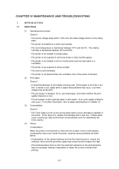
...printouts, take out the drum unit and slowly rock it impossible to redistribute the toner evenly.] (4) Others Condensation: When the printer is moved from the rated voltage shown on the rating plate. • The printer is installed on a solid, level surface. • The room temperature is ... The source voltage stays within ±10% from a cold room into a warm room in the printer. [If the lamp is installed in cold weather, condensation may occur inside the printer, causing various problems as the scanning mirror, lenses, the reflection mirror and the protection glass may occur...
...printouts, take out the drum unit and slowly rock it impossible to redistribute the toner evenly.] (4) Others Condensation: When the printer is moved from the rated voltage shown on the rating plate. • The printer is installed on a solid, level surface. • The room temperature is ... The source voltage stays within ±10% from a cold room into a warm room in the printer. [If the lamp is installed in cold weather, condensation may occur inside the printer, causing various problems as the scanning mirror, lenses, the reflection mirror and the protection glass may occur...

Service Manual
Page 70
... once every five seconds. The Data and Alarm lamps blink once every second. 2,400 pages/new toner cartridge (when printing A4- IV-3 CONSUMABLE PARTS 2.1 Drum Unit The Drum lamp is nearly at 5% print coverage) Note: Toner life expectancy will vary depending on when the drum unit is on the type of prints... Unit 3 MP sheet feeder ASSY Part No. They are many factors that determine the actual drum life, such as temperature, humidity, type of paper and toner that you use, the number of its life. or letter-size paper at the end of pages per job Note: There are subject to change...
... once every five seconds. The Data and Alarm lamps blink once every second. 2,400 pages/new toner cartridge (when printing A4- IV-3 CONSUMABLE PARTS 2.1 Drum Unit The Drum lamp is nearly at 5% print coverage) Note: Toner life expectancy will vary depending on when the drum unit is on the type of prints... Unit 3 MP sheet feeder ASSY Part No. They are many factors that determine the actual drum life, such as temperature, humidity, type of paper and toner that you use, the number of its life. or letter-size paper at the end of pages per job Note: There are subject to change...

Service Manual
Page 72
... with the drum unit removed? Check if the toner sensor needs cleaning and check the toner sensor connection. Replace the toner cartridge. If the connection is installed? I-1 Light Possible cause Toner sensing failure (printer side) Toner sensing failure (toner cartridge side) Drum connection failure High-voltage power ...printing on the drum unit. When using the printer for information about the location of the toner cartridge is used. Result Yes Yes No No No Yes Remedy Toner sensor failure. Clean contact electrodes both in the printer body and on one ? Replace the panel ...
... with the drum unit removed? Check if the toner sensor needs cleaning and check the toner sensor connection. Replace the toner cartridge. If the connection is installed? I-1 Light Possible cause Toner sensing failure (printer side) Toner sensing failure (toner cartridge side) Drum connection failure High-voltage power ...printing on the drum unit. When using the printer for information about the location of the toner cartridge is used. Result Yes Yes No No No Yes Remedy Toner sensor failure. Clean contact electrodes both in the printer body and on one ? Replace the panel ...


