Service Manual
Page 3
...and service information bulletins, is vital to the service technician to find the cause of the laser printer (here- This service manual covers the HL-820, 1020, 1040 and 1050 laser printers. (Note that any figures for after referred to as "this manual is subject to ...electrical circuits, and their timing information. APPENDICES :SERIAL NO. All relevant information in such cases will be supplied in this printer, based on the HL-1040 printer.) This manual consists of the following chapters: CHAPTER I : FEATURES AND SPECIFICATIONS Features, specifications, etc. CHAPTER IV : ...
...and service information bulletins, is vital to the service technician to find the cause of the laser printer (here- This service manual covers the HL-820, 1020, 1040 and 1050 laser printers. (Note that any figures for after referred to as "this manual is subject to ...electrical circuits, and their timing information. APPENDICES :SERIAL NO. All relevant information in such cases will be supplied in this printer, based on the HL-1040 printer.) This manual consists of the following chapters: CHAPTER I : FEATURES AND SPECIFICATIONS Features, specifications, etc. CHAPTER IV : ...
Service Manual
Page 7
...dots per inch (dpi) with your Windows system using bi-directional parallel communications. The driver supports our unique compression mode to set various printer settings including toner saving mode, custom paper size, sleep mode, gray scale adjustment, resolution, and so forth. When printing, an ...sizes of paper, and various types of paper, the dialog box will appear to let you can easily install them into your printer. The printer consumes less than 13W when in use labels and transparencies. You can monitor your custom paper size. If an error occurs,...
...dots per inch (dpi) with your Windows system using bi-directional parallel communications. The driver supports our unique compression mode to set various printer settings including toner saving mode, custom paper size, sleep mode, gray scale adjustment, resolution, and so forth. When printing, an ...sizes of paper, and various types of paper, the dialog box will appear to let you can easily install them into your printer. The printer consumes less than 13W when in use labels and transparencies. You can monitor your custom paper size. If an error occurs,...

Service Manual
Page 8
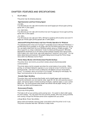
... function to Apple Macintosh computers. High Resolution Control & Advanced Photoscale Technology (for HL-1040/1050 only) These printers support the following printer emulation modes; I-2 Optional Apple Macintosh® Interface (for HL-1050 only) The Universal Serial Bus Interface is a Terminate-and-Stay Resident (... Low Running Cost The toner cartridge is available on the floppy disk and CD-ROM supplied with your printer. Popular Printer Emulation Support (for HL-1050 only) High resolution control (HRC) technology provides clear and crisp printouts. When you operate your ...
... function to Apple Macintosh computers. High Resolution Control & Advanced Photoscale Technology (for HL-1040/1050 only) These printers support the following printer emulation modes; I-2 Optional Apple Macintosh® Interface (for HL-1050 only) The Universal Serial Bus Interface is a Terminate-and-Stay Resident (... Low Running Cost The toner cartridge is available on the floppy disk and CD-ROM supplied with your printer. Popular Printer Emulation Support (for HL-1050 only) High resolution control (HRC) technology provides clear and crisp printouts. When you operate your ...
Service Manual
Page 9
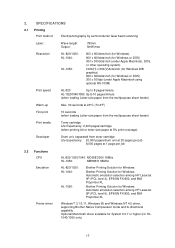
2. SPECIFICATIONS 2.1 Printing Print method Electrophotography by semiconductor laser beam scanning Laser: Wave length: Output: 780nm 5mW max Resolution HL-820/1020: HL-1040: HL-1050: 600 x 600dots/inch (for Windows) 600 x 600dots/inch (for Windows or DOS) 300 x 300dots/inch ... per job 8,000 pages at 1 page per job 2.2 Functions CPU Emulation Printer driver HL-820/1020/1040: MC68EC000 16Mhz HL-1050: MB86831 66Mhz HL-820/1020: HL-1040: HL-1050: Brother Printing Solution for Windows Brother Printing Solution for Windows Automatic emulation selection among HP LaserJet IIP (PCL level ...
2. SPECIFICATIONS 2.1 Printing Print method Electrophotography by semiconductor laser beam scanning Laser: Wave length: Output: 780nm 5mW max Resolution HL-820/1020: HL-1040: HL-1050: 600 x 600dots/inch (for Windows) 600 x 600dots/inch (for Windows or DOS) 300 x 300dots/inch ... per job 8,000 pages at 1 page per job 2.2 Functions CPU Emulation Printer driver HL-820/1020/1040: MC68EC000 16Mhz HL-1050: MB86831 66Mhz HL-820/1020: HL-1040: HL-1050: Brother Printing Solution for Windows Brother Printing Solution for Windows Automatic emulation selection among HP LaserJet IIP (PCL level ...

Service Manual
Page 12
... the paper. If short-grained paper is recommended to use acid paper to avoid any damage to the printer drum unit. (2) Paper feed conditions Type Name 60 to 250 (Sheffield) Caution: Although the printer can handle 9 inches (229mm) width paper such as the C4 size envelope, you may get stains on the...
... the paper. If short-grained paper is recommended to use acid paper to avoid any damage to the printer drum unit. (2) Paper feed conditions Type Name 60 to 250 (Sheffield) Caution: Although the printer can handle 9 inches (229mm) width paper such as the C4 size envelope, you may get stains on the...

Service Manual
Page 14
... dots) 6.01mm 0.24" (71 dots) 4.23mm 0.17" (50 dots) (Note that the paper sizes indicated here should conform to the nominal dimensions specified by any printer emulations (commands). The dot size is not supported by JIS.) A4 paper must accommodate 80 characters printed in pica pitch (203.2 mm).
... dots) 6.01mm 0.24" (71 dots) 4.23mm 0.17" (50 dots) (Note that the paper sizes indicated here should conform to the nominal dimensions specified by any printer emulations (commands). The dot size is not supported by JIS.) A4 paper must accommodate 80 characters printed in pica pitch (203.2 mm).

Service Manual
Page 15
... with FDA radiation performance standards, 21 CFR Subchapter J. This means that the printer does not produce hazardous laser radiation. The label for Japanese manufactured products MANUFACTURED: K BROTHER INDUSTRIES, LTD. 15-1, Naeshiro-cho, Mizuho-ku, Nagoya 467-8561, Japan. I-9 3. One of the printer indicates compliance with the FDA regulations and must be attached to the...
... with FDA radiation performance standards, 21 CFR Subchapter J. This means that the printer does not produce hazardous laser radiation. The label for Japanese manufactured products MANUFACTURED: K BROTHER INDUSTRIES, LTD. 15-1, Naeshiro-cho, Mizuho-ku, Nagoya 467-8561, Japan. I-9 3. One of the printer indicates compliance with the FDA regulations and must be attached to the...

Service Manual
Page 17
ELECTRONICS 1.1 General Block Diagram HL-820/1020 Fig. 2-1 shows a general block diagram of the HL-820/1020 printer. CHAPTER II THEORY OF OPERATION 1. Control system Video control block Interface block External device Low-voltage power supply block High-voltage power supply block Engine control block Operation block (Operation panel) Erase lamp Laser scanner unit Drum unit Transfer...
ELECTRONICS 1.1 General Block Diagram HL-820/1020 Fig. 2-1 shows a general block diagram of the HL-820/1020 printer. CHAPTER II THEORY OF OPERATION 1. Control system Video control block Interface block External device Low-voltage power supply block High-voltage power supply block Engine control block Operation block (Operation panel) Erase lamp Laser scanner unit Drum unit Transfer...

Service Manual
Page 18
... Fig. 2-2 shows a general block diagram of the HL-1040 printer. RS-232C) Expansion I /F board (Mac. Control system Optional I /O Video control block Interface block External device Low-voltage power supply block High-voltage power supply block Engine control block Operation block (Operation panel) Erase lamp Laser scanner unit Drum unit Transfer block Drive block...
... Fig. 2-2 shows a general block diagram of the HL-1040 printer. RS-232C) Expansion I /F board (Mac. Control system Optional I /O Video control block Interface block External device Low-voltage power supply block High-voltage power supply block Engine control block Operation block (Operation panel) Erase lamp Laser scanner unit Drum unit Transfer block Drive block...

Service Manual
Page 19
... control block Interface block External device Low-voltage power supply block High-voltage power supply block Engine control block Operation block (Operation panel) Erase lamp Laser scanner unit Drum unit Transfer block Drive block (Stepping motor) Paper tray unit Paper tray Manual feed Developing block Drum Charging block Cleaner block Toner...
... control block Interface block External device Low-voltage power supply block High-voltage power supply block Engine control block Operation block (Operation panel) Erase lamp Laser scanner unit Drum unit Transfer block Drive block (Stepping motor) Paper tray unit Paper tray Manual feed Developing block Drum Charging block Cleaner block Toner...

Service Manual
Page 40
..., main motor, toner sensor, laser, polygon motor, connector for main PCB • Registration sensor 1.5 Power Supply 1.5.1 Low-voltage Power Supply The power supply uses a switching regulation system to generate the regulated DC power (+5V and +24V), which are on the printer model as listed below; Model HL-820/1020/1040 HL-1050 Regulated Output +5V...
..., main motor, toner sensor, laser, polygon motor, connector for main PCB • Registration sensor 1.5 Power Supply 1.5.1 Low-voltage Power Supply The power supply uses a switching regulation system to generate the regulated DC power (+5V and +24V), which are on the printer model as listed below; Model HL-820/1020/1040 HL-1050 Regulated Output +5V...

Service Manual
Page 46
The level of ozone expelled from the printer is therefore not harmful to approx. 280V by the voltage regulator. 280V Passive Type Voltage Regulator Voltage Regulator +++-+-- -- - ++ 1150V - + -- - ++ - + ++ + + + + + ++ + + Corona wire Aluminum drum sleeve Organic ...
The level of ozone expelled from the printer is therefore not harmful to approx. 280V by the voltage regulator. 280V Passive Type Voltage Regulator Voltage Regulator +++-+-- -- - ++ 1150V - + -- - ++ - + ++ + + + + + ++ + + Corona wire Aluminum drum sleeve Organic ...

Service Manual
Page 50
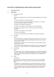
... disconnecting cable connectors, hold the connector body, not the cables. Also check that other related portions are functioning properly before accessing any parts inside the printer. (2) Be careful not to lose screws, washers, or other parts removed. (3) Be sure to apply grease to the gears and applicable positions specified in this...
... disconnecting cable connectors, hold the connector body, not the cables. Also check that other related portions are functioning properly before accessing any parts inside the printer. (2) Be careful not to lose screws, washers, or other parts removed. (3) Be sure to apply grease to the gears and applicable positions specified in this...

Service Manual
Page 56
... figure. Then, remove the pinch spring from the heat roller. The heat roller for HL-1060/1070 printers. PR98292 (5) Release the right side of the bearing is very similar to the one for the HL-820/1020/1040/1050 printers can be distinguished by the groove on the edge of the halogen heater lamp and...
... figure. Then, remove the pinch spring from the heat roller. The heat roller for HL-1060/1070 printers. PR98292 (5) Release the right side of the bearing is very similar to the one for the HL-820/1020/1040/1050 printers can be distinguished by the groove on the edge of the halogen heater lamp and...

Service Manual
Page 59
Taptite, bind M4x12 Taptite, cup M3x6 Taptite, bind M4x12 Taptite, cup M3x6 Taptite, bind M4x12 Base plate ASSY Taptite, bind M4x12 Fig. 3-16 III-10 Screw, pan M4x6 Hook Screw, pan M4x6 Fig. 3-15 Main PCB ASSY Hook 3.9 Base Plate ASSY Caution: Prior to pull out the main PCB ASSY. 3.8 Main PCB ASSY (1) Remove the three M4x6 screws. (2) Hold the hooks at the left and right of the mounting frame to turning the printer upside-down, ensure that the drum unit has been removed from the printer. (1) Turn the printer upside down. (2) Remove the eight M4 and five M3 self tapping screws.
Taptite, bind M4x12 Taptite, cup M3x6 Taptite, bind M4x12 Taptite, cup M3x6 Taptite, bind M4x12 Base plate ASSY Taptite, bind M4x12 Fig. 3-16 III-10 Screw, pan M4x6 Hook Screw, pan M4x6 Fig. 3-15 Main PCB ASSY Hook 3.9 Base Plate ASSY Caution: Prior to pull out the main PCB ASSY. 3.8 Main PCB ASSY (1) Remove the three M4x6 screws. (2) Hold the hooks at the left and right of the mounting frame to turning the printer upside-down, ensure that the drum unit has been removed from the printer. (1) Turn the printer upside down. (2) Remove the eight M4 and five M3 self tapping screws.

Service Manual
Page 63
Fan motor holder Taptite, bind M4x12 Taptite, bind M4x12 Fan Motor Manufacturer sticker side Main frame Fig. 3-24 III-14 3.13 Sub Fan Motor ASSY (1) Slide the sub fan motor ASSY upwards. Sub Fan Motor Manufacturer sticker side Main Cover Fig. 3-23 Note: When re-assembling the sub fan motor, ensure that the side on which the manufacturers sticker is attached is facing the main frame. 3.14 Main Fan Motor ASSY (1) Remove the two M4x12 screws securing the fan motor holder. (2) Remove the fan motor holder from the printer. (3) Remove the main fan motor from the fan motor holder.
Fan motor holder Taptite, bind M4x12 Taptite, bind M4x12 Fan Motor Manufacturer sticker side Main frame Fig. 3-24 III-14 3.13 Sub Fan Motor ASSY (1) Slide the sub fan motor ASSY upwards. Sub Fan Motor Manufacturer sticker side Main Cover Fig. 3-23 Note: When re-assembling the sub fan motor, ensure that the side on which the manufacturers sticker is attached is facing the main frame. 3.14 Main Fan Motor ASSY (1) Remove the two M4x12 screws securing the fan motor holder. (2) Remove the fan motor holder from the printer. (3) Remove the main fan motor from the fan motor holder.
Service Manual
Page 68
...so, print quality problems may cause the print image to ammonia fumes or other harmful gases. • The printer is not located in cold weather, condensation may occur inside the printer, causing various problems as listed below: • Condensation on printouts, take out the drum unit and slowly ...the print quality improves or not.] • The print paper is maintained between 20% and 80%. • The printer is not located in a dusty place. • The printer is not exposed to be light. • If the photosensitive drum is cold, the electrical resistance of the photosensitive layer...
...so, print quality problems may cause the print image to ammonia fumes or other harmful gases. • The printer is not located in cold weather, condensation may occur inside the printer, causing various problems as listed below: • Condensation on printouts, take out the drum unit and slowly ...the print quality improves or not.] • The print paper is maintained between 20% and 80%. • The printer is not located in a dusty place. • The printer is not exposed to be light. • If the photosensitive drum is cold, the electrical resistance of the photosensitive layer...

Service Manual
Page 72
... full one area of the paper continuously even though Letter or A4-size paper is installed? I-1 Light Possible cause Toner sensing failure (printer side) Toner sensing failure (toner cartridge side) Drum connection failure High-voltage power supply PCB failure Panel sensor PCB or main PCB failure ... connection is defective. Replace the panel sensor PCB or the main PCB. HV.GND contacts (Fig.4-5) ➀ IV-5 When using the printer for information about the location of the toner cartridge is normal, replace the high-voltage power supply PCB. Check the harness connection between the...
... full one area of the paper continuously even though Letter or A4-size paper is installed? I-1 Light Possible cause Toner sensing failure (printer side) Toner sensing failure (toner cartridge side) Drum connection failure High-voltage power supply PCB failure Panel sensor PCB or main PCB failure ... connection is defective. Replace the panel sensor PCB or the main PCB. HV.GND contacts (Fig.4-5) ➀ IV-5 When using the printer for information about the location of the toner cartridge is normal, replace the high-voltage power supply PCB. Check the harness connection between the...

Service Manual
Page 73
... dirty? Are there any disconnected connectors? Replace the highvoltage power supply PCB. HV.GND contacts (Fig.4-5) ➇ ➅ IV-6 Are the corona electrodes between the printer body and drum unit dirty? Is the problem solved when the drum unit is replaced? Replace the drum unit with a new one. Replace the main...
... dirty? Are there any disconnected connectors? Replace the highvoltage power supply PCB. HV.GND contacts (Fig.4-5) ➇ ➅ IV-6 Are the corona electrodes between the printer body and drum unit dirty? Is the problem solved when the drum unit is replaced? Replace the drum unit with a new one. Replace the main...

Service Manual
Page 74
... the shaft and the electrode. No Replace the highvoltage power supply PCB. No Check the connection between the printer body and drum unit dirty? 2 Are the drum shaft and drum electrode of the printer body connected correctly? 3 Is the problem solved after the main PCB or the panel sensor PCB replaced? 6 Scanner...
... the shaft and the electrode. No Replace the highvoltage power supply PCB. No Check the connection between the printer body and drum unit dirty? 2 Are the drum shaft and drum electrode of the printer body connected correctly? 3 Is the problem solved after the main PCB or the panel sensor PCB replaced? 6 Scanner...


