
Users Manual - English
Page 115
.... CHAPTER 5 MAINTENANCE The following are displayed: LCD Operator Call Message REPLACE FCR !" READY Fusing unit Drum Cleaner, Paper Discharger, Transfer Roller, Paper Pickup Roller Separator Pad, Transfer Drum Waste Toner Pack Oil Bottle Approximate Life 12,000 pages *1 60,000 images (Continuously printed) *4 ...60,000 pages *1 120,000 pages 18,000 Images 12,000 pages How to Replace Fuser Cleaner OPC Belt Cartridge REPLACE FUSER !" READY REPLACE OPC BELT !" READY...
.... CHAPTER 5 MAINTENANCE The following are displayed: LCD Operator Call Message REPLACE FCR !" READY Fusing unit Drum Cleaner, Paper Discharger, Transfer Roller, Paper Pickup Roller Separator Pad, Transfer Drum Waste Toner Pack Oil Bottle Approximate Life 12,000 pages *1 60,000 images (Continuously printed) *4 ...60,000 pages *1 120,000 pages 18,000 Images 12,000 pages How to Replace Fuser Cleaner OPC Belt Cartridge REPLACE FUSER !" READY REPLACE OPC BELT !" READY...

Users Manual - English
Page 182
...MEESSSSAAGGEESS Error Message ! ! K: Black, C: Cyan, M: Magenta, Y: Yellow. indicator disappears completely. It is nearly empty. Replace the OPC Belt Cartridge. It is time to replace the OPC Belt Cartridge. It is time to replace the Paper Feeding Kit 2. Replace the Oil Bottle. Replace the Fusing Unit. It is... Drum. mark blinks ("), the indicated color toner is almost empty. Replace it when the toner becomes empty. The Oil in the Oil Bottle is nearly empty. The Waste Toner Pack is time to replace the Cleaning Roller. " ! (K C M Y) FUSER OIL LOW REPLACE FCR REPLACE OPC ...
...MEESSSSAAGGEESS Error Message ! ! K: Black, C: Cyan, M: Magenta, Y: Yellow. indicator disappears completely. It is nearly empty. Replace the OPC Belt Cartridge. It is time to replace the OPC Belt Cartridge. It is time to replace the Paper Feeding Kit 2. Replace the Oil Bottle. Replace the Fusing Unit. It is... Drum. mark blinks ("), the indicated color toner is almost empty. Replace it when the toner becomes empty. The Oil in the Oil Bottle is nearly empty. The Waste Toner Pack is time to replace the Cleaning Roller. " ! (K C M Y) FUSER OIL LOW REPLACE FCR REPLACE OPC ...

Service Manual
Page 5
... 2. VIDEO CONTROLLER MODE V-2 2.1 Configuration of Normal Mode V-11 3.3 Service Mode ...V-18 3.4 Adjustment Work Procedures V-41 CHAPTER VI PERIODIC MAINTENANCE VI-1 1. PERIODIC MAINTENANCE PROCEDURES VI-20 2.1 OPC Belt Cartridge Replacement VI-20 2.2 Fusing Unit Replacement VI-23 2.3 Transfer Roller 2 Replacement VI-27 2.4 Paper Discharger Unit Replacement VI-30...
... 2. VIDEO CONTROLLER MODE V-2 2.1 Configuration of Normal Mode V-11 3.3 Service Mode ...V-18 3.4 Adjustment Work Procedures V-41 CHAPTER VI PERIODIC MAINTENANCE VI-1 1. PERIODIC MAINTENANCE PROCEDURES VI-20 2.1 OPC Belt Cartridge Replacement VI-20 2.2 Fusing Unit Replacement VI-23 2.3 Transfer Roller 2 Replacement VI-27 2.4 Paper Discharger Unit Replacement VI-30...
Service Manual
Page 23
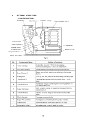
... the paper correctly ready for separating the paper from the OPC belt on the transfer drum 2 to the paper. Feeds paper automatically from the transfer drum 2 to the transfer drum 2. Fixes by heat and pressure the toner image onto the paper. INTERNAL STRUCTURE 4.Fusing Unit 3.Drum Cleaner 2 2.OPC Belt Cartridge 1.Toner Cartridge (K, Y, M, C) 5.Transfer Unit 2 7.Paper Discharger 8.Transfer...
... the paper correctly ready for separating the paper from the OPC belt on the transfer drum 2 to the paper. Feeds paper automatically from the transfer drum 2 to the transfer drum 2. Fixes by heat and pressure the toner image onto the paper. INTERNAL STRUCTURE 4.Fusing Unit 3.Drum Cleaner 2 2.OPC Belt Cartridge 1.Toner Cartridge (K, Y, M, C) 5.Transfer Unit 2 7.Paper Discharger 8.Transfer...

Service Manual
Page 52
...The transfer system consists of the following 6 (six) functional parts located around the OPC belt which form an electrostatic latent image on the OPC Belt by scanning it from the transfer drum and exits it with a laser beam. The printer produces color printing through the ... scanning system consists of the following 3 (three) functional parts and transfers the toner image formed on the paper. Transfer Drum Second Transfer Part Drum Cleaner Unit (4) Paper Transport System The paper transport system consists of five mechanical systems; Print, Transfer, Scanning, Paper Transport...
...The transfer system consists of the following 6 (six) functional parts located around the OPC belt which form an electrostatic latent image on the OPC Belt by scanning it from the transfer drum and exits it with a laser beam. The printer produces color printing through the ... scanning system consists of the following 3 (three) functional parts and transfers the toner image formed on the paper. Transfer Drum Second Transfer Part Drum Cleaner Unit (4) Paper Transport System The paper transport system consists of five mechanical systems; Print, Transfer, Scanning, Paper Transport...

Service Manual
Page 56
The OPC belt is located as shown in Fig.4-5 as the main part of an insulator material (PET / Mylar) and an aluminum deposit layer in between. OPC Belt OPC Belt Cartridge Toner Cartridge K Transfer Drum Y M C Fig.4-5 Electrode Fig.4-6 Scanner Unit Photoconductor(OPC) Aluminum deposit layer Insulator Material IV-5 The OPC belt consists of a surface layer having a photoconductor (OPC) of organic material, the inner layer of the print system.
The OPC belt is located as shown in Fig.4-5 as the main part of an insulator material (PET / Mylar) and an aluminum deposit layer in between. OPC Belt OPC Belt Cartridge Toner Cartridge K Transfer Drum Y M C Fig.4-5 Electrode Fig.4-6 Scanner Unit Photoconductor(OPC) Aluminum deposit layer Insulator Material IV-5 The OPC belt consists of a surface layer having a photoconductor (OPC) of organic material, the inner layer of the print system.

Service Manual
Page 57
... required to form a full 24 bit color image on the transfer drum, only one cycle of the print system having the OPC belt as the main part and the transfer system having the transfer drum as the main part. 1.1 Print System and Transfer System Fig.4-7...to the paper from the transfer drum ready for fixing by actions 10 and 11. 1 Charging 2 Print System 3 Exposing Developing K Y M C 6 OPC Belt Cleaning KYMC 5 Belt Discharge OPC Belt KYMC 4 Transfer Drum(First Transfer) Transfer Drum K Y M C Transfer System 7 Second Transfer(Paper) 9 Transfer Drum Cleaning 8 Paper Dischanging 10 ...
... required to form a full 24 bit color image on the transfer drum, only one cycle of the print system having the OPC belt as the main part and the transfer system having the transfer drum as the main part. 1.1 Print System and Transfer System Fig.4-7...to the paper from the transfer drum ready for fixing by actions 10 and 11. 1 Charging 2 Print System 3 Exposing Developing K Y M C 6 OPC Belt Cleaning KYMC 5 Belt Discharge OPC Belt KYMC 4 Transfer Drum(First Transfer) Transfer Drum K Y M C Transfer System 7 Second Transfer(Paper) 9 Transfer Drum Cleaning 8 Paper Dischanging 10 ...
Service Manual
Page 58
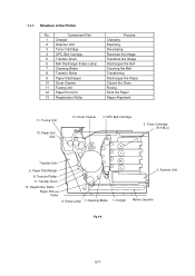
... 3. Erase Lamp 7. Fusing Unit 12. Registration Roller Paper Pick-up Roller 6. Component Part 1 Charger 2 Scanner Unit 3 Toner Cartridge 4 OPC Belt Cartridge 5 Transfer Drum 6 Belt Discharger Erase Lamp 7 Cleaning Blade 8 Transfer Roller 9 Paper Discharger 10 Drum Cleaner 11 Fusing Unit 12 Paper Exit Unit 13 Registration Roller Process Charging Exposing Developing Receives the Image...
... 3. Erase Lamp 7. Fusing Unit 12. Registration Roller Paper Pick-up Roller 6. Component Part 1 Charger 2 Scanner Unit 3 Toner Cartridge 4 OPC Belt Cartridge 5 Transfer Drum 6 Belt Discharger Erase Lamp 7 Cleaning Blade 8 Transfer Roller 9 Paper Discharger 10 Drum Cleaner 11 Fusing Unit 12 Paper Exit Unit 13 Registration Roller Process Charging Exposing Developing Receives the Image...

Service Manual
Page 59
... biased to the voltage -CBV(V) by the power supply DBV. Fuser Unit Cleaning Unit FCBV Cleaning Burush OPC Belt Paper Discharger Transfer Drum Toner Toner Cartridge K Develop Y ACHV Transfer Roller THV (+) THV ( - ) Paper Cleaning Blade Erase Lamp M C... Po ZDV Fig.4-9 No. Function 1 Charging 2 First Transfer 3 Developing Y,M Bias C,K 4 Second Transfer 5 Transfer Roller Cleaning 6 Paper Discharging 7 Drum Cleaning Power Supply (P/S) P/S Name Approx.Output Voltage CHV(-) 4.6KV HVRD6190 619V CBV(-) 200V 900V DBV(-A) 200V 400V DBV(-B) 200V 400V THV(+) 400V...
... biased to the voltage -CBV(V) by the power supply DBV. Fuser Unit Cleaning Unit FCBV Cleaning Burush OPC Belt Paper Discharger Transfer Drum Toner Toner Cartridge K Develop Y ACHV Transfer Roller THV (+) THV ( - ) Paper Cleaning Blade Erase Lamp M C... Po ZDV Fig.4-9 No. Function 1 Charging 2 First Transfer 3 Developing Y,M Bias C,K 4 Second Transfer 5 Transfer Roller Cleaning 6 Paper Discharging 7 Drum Cleaning Power Supply (P/S) P/S Name Approx.Output Voltage CHV(-) 4.6KV HVRD6190 619V CBV(-) 200V 900V DBV(-A) 200V 400V DBV(-B) 200V 400V THV(+) 400V...

Service Manual
Page 60
... as the result. VR DBV - iii) The potential of the exposure part of the OPC belt is reduced to -VR(V) as it is exposed to -CBV(V). VR Remain voltage on the OPC belt moves to the transfer drum surface in the process of potential between -VR(V) (the latent image) and -DBV(V), and a visible... toner image is initially biased to the laser beam in the transfer process because the GND potential of the transfer drum is greater than -VR(V) of OPC Belt Potential (See Fig.4-10.) i) The OPC belt is formed as the result. Process 1 2 34 5 Transfer...
... as the result. VR DBV - iii) The potential of the exposure part of the OPC belt is reduced to -VR(V) as it is exposed to -CBV(V). VR Remain voltage on the OPC belt moves to the transfer drum surface in the process of potential between -VR(V) (the latent image) and -DBV(V), and a visible... toner image is initially biased to the laser beam in the transfer process because the GND potential of the transfer drum is greater than -VR(V) of OPC Belt Potential (See Fig.4-10.) i) The OPC belt is formed as the result. Process 1 2 34 5 Transfer...

Service Manual
Page 65
Transfer Drum Aluminum Fig.4-17 Rubber IV-14 iii) Semiconductor rubber is used to Fig.4-8.) i) The drum is located as shown in Fig.4-8. iv) The transfer drum rotates by contacting and synchronizing with the OPC belt. ii) Material of the Transfer Drum (Refer to provide the drum surface as shown in Fig.417. 4 First Transfer (Drum) The first transfer process means that the toner image on the OPC belt is transferred onto the transfer drum. (1) Structure of the drum is aluminum.
Transfer Drum Aluminum Fig.4-17 Rubber IV-14 iii) Semiconductor rubber is used to Fig.4-8.) i) The drum is located as shown in Fig.4-8. iv) The transfer drum rotates by contacting and synchronizing with the OPC belt. ii) Material of the Transfer Drum (Refer to provide the drum surface as shown in Fig.417. 4 First Transfer (Drum) The first transfer process means that the toner image on the OPC belt is transferred onto the transfer drum. (1) Structure of the drum is aluminum.

Service Manual
Page 66
... complete toner image is transferred onto paper in sequence is moved from the OPC belt onto the transfer drum and the color toner images overlap on the OPC belt is nearly GND. OPC Belt Residual Charge Residual Toner Drum transferring Belt discharging (Erase Lamp) Belt cleaning (Blade) Fig.4-18 IV-15... The potential of the transfer drum is moved onto the transfer drum due to Fig.4-18.) i) The OPC belt has been through the development process and contacts and synchronizes with the transfer drum. iv) Toner that has been developed by each color in the...
... complete toner image is transferred onto paper in sequence is moved from the OPC belt onto the transfer drum and the color toner images overlap on the OPC belt is nearly GND. OPC Belt Residual Charge Residual Toner Drum transferring Belt discharging (Erase Lamp) Belt cleaning (Blade) Fig.4-18 IV-15... The potential of the transfer drum is moved onto the transfer drum due to Fig.4-18.) i) The OPC belt has been through the development process and contacts and synchronizes with the transfer drum. iv) Toner that has been developed by each color in the...

Service Manual
Page 67
5 Belt Discharging (Erase Lamp) The belt discharging process means that upon completion of the drum transfer process, an LED light is radiated onto the OPC belt prior to mechanically cleaning the belt to discharge the residual charge. (1) Structure of Discharging (Refer to Fig.4-19.) i) Though ... is located as shown in the drum transfer process, there is discharged by the radiation of the erase lamp light prior to the transfer drum in Fig.4-8. ii) The residual charge (-VR) on the OPC belt is still a residual charge on the OPC belt. Drum transferring Belt discharging (Erase Lamp) Belt...
5 Belt Discharging (Erase Lamp) The belt discharging process means that upon completion of the drum transfer process, an LED light is radiated onto the OPC belt prior to mechanically cleaning the belt to discharge the residual charge. (1) Structure of Discharging (Refer to Fig.4-19.) i) Though ... is located as shown in the drum transfer process, there is discharged by the radiation of the erase lamp light prior to the transfer drum in Fig.4-8. ii) The residual charge (-VR) on the OPC belt is still a residual charge on the OPC belt. Drum transferring Belt discharging (Erase Lamp) Belt...

Service Manual
Page 68
... residual toner is collected in the waste toner pack by the blade edge. Residual toner is residual toner on the OPC belt as it has not been completely transferred in the drum transfer process. 6 Belt Cleaning The belt cleaning process means that the residual toner adhering to the... OPC belt surface is mechanically scavenged. (1) Structure of Belt Cleaning The blade for the belt cleaning is located relative to the OPC belt cartridge as shown in Fig...
... residual toner is collected in the waste toner pack by the blade edge. Residual toner is residual toner on the OPC belt as it has not been completely transferred in the drum transfer process. 6 Belt Cleaning The belt cleaning process means that the residual toner adhering to the... OPC belt surface is mechanically scavenged. (1) Structure of Belt Cleaning The blade for the belt cleaning is located relative to the OPC belt cartridge as shown in Fig...

Service Manual
Page 83
...13 14 15 16 17 17-1 17-2 17-3 No. Photo sensor to detect if the toner is full of the transfer drum. Photo sensor to detect thet the paper exit tray is empty for Fusing Unit Paper Sensor Toner Key Sensor 2 Interlock Switch... detect rotation of exited papers. Photo sensor to detect that paper is wound around the transfer drum. PSU PT1 PT2 P.EN OIL OHP DPJ D.EN PBS TPD/TTR WTS DHP1, DHP2 F.CL...the fixing unit. Photo sensor to detect if the fusing unit oil is full of the OPC belt. This the safety interlock switch when opening the cover. Photo sensor to detect if ...
...13 14 15 16 17 17-1 17-2 17-3 No. Photo sensor to detect if the toner is full of the transfer drum. Photo sensor to detect thet the paper exit tray is empty for Fusing Unit Paper Sensor Toner Key Sensor 2 Interlock Switch... detect rotation of exited papers. Photo sensor to detect that paper is wound around the transfer drum. PSU PT1 PT2 P.EN OIL OHP DPJ D.EN PBS TPD/TTR WTS DHP1, DHP2 F.CL...the fixing unit. Photo sensor to detect if the fusing unit oil is full of the OPC belt. This the safety interlock switch when opening the cover. Photo sensor to detect if ...

Service Manual
Page 145
... more time at screen f) (b) to return to the selected code is the life for which you need the information. 2: Fuser Cleaner (FC) b) 7: OPC Belt Cartridge (BL) 8: Fusing Unit (FU) 9: Transfer Drum (TD) 10: Replacement Kit by e) pressing the - button. (f) (e) (d) (c) (b) Press the - Procedure Description of images or printouts corresponding d) to the service mode... SERVICE MODE NEXT CARE INFO 32 NEXT CARE 12345678910 12 16 NEXT FC ROLL 12000P NEXT BL UNIT 60000P NEXT FU UNIT 60000P NEXT TR DRUM 300000P NEXT 120K KIT 120000P V-20
... more time at screen f) (b) to return to the selected code is the life for which you need the information. 2: Fuser Cleaner (FC) b) 7: OPC Belt Cartridge (BL) 8: Fusing Unit (FU) 9: Transfer Drum (TD) 10: Replacement Kit by e) pressing the - button. (f) (e) (d) (c) (b) Press the - Procedure Description of images or printouts corresponding d) to the service mode... SERVICE MODE NEXT CARE INFO 32 NEXT CARE 12345678910 12 16 NEXT FC ROLL 12000P NEXT BL UNIT 60000P NEXT FU UNIT 60000P NEXT TR DRUM 300000P NEXT 120K KIT 120000P V-20

Service Manual
Page 149
... cleared. Make sure that you clear the relevant CLEAR CARE mode whenever replacing the applicable periodical replacement parts with new ones. YES/NO 2 Fuser Cleaner 7 OPC Belt Cartridge 8 Fusing Unit 9 Drum Cleaner Transfer Roller FC BC FU 120K OW d) 36 CLEAR CARE 12345678910 12 16 e) SERVICE MODE TEST PRINT 10 Transfer...
... cleared. Make sure that you clear the relevant CLEAR CARE mode whenever replacing the applicable periodical replacement parts with new ones. YES/NO 2 Fuser Cleaner 7 OPC Belt Cartridge 8 Fusing Unit 9 Drum Cleaner Transfer Roller FC BC FU 120K OW d) 36 CLEAR CARE 12345678910 12 16 e) SERVICE MODE TEST PRINT 10 Transfer...

Service Manual
Page 155
... Using the Back or Set button, select the desired code to be set and then press the Reprint button. 2: Fuser Cleaner (FC) (a) (b) b) 7: OPC Belt Cartridge (BC) (d) 8: Fusing Unit (FU) (e) 9: Transfer Drum (TD) (f) 10: 120K Replacement Kit (OW) (g) c) 13: Paper Pick-up Roller (PK) 14: Paper Pick-up Roller (PL) 16: Paper ...44 LIFE PERIOD 12345678910 12 16 PERIOD FC ROLL 012000 P SET PERIOD BC UNIT 60000 P SET PERIOD FU UNIT 60000 P SET PERIOD TR DRUM 300000 P SET PERIOD 120K UNIT 120000 P SET 44 LIFE PERIOD 12345678910 12 16 39 FACTORY MODE i) DP CHECK V-30 button one more ...
... Using the Back or Set button, select the desired code to be set and then press the Reprint button. 2: Fuser Cleaner (FC) (a) (b) b) 7: OPC Belt Cartridge (BC) (d) 8: Fusing Unit (FU) (e) 9: Transfer Drum (TD) (f) 10: 120K Replacement Kit (OW) (g) c) 13: Paper Pick-up Roller (PK) 14: Paper Pick-up Roller (PL) 16: Paper ...44 LIFE PERIOD 12345678910 12 16 PERIOD FC ROLL 012000 P SET PERIOD BC UNIT 60000 P SET PERIOD FU UNIT 60000 P SET PERIOD TR DRUM 300000 P SET PERIOD 120K UNIT 120000 P SET 44 LIFE PERIOD 12345678910 12 16 39 FACTORY MODE i) DP CHECK V-30 button one more ...
Service Manual
Page 165
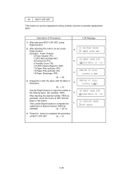
... or Set button. 49 NEXT LIFE SET This mode is to set , press a) Reprint button. (Example : Fuser Cleaner) 2:Fuser Cleaner (FC) 7:OPC Belt Cartridge (BC) 8:Fusing Unit (FU) b) 9:Transfer Drum (TD) 10:120K Volume Stack Kit (OW) 13:Paper Pick-up Roller (PK) 14:Paper Pick-up Roller (PL) 16:Paper Discharger...
... or Set button. 49 NEXT LIFE SET This mode is to set , press a) Reprint button. (Example : Fuser Cleaner) 2:Fuser Cleaner (FC) 7:OPC Belt Cartridge (BC) 8:Fusing Unit (FU) b) 9:Transfer Drum (TD) 10:120K Volume Stack Kit (OW) 13:Paper Pick-up Roller (PK) 14:Paper Pick-up Roller (PL) 16:Paper Discharger...

Service Manual
Page 167
... Adjustment of laser power THV TUNE UP Adjustment of transfer voltage DBV TUNE UP Adjustment of developer bias CBV TUNE UP Adjustment of OPC belt bias FBV TUNE UP Adjustment of Engine NVRAM Data As data in this chapter. 2) Select RAM TUNE UP mode. 3) ...out a test print to the media or operational conditions. 3.4.2 Setting of cleaning roller bias Purpose Optical density Transfer efficiency Optical density Optical density Drum cleaning efficiency V-42 Print quality can be required subject to confirm the print quality. However, fine adjustment may be improved by changing the ...
... Adjustment of laser power THV TUNE UP Adjustment of transfer voltage DBV TUNE UP Adjustment of developer bias CBV TUNE UP Adjustment of OPC belt bias FBV TUNE UP Adjustment of Engine NVRAM Data As data in this chapter. 2) Select RAM TUNE UP mode. 3) ...out a test print to the media or operational conditions. 3.4.2 Setting of cleaning roller bias Purpose Optical density Transfer efficiency Optical density Optical density Drum cleaning efficiency V-42 Print quality can be required subject to confirm the print quality. However, fine adjustment may be improved by changing the ...


