Users Manual - English
Page 2
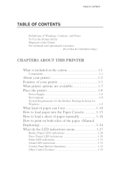
... technical and operational assistance (For USA & CANADA Only) CHAPTER1 ABOUT THIS PRINTER What is included in the carton 1-1 Components 1-1 About your printer 1-2 Features of your printer 1-3 What printer options are available 1-7 Place the printer 1-8 Power Supply 1-8 Environment 1-8 System Requirements for the Brother Printing Solution for Windows 1-9 What kind of paper can I use 1-10 How to load paper into...
... technical and operational assistance (For USA & CANADA Only) CHAPTER1 ABOUT THIS PRINTER What is included in the carton 1-1 Components 1-1 About your printer 1-2 Features of your printer 1-3 What printer options are available 1-7 Place the printer 1-8 Power Supply 1-8 Environment 1-8 System Requirements for the Brother Printing Solution for Windows 1-9 What kind of paper can I use 1-10 How to load paper into...

Users Manual - English
Page 16
..., shredder and so on a flat, horizontal surface. • Keep the printer clean. Place the printer Please take note of the following ranges of temperature and humidity. Power Supply • Use the printer within the following before using the printer. AC power: ±10% of the rated power voltage in your country Frequency: 50 Hz (220 V- 240 V) or 50...
..., shredder and so on a flat, horizontal surface. • Keep the printer clean. Place the printer Please take note of the following ranges of temperature and humidity. Power Supply • Use the printer within the following before using the printer. AC power: ±10% of the rated power voltage in your country Frequency: 50 Hz (220 V- 240 V) or 50...
Service Manual
Page 4
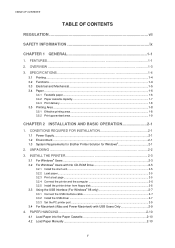
...area ...1-9 CHAPTER 2 INSTALLATION AND BASIC OPERATION 2-1 1. INSTALL THE PRINTER 2-3 3.1 For Windows® Users ...2-3 3.2 For Windows® Users with No ...printer port ...2-9 3.4 For Macintosh (iMac and Power Macintosh) with USB Users Only 2-9 4. TABLE OF CONTENTS TABLE OF CONTENTS REGULATION vii SAFETY INFORMATION ix CHAPTER 1 GENERAL 1-1 1. PAPER HANDLING 2-10 4.1 Load Paper into the Paper Cassette 2-10 4.2 Load Paper Manually ...2-10 ii CONDITIONS REQUIRED FOR INSTALLATION 2-1 1.1 Power Supply...2-1 1.2 Environment...2-1 1.3 System Requirements for Brother Printer...
...area ...1-9 CHAPTER 2 INSTALLATION AND BASIC OPERATION 2-1 1. INSTALL THE PRINTER 2-3 3.1 For Windows® Users ...2-3 3.2 For Windows® Users with No ...printer port ...2-9 3.4 For Macintosh (iMac and Power Macintosh) with USB Users Only 2-9 4. TABLE OF CONTENTS TABLE OF CONTENTS REGULATION vii SAFETY INFORMATION ix CHAPTER 1 GENERAL 1-1 1. PAPER HANDLING 2-10 4.1 Load Paper into the Paper Cassette 2-10 4.2 Load Paper Manually ...2-10 ii CONDITIONS REQUIRED FOR INSTALLATION 2-1 1.1 Power Supply...2-1 1.2 Environment...2-1 1.3 System Requirements for Brother Printer...

Service Manual
Page 5
...Printing (Manual Duplexing 2-11 4.3.1 To print on both sides of Printing Mechanism 3-17 2.2 Paper Transfer ...3-19 2.2.1 Paper supply ...3-19 2.2.2 Paper registration...3-19 2.2.3 Paper eject...3-20 2.3 Sensors...3-20 2.3.1 Cover sensors A and B ...3-20 2.3.2 ...Optional serial I/O ...3-12 1.3.6 EEPROM...3-12 1.3.7 Reset circuit ...3-13 1.3.8 Engine I/O ...3-14 1.4 Engine PCB ...3-14 1.5 Power Supply...3-15 1.5.1 Low-voltage Power Supply 3-15 1.5.2 High-voltage Power Supply 3-16 2. MECHANICS ...3-17 2.1 Overview of the paper from the paper cassette 2-11 4.3.2 To print on both sides ...
...Printing (Manual Duplexing 2-11 4.3.1 To print on both sides of Printing Mechanism 3-17 2.2 Paper Transfer ...3-19 2.2.1 Paper supply ...3-19 2.2.2 Paper registration...3-19 2.2.3 Paper eject...3-20 2.3 Sensors...3-20 2.3.1 Cover sensors A and B ...3-20 2.3.2 ...Optional serial I/O ...3-12 1.3.6 EEPROM...3-12 1.3.7 Reset circuit ...3-13 1.3.8 Engine I/O ...3-14 1.4 Engine PCB ...3-14 1.5 Power Supply...3-15 1.5.1 Low-voltage Power Supply 3-15 1.5.2 High-voltage Power Supply 3-16 2. MECHANICS ...3-17 2.1 Overview of the paper from the paper cassette 2-11 4.3.2 To print on both sides ...

Service Manual
Page 6
... Fixing stage...3-24 CHAPTER 4 DISASSEMBLY AND RE-ASSEMBLY 4-1 1. MTBF / MTTR ...5-7 iv DISASSEMBLY FLOW 4-2 3. PERIODICAL CLEANING 5-5 3.1 Cleaning the Printer Exterior 5-5 3.2 Cleaning the Drum Unit...5-5 3.3 Cleaning the Scanner Window 5-6 3.4 Cleaning the Electrical Terminals 5-6 4. CONSUMABLE PARTS 5-1 1.1 Drum Unit...Laser Unit...4-13 3.8 Drive Unit ...4-14 3.9 Fixing Unit ...4-17 3.10 Base Plate...4-25 3.11 Main PCB ASSY ...4-26 3.12 Lower Tray Relay PCB ASSY (HL-1250 only 4-26 3.13 Low-voltage Power Supply PCB ASSY 4-27 3.14 Engine PCB ASSY / High-voltage Power Supply...
... Fixing stage...3-24 CHAPTER 4 DISASSEMBLY AND RE-ASSEMBLY 4-1 1. MTBF / MTTR ...5-7 iv DISASSEMBLY FLOW 4-2 3. PERIODICAL CLEANING 5-5 3.1 Cleaning the Printer Exterior 5-5 3.2 Cleaning the Drum Unit...5-5 3.3 Cleaning the Scanner Window 5-6 3.4 Cleaning the Electrical Terminals 5-6 4. CONSUMABLE PARTS 5-1 1.1 Drum Unit...Laser Unit...4-13 3.8 Drive Unit ...4-14 3.9 Fixing Unit ...4-17 3.10 Base Plate...4-25 3.11 Main PCB ASSY ...4-26 3.12 Lower Tray Relay PCB ASSY (HL-1250 only 4-26 3.13 Low-voltage Power Supply PCB ASSY 4-27 3.14 Engine PCB ASSY / High-voltage Power Supply...

Service Manual
Page 10
... countries where required. The label shown below is adjusted in the Laser Unit. CLASS 1 LASER PRODUCT APPAREIL LASER DE CLASSE 1 LASER KLASSE 1 PRODUKT This printer has a laser diode which emits invisible laser radiation in accordance with the AC power supply and laser unit. Since the variable resistor in the laser unit is attached in IEC 825 specifications. For Finland and Sweden...
... countries where required. The label shown below is adjusted in the Laser Unit. CLASS 1 LASER PRODUCT APPAREIL LASER DE CLASSE 1 LASER KLASSE 1 PRODUKT This printer has a laser diode which emits invisible laser radiation in accordance with the AC power supply and laser unit. Since the variable resistor in the laser unit is attached in IEC 825 specifications. For Finland and Sweden...

Service Manual
Page 23
... a heavy curtain to setup and operate the printer using Brother Printing Solution for the printer driver and all fonts. Do not place the printer near devices that you must stay within ±10% of the printer is maintained between the ventilation hole and the wall. CONDITIONS REQUIRED FOR INSTALLATION 1.1 Power Supply The source voltage must use the...
... a heavy curtain to setup and operate the printer using Brother Printing Solution for the printer driver and all fonts. Do not place the printer near devices that you must stay within ±10% of the printer is maintained between the ventilation hole and the wall. CONDITIONS REQUIRED FOR INSTALLATION 1.1 Power Supply The source voltage must use the...

Service Manual
Page 39
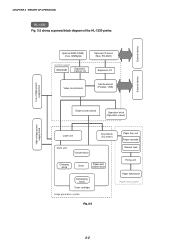
... block (Parallel / USB) External device Low-voltage power supply block High-voltage power supply block Engine control block Operation block (Control panel) Laser unit Drive block (DC motor) Drum unit Transfer ...block Charging block Drum Paper dust cleaner block Developing block Toner cartridge Image generation system Paper tray unit Paper cassette Manual feed Fixing unit Paper eject block Paper feed system Fig. 3-1 3-1 ELECTRONICS 1.1 General Block Diagram HL-1240 Fig. 3-1 shows a general block diagram of the HL-1240 printer...
... block (Parallel / USB) External device Low-voltage power supply block High-voltage power supply block Engine control block Operation block (Control panel) Laser unit Drive block (DC motor) Drum unit Transfer ...block Charging block Drum Paper dust cleaner block Developing block Toner cartridge Image generation system Paper tray unit Paper cassette Manual feed Fixing unit Paper eject block Paper feed system Fig. 3-1 3-1 ELECTRONICS 1.1 General Block Diagram HL-1240 Fig. 3-1 shows a general block diagram of the HL-1240 printer...
Service Manual
Page 40
... block diagram of the HL-1250 printer. RS-232C) Expansion I /F board (Mac. External device Optional RAM (SIMM) (max. 32Mbytes) Control system RAM 4MB Expansion memory I/O Optional I /O Video control block Interface block (Parallel / USB) External device Low-voltage power supply block High-voltage power supply block Engine control block Operation block (Operation panel) Laser unit Drive block (DC...
... block diagram of the HL-1250 printer. RS-232C) Expansion I /F board (Mac. External device Optional RAM (SIMM) (max. 32Mbytes) Control system RAM 4MB Expansion memory I/O Optional I /O Video control block Interface block (Parallel / USB) External device Low-voltage power supply block High-voltage power supply block Engine control block Operation block (Operation panel) Laser unit Drive block (DC...

Service Manual
Page 52
... Fan motor Front registration sensor Thermistor Rear registration sensor Polygon motor Upper paper cassette sensor (HL-1250 only) Solenoid Lower paper cassette registration sensor (HL-1250 only) High-voltage power supply 3-14 CHAPTER 3 THEORY OF OPERATION 1.3.8 Engine I/O HL-1240 Fig. 3-17 shows the engine interface circuit. Fig. 3-17 HL-1250 Fig. 3-18 shows the engine interface circuit.
... Fan motor Front registration sensor Thermistor Rear registration sensor Polygon motor Upper paper cassette sensor (HL-1250 only) Solenoid Lower paper cassette registration sensor (HL-1250 only) High-voltage power supply 3-14 CHAPTER 3 THEORY OF OPERATION 1.3.8 Engine I/O HL-1240 Fig. 3-17 shows the engine interface circuit. Fig. 3-17 HL-1250 Fig. 3-18 shows the engine interface circuit.

Service Manual
Page 53
... Rectifier Feedback Oscillator 24V Regulation Circuit 5V Regulation Circuit Fig. 3-19 3-15 (Engin Circuit) 24V 5V The regulated output and the production code of each power supply are converted from the AC line. CHAPTER 3 THEORY OF OPERATION 1.5 Power Supply 1.5.1 Low-voltage power supply The power supply uses a switching regulation system to generate the regulated DC...
... Rectifier Feedback Oscillator 24V Regulation Circuit 5V Regulation Circuit Fig. 3-19 3-15 (Engin Circuit) 24V 5V The regulated output and the production code of each power supply are converted from the AC line. CHAPTER 3 THEORY OF OPERATION 1.5 Power Supply 1.5.1 Low-voltage power supply The power supply uses a switching regulation system to generate the regulated DC...

Service Manual
Page 54
R1 24VI GND Current Regulator B1 Voltage Regulator VR22 Current Regulator B102 Q81 Voltage Regulator B101 Q101 Voltage Regulator Z51 VR51 Supply Roller Transfer Roller Development Roller Photosensitive Drum Corona Unit Fig. 3-20 3-16 CHAPTER 3 THEORY OF OPERATION 1.5.2 High-voltage power supply The high-voltage power supply generates and outputs the voltages and currents for the charging, development and transfer functions.
R1 24VI GND Current Regulator B1 Voltage Regulator VR22 Current Regulator B102 Q81 Voltage Regulator B101 Q101 Voltage Regulator Z51 VR51 Supply Roller Transfer Roller Development Roller Photosensitive Drum Corona Unit Fig. 3-20 3-16 CHAPTER 3 THEORY OF OPERATION 1.5.2 High-voltage power supply The high-voltage power supply generates and outputs the voltages and currents for the charging, development and transfer functions.

Service Manual
Page 56
CHAPTER 3 THEORY OF OPERATION Main PCB Low-Voltage Power Supply PCB Fixing Unit Halogen Heater Lamp Laser Unit Laser Polygon Motor Engine PCB Front Registration Sensor Rear Registration Sensor Upper Paper Cassette Sensor (HL-1250) Lower Paper Cassette Registration Sensor (HL-1250) HighVoltage Power Supply PCB Cover Sensor (B) Drum Unit Primary Charger (Corona Wire) Primary Charger (Grid) Development Roller...
CHAPTER 3 THEORY OF OPERATION Main PCB Low-Voltage Power Supply PCB Fixing Unit Halogen Heater Lamp Laser Unit Laser Polygon Motor Engine PCB Front Registration Sensor Rear Registration Sensor Upper Paper Cassette Sensor (HL-1250) Lower Paper Cassette Registration Sensor (HL-1250) HighVoltage Power Supply PCB Cover Sensor (B) Drum Unit Primary Charger (Corona Wire) Primary Charger (Grid) Development Roller...

Service Manual
Page 60
...the photosensitive drum is generated by ionization of ozone expelled from the printer is distributed evenly on the drum surface. Drum Laser beam Laser detector Paper Laser beam f lens Polygon mirror Laser diode Lens Motor Fig. 3-29 3-22 The level of the... 3 THEORY OF OPERATION 2.6 Print Process 2.6.1 Charging The drum is charged to approximately 870V by an ion charge which has a DC bias from the high-voltage power supply applied to it. Voltage Regulator +++-+--+--+- 870V - + -- - ++ + - + + + + + + + ++ + + Aluminum drum sleeve Photosensitive Organic Photoconductor ...
...the photosensitive drum is generated by ionization of ozone expelled from the printer is distributed evenly on the drum surface. Drum Laser beam Laser detector Paper Laser beam f lens Polygon mirror Laser diode Lens Motor Fig. 3-29 3-22 The level of the... 3 THEORY OF OPERATION 2.6 Print Process 2.6.1 Charging The drum is charged to approximately 870V by an ion charge which has a DC bias from the high-voltage power supply applied to it. Voltage Regulator +++-+--+--+- 870V - + -- - ++ + - + + + + + + + ++ + + Aluminum drum sleeve Photosensitive Organic Photoconductor ...

Service Manual
Page 61
... charging 2 Laser beam exposure and developing (a) Unexposed area ( Non image area ) (b) Exposed area ( Image area ) 3 Transfer the image to paper Drum Sleeve 0 Time Fig. 3-30 2.6.3 Developing Developing causes the toner to be printed. The toner is DC-biased from the high-voltage power supply, creates the... electrostatic potential to attract toner particles from the supply roller to the development roller. Blade Development roller Corona wire Photosensitive drum Transfer roller Supply roller Fig. 3-31 3-23 The ...
... charging 2 Laser beam exposure and developing (a) Unexposed area ( Non image area ) (b) Exposed area ( Image area ) 3 Transfer the image to paper Drum Sleeve 0 Time Fig. 3-30 2.6.3 Developing Developing causes the toner to be printed. The toner is DC-biased from the high-voltage power supply, creates the... electrostatic potential to attract toner particles from the supply roller to the development roller. Blade Development roller Corona wire Photosensitive drum Transfer roller Supply roller Fig. 3-31 3-23 The ...

Service Manual
Page 88
... to the rear of the ground wire may cause increased printer noise. CAUTION: • When re-assembling the base plate, be sure that the ground wire connected to the paper feed roller ASSY is not necessary to remove the low-voltage power supply unit. CAUTION: Do not remove the ground wire connected to... Taptite, bind M3x8 Taptite, bind M3x8 Main frame Ground wire connection Taptite, bind M3x8 Base plate Taptite, bind M3x8 Fig. 4-45 ! Unnecessary disconnection of the printer to the figure below; Ground wire Plastic chute Fig. 4-46 4-25 (slit) Main frame
... to the rear of the ground wire may cause increased printer noise. CAUTION: • When re-assembling the base plate, be sure that the ground wire connected to the paper feed roller ASSY is not necessary to remove the low-voltage power supply unit. CAUTION: Do not remove the ground wire connected to... Taptite, bind M3x8 Taptite, bind M3x8 Main frame Ground wire connection Taptite, bind M3x8 Base plate Taptite, bind M3x8 Fig. 4-45 ! Unnecessary disconnection of the printer to the figure below; Ground wire Plastic chute Fig. 4-46 4-25 (slit) Main frame

Service Manual
Page 90
...M3x6 Lower tray relay PCB ASSY Lower tray relay PCB ASSY Fig. 4-47 4-26 Insulation sheet Main PCB LD connector Engine PCB connector Low-voltage power supply connector ➁ ➀ Screw M3x8 I /F plate to release the main PCB. (2) Lift the insulation sheet and remove the main PCB ASSY.... (3) Disconnect the three connectors for the low-voltage power supply, engine PCB and LD. CHAPTER 4 DISASSEMBLY AND RE-ASSEMBLY 3.11 Main PCB ASSY (1) Remove the two M3x8 screws from the I /F plate Fig....
...M3x6 Lower tray relay PCB ASSY Lower tray relay PCB ASSY Fig. 4-47 4-26 Insulation sheet Main PCB LD connector Engine PCB connector Low-voltage power supply connector ➁ ➀ Screw M3x8 I /F plate to release the main PCB. (2) Lift the insulation sheet and remove the main PCB ASSY.... (3) Disconnect the three connectors for the low-voltage power supply, engine PCB and LD. CHAPTER 4 DISASSEMBLY AND RE-ASSEMBLY 3.11 Main PCB ASSY (1) Remove the two M3x8 screws from the I /F plate Fig....

Service Manual
Page 91
...first, then secure it and remove the AC inlet ASSY and the low- voltage power supply PCB together. Taptite, bind M3x8 Insulation sheet Low-voltage power supply PCB ASSY AC inlet holder Ground wire Screw M3.5x6 Base plate Low-voltage power supply PCB ASSY Step (2) Halogen heater lamp connector Engine PCB connector Fig. 4-48 (4)...right to release it to the frame with the screw. (Refer to the figure above.) 4-27 CHAPTER 4 DISASSEMBLY AND RE-ASSEMBLY 3.13 Low-Voltage Power Supply PCB ASSY (1) Remove the M3x8 Taptite screw to remove the insulation sheet. (2) Slightly lift up the low-voltage...
...first, then secure it and remove the AC inlet ASSY and the low- voltage power supply PCB together. Taptite, bind M3x8 Insulation sheet Low-voltage power supply PCB ASSY AC inlet holder Ground wire Screw M3.5x6 Base plate Low-voltage power supply PCB ASSY Step (2) Halogen heater lamp connector Engine PCB connector Fig. 4-48 (4)...right to release it to the frame with the screw. (Refer to the figure above.) 4-27 CHAPTER 4 DISASSEMBLY AND RE-ASSEMBLY 3.13 Low-Voltage Power Supply PCB ASSY (1) Remove the M3x8 Taptite screw to remove the insulation sheet. (2) Slightly lift up the low-voltage...

Service Manual
Page 92
...insulation sheet. (2) Remove the three M4x12 Taptite screws securing the engine PCB and the high-voltage power supply PCB. (3) Lift the engine PCB and high-voltage power supply PCB together and disconnect the connector which connects two PCBs together to lose the T/R electrode helical... (3) Screw, bind M4x12 Engine PCB ASSY Screw, bind M4x12 T/R electrode helical spring Step (4) T/R plate High-voltage power supply PCB ASSY Fig. 4-50 ! CAUTION: Be sure not to remove the high-voltage power supply PCB ASSY. (4) If necessary, remove the T/R electrode helical spring from the T/R plate.
...insulation sheet. (2) Remove the three M4x12 Taptite screws securing the engine PCB and the high-voltage power supply PCB. (3) Lift the engine PCB and high-voltage power supply PCB together and disconnect the connector which connects two PCBs together to lose the T/R electrode helical... (3) Screw, bind M4x12 Engine PCB ASSY Screw, bind M4x12 T/R electrode helical spring Step (4) T/R plate High-voltage power supply PCB ASSY Fig. 4-50 ! CAUTION: Be sure not to remove the high-voltage power supply PCB ASSY. (4) If necessary, remove the T/R electrode helical spring from the T/R plate.

Service Manual
Page 93
CHAPTER 4 DISASSEMBLY AND RE-ASSEMBLY (5) Disconnect the 11 (eleven) connectors for HL-1240 or 12 (twelve) connectors for HVPS) Main PCB connector Low-voltage power supply connector Engine PCB ASSY Thermistor connector Fan motor connector Toner sensor (light emission) connector Polygon motor connector Solenoid .... Be careful the main motor harness is aligned with the positioning boss first. Toner sensor (light reception) connector Low-voltage power supply connector (for HL-1250 from the engine PCB to do may damage the PCBs. When re-assembling the engine PCB, ensure it is not...
CHAPTER 4 DISASSEMBLY AND RE-ASSEMBLY (5) Disconnect the 11 (eleven) connectors for HL-1240 or 12 (twelve) connectors for HVPS) Main PCB connector Low-voltage power supply connector Engine PCB ASSY Thermistor connector Fan motor connector Toner sensor (light emission) connector Polygon motor connector Solenoid .... Be careful the main motor harness is aligned with the positioning boss first. Toner sensor (light reception) connector Low-voltage power supply connector (for HL-1250 from the engine PCB to do may damage the PCBs. When re-assembling the engine PCB, ensure it is not...


