
Users Manual - English
Page 9
... of purchase for labour and parts, Brother International Corporation (Canada) Ltd. ("Brother"), or its Authorized Service Centres, Distributors, Dealers, Agents or employees, shall create another warranty or modify this warranty. For inkjet units: (When shipping your nearest Authorized Service Centre call 1-877-BROTHER. Improper packaging may also have other than a Brother Authorized Service Representative, or if...
... of purchase for labour and parts, Brother International Corporation (Canada) Ltd. ("Brother"), or its Authorized Service Centres, Distributors, Dealers, Agents or employees, shall create another warranty or modify this warranty. For inkjet units: (When shipping your nearest Authorized Service Centre call 1-877-BROTHER. Improper packaging may also have other than a Brother Authorized Service Representative, or if...

Users Manual - English
Page 96
... a toner cartridge on the USB Flash memory drive or the file you are trying to save . C 1-877-BROTHER (1-877-276-8437) (in USA) 1-877-BROTHER (in Canada) Replace Parts Laser Unit It is time to replace the paper feeding kit for Tray 2. several minutes, then reconnect it. Call...Cause Action Replace Parts The drum unit is time to replace the fuser unit. Call Brother Customer Service to replace the laser unit. 1-877-BROTHER (1-877-276-8437) (in USA) 1-877-BROTHER (in Canada) Replace Parts PF Kit 1 It is time to replace the laser unit. Replace Toner The toner cartridge ...
... a toner cartridge on the USB Flash memory drive or the file you are trying to save . C 1-877-BROTHER (1-877-276-8437) (in USA) 1-877-BROTHER (in Canada) Replace Parts Laser Unit It is time to replace the paper feeding kit for Tray 2. several minutes, then reconnect it. Call...Cause Action Replace Parts The drum unit is time to replace the fuser unit. Call Brother Customer Service to replace the laser unit. 1-877-BROTHER (1-877-276-8437) (in USA) 1-877-BROTHER (in Canada) Replace Parts PF Kit 1 It is time to replace the laser unit. Replace Toner The toner cartridge ...
Users Manual - English
Page 119
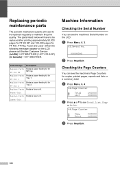
... see the machine's Serial Number on the LCD please call Brother Customer Service (in USA) 1-877-BROTHER (1-877-276-8437) (in Canada) 1-877- Fuser Unit Replace Parts Replace laser unit. a Press Menu, 6, 3. 63.Serial No. Laser Unit Machine Information C Checking the Serial Number C You can see... the machine's Page Counters for Tray 2. BROTHER. XXXXXXXXX b Press Stop/Exit. Replacing periodic ...
... see the machine's Serial Number on the LCD please call Brother Customer Service (in USA) 1-877-BROTHER (1-877-276-8437) (in Canada) 1-877- Fuser Unit Replace Parts Replace laser unit. a Press Menu, 6, 3. 63.Serial No. Laser Unit Machine Information C Checking the Serial Number C You can see... the machine's Page Counters for Tray 2. BROTHER. XXXXXXXXX b Press Stop/Exit. Replacing periodic ...
Parts List
Page 3
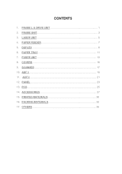
DUPLEX 9 6. FUSER UNIT 13 8. ADF 2 21 12. PANEL 23 13. PACKING MATERIALS 32 17. PAPER FEEDER 7 5. LASER UNIT 5 4. ADF 1 19 11. ACCESSORIES 27 15. PRINTED MATERIALS 30 16. OTHERS 35 CONTENTS 1. FRAME UNIT 3 3. COVERS 15 9. FRAME L & DRIVE UNIT 1 2. PCB ...25 14. PAPER TRAY 11 7. SCANNER 17 10.
DUPLEX 9 6. FUSER UNIT 13 8. ADF 2 21 12. PANEL 23 13. PACKING MATERIALS 32 17. PAPER FEEDER 7 5. LASER UNIT 5 4. ADF 1 19 11. ACCESSORIES 27 15. PRINTED MATERIALS 30 16. OTHERS 35 CONTENTS 1. FRAME UNIT 3 3. COVERS 15 9. FRAME L & DRIVE UNIT 1 2. PCB ...25 14. PAPER TRAY 11 7. SCANNER 17 10.

Service Manual
Page 5
...1284 compliant. (2) A USB cable. CLASS 1 LASER PRODUCT APPAREIL À LASER DE CLASSE 1 LASER KLASSE 1 PRODUKT This machine has a Class 3B laser diode which produces invisible laser radiation in the laser unit. For Finland and Sweden LUOKAN 1 LASERLAITE KLASS 1 LASER APPARAT Varoitus! Varning Om apparaten används...Publication 22)/Class B. Before you use this User's Guide may result in hazardous radiation exposure. You should not open the laser unit under any circumstances. Laitteen käyttäminen muulla kuin tässä käyttöohjeessa mainitulla tavalla ...
...1284 compliant. (2) A USB cable. CLASS 1 LASER PRODUCT APPAREIL À LASER DE CLASSE 1 LASER KLASSE 1 PRODUKT This machine has a Class 3B laser diode which produces invisible laser radiation in the laser unit. For Finland and Sweden LUOKAN 1 LASERLAITE KLASS 1 LASER APPARAT Varoitus! Varning Om apparaten används...Publication 22)/Class B. Before you use this User's Guide may result in hazardous radiation exposure. You should not open the laser unit under any circumstances. Laitteen käyttäminen muulla kuin tässä käyttöohjeessa mainitulla tavalla ...

Service Manual
Page 9
... accessories such as watches and rings before working on the laser unit. Since the beam is invisible, the following caution label is operated with the laser unit, replace the laser unit itself. To prevent direct exposure to the laser beam, do not try to take off any trouble with... the cover open the enclosure of the laser beam. A reflected beam, though invisible, can permanently ...
... accessories such as watches and rings before working on the laser unit. Since the beam is invisible, the following caution label is operated with the laser unit, replace the laser unit itself. To prevent direct exposure to the laser beam, do not try to take off any trouble with... the cover open the enclosure of the laser beam. A reflected beam, though invisible, can permanently ...
Service Manual
Page 14
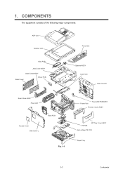
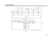
COMPONENTS The equipment consists of the following major components: ADF Unit Scanner Unit Panel Unit NCU PCB Joint Cover ASSY Outer Chute ASSY Back Cover Driver PCB Speaker ASSY Laser Unit Side Cover R Rear Chute ASSY Fuser Unit Access Cover Side Cover L Main PCB Fig. 1-1 Frame Unit Toner LED PCB ASSY Process Cover ASSY PS PCB MP Tray Cover ASSY High-voltage PS PCB Paper Tray 1-1 Confidential 1.
COMPONENTS The equipment consists of the following major components: ADF Unit Scanner Unit Panel Unit NCU PCB Joint Cover ASSY Outer Chute ASSY Back Cover Driver PCB Speaker ASSY Laser Unit Side Cover R Rear Chute ASSY Fuser Unit Access Cover Side Cover L Main PCB Fig. 1-1 Frame Unit Toner LED PCB ASSY Process Cover ASSY PS PCB MP Tray Cover ASSY High-voltage PS PCB Paper Tray 1-1 Confidential 1.

Service Manual
Page 21
Machine life: 200,000 pages MTBF (Meantime between failure): Up to 4000 hours MTTR (Meantime to repair): Average 0.5 hours Monthly volume: 30,000 pages Periodical replacement parts: Parts Approximate Life (pages) Fuser unit 100,000 Laser unit 100,000 PF kit China MP: 25,000 Tray 1/2: 100,000 India MP: 12,000 Tray 1/2: 80,000 Others MP: 50,000 Tray 1/2: 100,000 * As for periodical replacement parts, refer to maintain the product. 2.5 Service Information These are key service information to CHAPTER 4 in the Service Manual. 1-8 Confidential
Machine life: 200,000 pages MTBF (Meantime between failure): Up to 4000 hours MTTR (Meantime to repair): Average 0.5 hours Monthly volume: 30,000 pages Periodical replacement parts: Parts Approximate Life (pages) Fuser unit 100,000 Laser unit 100,000 PF kit China MP: 25,000 Tray 1/2: 100,000 India MP: 12,000 Tray 1/2: 80,000 Others MP: 50,000 Tray 1/2: 100,000 * As for periodical replacement parts, refer to maintain the product. 2.5 Service Information These are key service information to CHAPTER 4 in the Service Manual. 1-8 Confidential
Service Manual
Page 39
... panel Centronics parallel interface USB interface WLAN PCB LAN interface USB interface Line Control Section Fax data Printer data NCU* Speaker ADF unit Scanner unit Laser printing unit Paper Low- ADF motor - Laser unit (including the polygon motor) - Transfer roller - CCD motor Charging, exposing, developing, transferring, and feeding mechanism high-voltage power supplies AC heat-fixing...
... panel Centronics parallel interface USB interface WLAN PCB LAN interface USB interface Line Control Section Fax data Printer data NCU* Speaker ADF unit Scanner unit Laser printing unit Paper Low- ADF motor - Laser unit (including the polygon motor) - Transfer roller - CCD motor Charging, exposing, developing, transferring, and feeding mechanism high-voltage power supplies AC heat-fixing...
Service Manual
Page 41
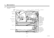
... Drawing - Printer part Paper stack lever Transfer roller Eject roller 2 Back cover Heat roller Eject roller 1 Paper eject actuator Pressure roller Duplex unit Paper tray Paper tray (LT unit) Laser unit Corona wire Exposure drum Develop roller Fig. 2-3 2-3 MP tray Regist roller Separation rollerMMPP Separation pad MP Paper feed roller MP Regist actuator rear...
... Drawing - Printer part Paper stack lever Transfer roller Eject roller 2 Back cover Heat roller Eject roller 1 Paper eject actuator Pressure roller Duplex unit Paper tray Paper tray (LT unit) Laser unit Corona wire Exposure drum Develop roller Fig. 2-3 2-3 MP tray Regist roller Separation rollerMMPP Separation pad MP Paper feed roller MP Regist actuator rear...
Service Manual
Page 65
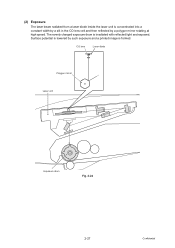
Surface potential is lowered by a polygon mirror rotating at high speed. (2) Exposure The laser beam radiated from a laser diode inside the laser unit is concentrated into a constant width by a slit in the CO lens cell and then reflected by such exposure and a printed image is formed. CO lens Laser diode Polygon mirror Laser unit Exposure drum Fig. 2-24 2-27 Confidential The evenly charged exposure drum is irradiated with reflected light and exposed.
Surface potential is lowered by a polygon mirror rotating at high speed. (2) Exposure The laser beam radiated from a laser diode inside the laser unit is concentrated into a constant width by a slit in the CO lens cell and then reflected by such exposure and a printed image is formed. CO lens Laser diode Polygon mirror Laser unit Exposure drum Fig. 2-24 2-27 Confidential The evenly charged exposure drum is irradiated with reflected light and exposed.
Service Manual
Page 74
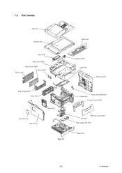
1.2 Part names ADF Unit Scanner Unit NCU PCB Joint Cover ASSY Outer Chute ASSY Back Cover Driver PCB Panel Unit Speaker ASSY Laser Unit Side Cover R Rear Chute ASSY Fuser Unit Access Cover Side Cover L Main PCB Fig. 3-1 Frame Unit Toner LED PCB ASSY Process Cover ASSY PS PCB MP Tray Cover ASSY High-voltage PS PCB Paper Tray 3-2 Confidential
1.2 Part names ADF Unit Scanner Unit NCU PCB Joint Cover ASSY Outer Chute ASSY Back Cover Driver PCB Panel Unit Speaker ASSY Laser Unit Side Cover R Rear Chute ASSY Fuser Unit Access Cover Side Cover L Main PCB Fig. 3-1 Frame Unit Toner LED PCB ASSY Process Cover ASSY PS PCB MP Tray Cover ASSY High-voltage PS PCB Paper Tray 3-2 Confidential
Service Manual
Page 77
... that is indicated on the LCD Error Message Access Error Cartridge Error Replace Parts Drum Replace Parts Fuser Unit Replace Parts Laser Unit Replace Parts PF Kit MP Replace Parts PF Kit 1 Replace Parts PF Kit 2 Comm.Error Connection Fail Type of a problem ...(if any), the facsimile equipment incorporates the self-diagnostic functions which display error messages for Tray 2. The drum unit counter was installed. 2) Press 1 to replace the laser unit. Replace the PF Kit 2. 3-15 Poor telephone line quality Send the fax again or connect the caused a communication machine...
... that is indicated on the LCD Error Message Access Error Cartridge Error Replace Parts Drum Replace Parts Fuser Unit Replace Parts Laser Unit Replace Parts PF Kit MP Replace Parts PF Kit 1 Replace Parts PF Kit 2 Comm.Error Connection Fail Type of a problem ...(if any), the facsimile equipment incorporates the self-diagnostic functions which display error messages for Tray 2. The drum unit counter was installed. 2) Press 1 to replace the laser unit. Replace the PF Kit 2. 3-15 Poor telephone line quality Send the fax again or connect the caused a communication machine...

Service Manual
Page 81
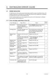
... to quickly find out the problem. 3.1 Error Indication Error codes Problem 1E Replacement time of the drum unit 1F Two or more optional trays are installed 24 Internal temperature sensor failure 35 EEPROM of main PCB failure 36 HVPS PCB during standby failure Main PCB RAM failure... 3-14 6F high temperature of the center or side thermistors 3-19 3-14 70 Fuser motor error 3-20 3-15 71 Laser unit polygon mirror failure 3-20 3-15 72 Laser beam emission failure 3-20 Sensor of the inside 3-15 75 temperature for detection detected higher than constant temperature 3-20 3-15...
... to quickly find out the problem. 3.1 Error Indication Error codes Problem 1E Replacement time of the drum unit 1F Two or more optional trays are installed 24 Internal temperature sensor failure 35 EEPROM of main PCB failure 36 HVPS PCB during standby failure Main PCB RAM failure... 3-14 6F high temperature of the center or side thermistors 3-19 3-14 70 Fuser motor error 3-20 3-15 71 Laser unit polygon mirror failure 3-20 3-15 72 Laser beam emission failure 3-20 Sensor of the inside 3-15 75 temperature for detection detected higher than constant temperature 3-20 3-15...

Service Manual
Page 87
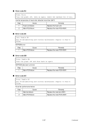
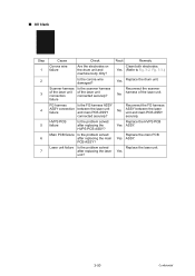
Step 1 Cause Remedy Replacement time of the fuser unit Replace the fuser unit. ■ Error code 55 Replace Parts Laser Unit Replacement time of the laser unit Step Cause Remedy 1 Replacement time of the paper feed kit T2 User Check • Replace the paper feed kit T2 with a new one. ■ Error ...
Step 1 Cause Remedy Replacement time of the fuser unit Replace the fuser unit. ■ Error code 55 Replace Parts Laser Unit Replacement time of the laser unit Step Cause Remedy 1 Replacement time of the paper feed kit T2 User Check • Replace the paper feed kit T2 with a new one. ■ Error ...

Service Manual
Page 92
Step 1 2 Cause Thermistor ASSY failure Main PCB failure Remedy Replace the laser scanner unit. Replace the main PCB ASSY. 3-20 Confidential Fuser motor error Step 1 2 Cause Motor failure Main PCB failure Remedy Replace the main motor. Replace the main ... constant temperature User Check • Lower the inside temperature. ■ Error code 70 Print Unable 70 Turn the power off and then back on again. Laser unit polygon mirror failure Error code 72 Print Unable 72 Turn the power off and then back on again. Replace the main PCB ASSY. ■ Error...
Step 1 2 Cause Thermistor ASSY failure Main PCB failure Remedy Replace the laser scanner unit. Replace the main PCB ASSY. 3-20 Confidential Fuser motor error Step 1 2 Cause Motor failure Main PCB failure Remedy Replace the main motor. Replace the main ... constant temperature User Check • Lower the inside temperature. ■ Error code 70 Print Unable 70 Turn the power off and then back on again. Laser unit polygon mirror failure Error code 72 Print Unable 72 Turn the power off and then back on again. Replace the main PCB ASSY. ■ Error...
Service Manual
Page 109
Central temperature of heat roller detected more than 280°C Step 1 2 Cause Fuser unit failure Main PCB failure Remedy Replace the fuser unit. Leave the machine for 15 min. Replace the main PCB ASSY. ■ Error code E6 Init Unable E6 See Troubleshooting and routine... back on again. Fuser fan performance failure Step 1 2 Cause Main fan failure Main PCB failure Remedy Replace the main fan ASSY. E2PROM data laser unit error Step 1 Cause Main PCB failure Remedy Replace the main PCB ASSY. ■ Error code EC Print Unable EC See Troubleshooting and routine maintenance...
Central temperature of heat roller detected more than 280°C Step 1 2 Cause Fuser unit failure Main PCB failure Remedy Replace the fuser unit. Leave the machine for 15 min. Replace the main PCB ASSY. ■ Error code E6 Init Unable E6 See Troubleshooting and routine... back on again. Fuser fan performance failure Step 1 2 Cause Main fan failure Main PCB failure Remedy Replace the main fan ASSY. E2PROM data laser unit error Step 1 Cause Main PCB failure Remedy Replace the main PCB ASSY. ■ Error code EC Print Unable EC See Troubleshooting and routine maintenance...
Service Manual
Page 118
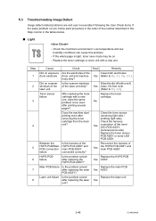
.... (luminescence side) Replace the toner sensor PCB ASSY or toner LED PCB ASSY. Laser unit failure Is the problem solved after removing the toner cartridge from the drum unit? drum electrode drum unit and machine Yes (Refer to Fig. 3-6.) Toner sensor failure After replacing the toner ...cartridge with a new one . No Does the machine start printing even after replacing the laser unit? Between the HVPS PCB/Main PCB connection failure Is the harness of the Clean both electrodes. Replace the HVPS PCB Yes ASSY. ...
.... (luminescence side) Replace the toner sensor PCB ASSY or toner LED PCB ASSY. Laser unit failure Is the problem solved after removing the toner cartridge from the drum unit? drum electrode drum unit and machine Yes (Refer to Fig. 3-6.) Toner sensor failure After replacing the toner ...cartridge with a new one . No Does the machine start printing even after replacing the laser unit? Between the HVPS PCB/Main PCB connection failure Is the harness of the Clean both electrodes. Replace the HVPS PCB Yes ASSY. ...
Service Manual
Page 121
... toner cartridge with a new one . Scanner harness of the laser unit connection failure Is the scanner harness of the laser unit. Replace the laser unit. Yes (Refer to Fig. 3-2, Fig. 3-3.) Reconnect the scanner No harness of the laser unit connected securely? Result Remedy Clean both electrodes. Result Remedy Assemble the laser unit correctly and secure the No screw. Step 1 2 3 4 5 Cause...
... toner cartridge with a new one . Scanner harness of the laser unit connection failure Is the scanner harness of the laser unit. Replace the laser unit. Yes (Refer to Fig. 3-2, Fig. 3-3.) Reconnect the scanner No harness of the laser unit connected securely? Result Remedy Clean both electrodes. Result Remedy Assemble the laser unit correctly and secure the No screw. Step 1 2 3 4 5 Cause...
Service Manual
Page 122
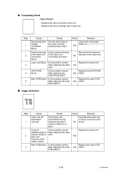
... laser unit connection failure Is the scanner harness of the laser unit. Yes 3-50 Confidential HVPS PCB failure Is the problem solved after replacing the laser unit? Yes Replace the drum unit. Reconnect the FG harness No ASSY between the laser unit and main PCB ASSY connected securely? Laser unit failure... Clean both electrodes. Replace the main PCB Yes ASSY. Replace the laser unit. ■ All black Step 1 2 3 4 5 6 7 Cause Check Result Remedy Corona wire failure Are the electrodes on the drum unit and machine body dirty? Replace the HVPS PCB Yes ASSY. Reconnect ...
... laser unit connection failure Is the scanner harness of the laser unit. Yes 3-50 Confidential HVPS PCB failure Is the problem solved after replacing the laser unit? Yes Replace the drum unit. Reconnect the FG harness No ASSY between the laser unit and main PCB ASSY connected securely? Laser unit failure... Clean both electrodes. Replace the main PCB Yes ASSY. Replace the laser unit. ■ All black Step 1 2 3 4 5 6 7 Cause Check Result Remedy Corona wire failure Are the electrodes on the drum unit and machine body dirty? Replace the HVPS PCB Yes ASSY. Reconnect ...


