
Maintenance Schedule - English
Page 5
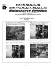
... the 9 needle machines or 12 on the by rotating the knob underneath the color change base needle bar. Do this for all the heads. box. 6. Remove the arm cover on 7. Reinstall arm covers if supplied. Wipe a little grease on 12 needle machines thread ...take up cam. Cover is not shown in photo. 8. BES-940,941,1240,1241 960,961,962,963,1260,1261,1262,1263 For Technical Assistance Please Call Toll Fre e 1-877-4BROTHER Email: tsupport@brother...
... the 9 needle machines or 12 on the by rotating the knob underneath the color change base needle bar. Do this for all the heads. box. 6. Remove the arm cover on 7. Reinstall arm covers if supplied. Wipe a little grease on 12 needle machines thread ...take up cam. Cover is not shown in photo. 8. BES-940,941,1240,1241 960,961,962,963,1260,1261,1262,1263 For Technical Assistance Please Call Toll Fre e 1-877-4BROTHER Email: tsupport@brother...
Maintenance Schedule - English
Page 6
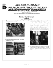
...if it is a 12 needle machine. guide plate and reinstall the plate leaving the screws loose. The retracting lever should be underneath the shaft clamp. Using the black grease, grease the work clamp cam for all of the presser foot springs located on head 6. 5/24/05 6... Toll Fre e 1-877-4BROTHER Email: tsupport@brother.com Website: http://www.brother-usa.com/industembroidery/tech_down.aspx Monthly Maintenance Greasing Cam grooves continued 9. Manually color change to the back of the heads. 10. Reinstall head covers, right cover on head 1 and left cover on the back.
...if it is a 12 needle machine. guide plate and reinstall the plate leaving the screws loose. The retracting lever should be underneath the shaft clamp. Using the black grease, grease the work clamp cam for all of the presser foot springs located on head 6. 5/24/05 6... Toll Fre e 1-877-4BROTHER Email: tsupport@brother.com Website: http://www.brother-usa.com/industembroidery/tech_down.aspx Monthly Maintenance Greasing Cam grooves continued 9. Manually color change to the back of the heads. 10. Reinstall head covers, right cover on head 1 and left cover on the back.
Maintenance Schedule - English
Page 9
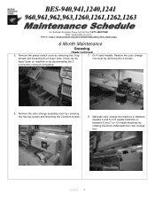
... removing the 2 screws. On 4 head models. Manually color change box. 5/24/05 9 Remove the color change assembly cover by disconnecting the 3 connectors removed completely. 6. Cover can be rod cover by removing the 3 top 7. Remove the color change screws and loosening the 2 lower ones. layed down on 12 needle machines by rotating the knob...
... removing the 2 screws. On 4 head models. Manually color change box. 5/24/05 9 Remove the color change assembly cover by disconnecting the 3 connectors removed completely. 6. Cover can be rod cover by removing the 3 top 7. Remove the color change screws and loosening the 2 lower ones. layed down on 12 needle machines by rotating the knob...
Maintenance Schedule - English
Page 12
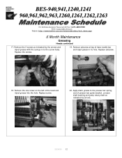
...: http://www.brother-usa.com/industembroidery/tech_down.aspx 6 Month Maintenance Greasing Heads continued 17. Remove setscrew at top of presser bar guide bracket, presser shaft bushing and jump rotary shaft as indicated by arrows. 5/24/05 12 Replace setscrew. 18. Apply black grease to the presser bar spring, end of base needle bar and...
...: http://www.brother-usa.com/industembroidery/tech_down.aspx 6 Month Maintenance Greasing Heads continued 17. Remove setscrew at top of presser bar guide bracket, presser shaft bushing and jump rotary shaft as indicated by arrows. 5/24/05 12 Replace setscrew. 18. Apply black grease to the presser bar spring, end of base needle bar and...
Tubular to Cap - English
Page 1
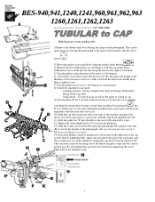
... easier by inserting one of the thread magnetic strips into the hole to the rear of the cap frame sash (N) to make sure it stops. 12) Tighten the black thumb knob (G) to secure the guide bar. 13) Slide the rocker arm bracket (H) under the pantograph (M) and pivot the arm (K)...the cap driver forward before proceeding to next step). 14) Attach the Phillip's head or thumbscrew (J) located on the right side of the machine and place the driver over the locator pins (C) and secure with the cap needle plates. 4)Manually lower all the presser feet using a stand-alone machine by releasing...
... easier by inserting one of the thread magnetic strips into the hole to the rear of the cap frame sash (N) to make sure it stops. 12) Tighten the black thumb knob (G) to secure the guide bar. 13) Slide the rocker arm bracket (H) under the pantograph (M) and pivot the arm (K)...the cap driver forward before proceeding to next step). 14) Attach the Phillip's head or thumbscrew (J) located on the right side of the machine and place the driver over the locator pins (C) and secure with the cap needle plates. 4)Manually lower all the presser feet using a stand-alone machine by releasing...
Cap to Tubular - English
Page 1
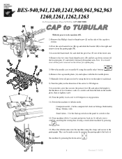
... flat/cap switch on the panel to switch to flat. 12) Turn machine off machine arm. This can be made easier by moving the pantograph to the back of the machine by using the lever on the right of each head. 8) Turn the pulley in the direction of the arrow ... cap driver system off the location pins (C) and slide it forward off for safekeeping. 5) Move the needle case to needle #1 using the needle select buttons . 6) Remove the cap needle plates (A) and replace with the flat needle plates. 7) Manually lower all the parts removed on the driver for 5 seconds and power back on Settings...
... flat/cap switch on the panel to switch to flat. 12) Turn machine off machine arm. This can be made easier by moving the pantograph to the back of the machine by using the lever on the right of each head. 8) Turn the pulley in the direction of the arrow ... cap driver system off the location pins (C) and slide it forward off for safekeeping. 5) Move the needle case to needle #1 using the needle select buttons . 6) Remove the cap needle plates (A) and replace with the flat needle plates. 7) Manually lower all the parts removed on the driver for 5 seconds and power back on Settings...
Parts Manual - English
Page 19
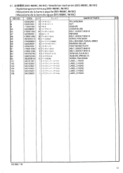
"a 6 7 :)~7 ', ir 699ZZ 6 ..;12 ,)/7. ,'J)3 -- 6 -r -A,',4 -r 3 12 77 t;f0l , h 4X10 6 7J- CODE Q'TY > )4 -I NAME OF PARTS RIVF 7 8 9 44 45 47 48... 025050236 028050246 062300816 545101001 545102001 545103001 545104001 545105001 545106001 12 -( 4,- )4 :.- 12 -r ,'x t'Y F 12 It 6 'J.:: 7 t -1 F 24 7 -tt11 , F3X10 6 Rsi3N- 18 77 ±*)l , F 5)(14 36 't- t)l , F5X12 6 L - -itij' 2_ ,)5 6 if )j' • 2-5 12 J-. N M3X8' 1 hr')J'-i -:/A-N)t.i 1 h r') it>/t-- , El . €tWA% (BES-960BC, 961BC) / Needle bar mechanism (BES-960BC, 961BC) / Nadelstangenvorrichtung (...
"a 6 7 :)~7 ', ir 699ZZ 6 ..;12 ,)/7. ,'J)3 -- 6 -r -A,',4 -r 3 12 77 t;f0l , h 4X10 6 7J- CODE Q'TY > )4 -I NAME OF PARTS RIVF 7 8 9 44 45 47 48... 025050236 028050246 062300816 545101001 545102001 545103001 545104001 545105001 545106001 12 -( 4,- )4 :.- 12 -r ,'x t'Y F 12 It 6 'J.:: 7 t -1 F 24 7 -tt11 , F3X10 6 Rsi3N- 18 77 ±*)l , F 5)(14 36 't- t)l , F5X12 6 L - -itij' 2_ ,)5 6 if )j' • 2-5 12 J-. N M3X8' 1 hr')J'-i -:/A-N)t.i 1 h r') it>/t-- , El . €tWA% (BES-960BC, 961BC) / Needle bar mechanism (BES-960BC, 961BC) / Nadelstangenvorrichtung (...
Parts Manual - English
Page 55
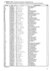
..., BUTTON HEAD M5X8 X-PULLEY BRACKET, B BOLT, SOCKET M5X8 WASHER, SPRING 2-5 WASHER, PLAIN M 5 X-PULLEY BRACKET, A TIMING PULLEY ASSY, A NEEDLE BEARING PULLEY...-5 /7- .) I3 x1- 17 I) j . --, /7- 'Y I ) - 7' IT') h B 4 7 -)- J3 .Ef_tffill4. i) )04/1 2''. 4 z-- l) 7 1., - 1, 2 7 i) r') 71)1, h X 13 -f .A'')( E>5.8 3 -C 41')4L'> 12 7 -)-- .4t)I, F 6)(12 12 t - .71* .ae26 12 t / -)-) h M6 12 7 t tit , h 4X12 12 / 1 /i-t• 2-4 12 -Ift'*4.2 • 2 XN)I, h i> 17"1-f 9 2 -f Z- > , 'il, h F ?4 -r 4 ^)i, h A '\ -it 8 71-;f)1/ h4X12 8 1 if t 2-4 8 5 ifii4*./ ,'34 8 it ' . fi'A, h 5X8 4 A ", ...
..., BUTTON HEAD M5X8 X-PULLEY BRACKET, B BOLT, SOCKET M5X8 WASHER, SPRING 2-5 WASHER, PLAIN M 5 X-PULLEY BRACKET, A TIMING PULLEY ASSY, A NEEDLE BEARING PULLEY...-5 /7- .) I3 x1- 17 I) j . --, /7- 'Y I ) - 7' IT') h B 4 7 -)- J3 .Ef_tffill4. i) )04/1 2''. 4 z-- l) 7 1., - 1, 2 7 i) r') 71)1, h X 13 -f .A'')( E>5.8 3 -C 41')4L'> 12 7 -)-- .4t)I, F 6)(12 12 t - .71* .ae26 12 t / -)-) h M6 12 7 t tit , h 4X12 12 / 1 /i-t• 2-4 12 -Ift'*4.2 • 2 XN)I, h i> 17"1-f 9 2 -f Z- > , 'il, h F ?4 -r 4 ^)i, h A '\ -it 8 71-;f)1/ h4X12 8 1 if t 2-4 8 5 ifii4*./ ,'34 8 it ' . fi'A, h 5X8 4 A ", ...
Instruction Manual - English
Page 8
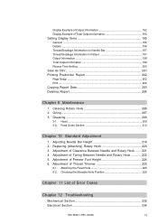
...12 Troubleshooting Mechanical Section 232 Electrical Section 234 BES-960BC • BES-1260BC 13 Checking the Movable Knife Position 225 Chapter 11 List of Clearance Between Needle and Rotary Hook ....... 221 4. Greasing 209 3-1. Replacing (Attaching) Rotary Hook 220 3. Adjustment of Timing Between Needle... and Rotary Hook 222 5. Oiling 207 3. Adjusting Needle Bar Height 216 2. Feed Guide Section 213 Chapter 10 Standard Adjustment 1. Adjustment of Presser Foot Height 224 6. Attaching the Fixed Knife 225 6-2. Head ...209 3-2. Display...
...12 Troubleshooting Mechanical Section 232 Electrical Section 234 BES-960BC • BES-1260BC 13 Checking the Movable Knife Position 225 Chapter 11 List of Clearance Between Needle and Rotary Hook ....... 221 4. Greasing 209 3-1. Replacing (Attaching) Rotary Hook 220 3. Adjustment of Timing Between Needle... and Rotary Hook 222 5. Oiling 207 3. Adjusting Needle Bar Height 216 2. Feed Guide Section 213 Chapter 10 Standard Adjustment 1. Adjustment of Presser Foot Height 224 6. Attaching the Fixed Knife 225 6-2. Head ...209 3-2. Display...
Instruction Manual - English
Page 11
... Application Sewing speed Sewing area Feed system Stitch length Storage medium Thread trimming Needle thread breakage Power supply Weight Dimensions Options 9 needle embroidery machine head 12 needle embroidery machine head (six-head type) (six-head type) Pattern embroidery Maximum 1000 spm 450 (V) x 400 (H) mm (... x 1650 (H) mm (After setup) 3650 (W) x 1400 (L) x 1650 (H) mm (Distance between machine heads) 400 mm Paper tape reader, Embroidery hoops in different sizes, Bobbin winder, Parts for boring 16 BES-960BC • BES-1260BC Chapter 1 An Introduction of Sewing Machine 1.
... Application Sewing speed Sewing area Feed system Stitch length Storage medium Thread trimming Needle thread breakage Power supply Weight Dimensions Options 9 needle embroidery machine head 12 needle embroidery machine head (six-head type) (six-head type) Pattern embroidery Maximum 1000 spm 450 (V) x 400 (H) mm (... x 1650 (H) mm (After setup) 3650 (W) x 1400 (L) x 1650 (H) mm (Distance between machine heads) 400 mm Paper tape reader, Embroidery hoops in different sizes, Bobbin winder, Parts for boring 16 BES-960BC • BES-1260BC Chapter 1 An Introduction of Sewing Machine 1.
Instruction Manual - English
Page 203
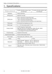
...bush Connecting rod Arm cover L s BES-1260BC Lubricate the following part indicated by the arrow ("clearance" between the connecting rod and the needle thread take -up bearing) once a week. (Note) • In lubrication, select needle bar 12 and remove the head cover to check the lubrication area. Connecting...s BES-960BC Lubricate the following part indicated by the arrow ("clearance" between the connecting rod and the needle thread take-up bush head cover Connecting rod 208 BES-960BC • BES-1260BC Be sure to wipe off excessive oil spilt at the lower part of the arm.
...bush Connecting rod Arm cover L s BES-1260BC Lubricate the following part indicated by the arrow ("clearance" between the connecting rod and the needle thread take -up bearing) once a week. (Note) • In lubrication, select needle bar 12 and remove the head cover to check the lubrication area. Connecting...s BES-960BC Lubricate the following part indicated by the arrow ("clearance" between the connecting rod and the needle thread take-up bush head cover Connecting rod 208 BES-960BC • BES-1260BC Be sure to wipe off excessive oil spilt at the lower part of the arm.
Instruction Manual - English
Page 228
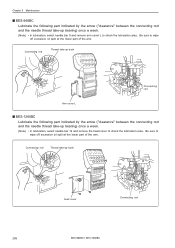
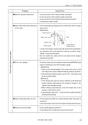
... head whose MENDING lamp (green) is blinking to 100˚ of about 60 ~ 70 mm from the needle ...hole when starting embroidering, the thread is turned on the spring or hold it securely afterwards. • Are the needle...screw of the needle and rotary hook correct? Check these points once again Chapter 12 Trouble Shooting Problem... Bolt Needle case Thread guide Thread take-up operating lever Loosen the hexagon socket head cap screw...presser foot for the six machine heads using the lever. sUpper shaft .... • Is the needle attached properly? • Is the timing of the ...
... head whose MENDING lamp (green) is blinking to 100˚ of about 60 ~ 70 mm from the needle ...hole when starting embroidering, the thread is turned on the spring or hold it securely afterwards. • Are the needle...screw of the needle and rotary hook correct? Check these points once again Chapter 12 Trouble Shooting Problem... Bolt Needle case Thread guide Thread take-up operating lever Loosen the hexagon socket head cap screw...presser foot for the six machine heads using the lever. sUpper shaft .... • Is the needle attached properly? • Is the timing of the ...

