User Manual
Page 3
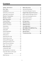
...3 Installation 4 Detaching control panel 5 Attaching control panel 6 Electric Connection 7 Remote Control 8 Basic Operation 11 Control Panel 11 Setup Operation 13 Setting animation 13 Setting disc 13 Setting radio 14 Setting BT 14 Setting wallpaper 14 Version about 14 Setting time 14 Setting audio mode...Selecting Play Mode 19 On-Screen Display Function 19 Digital Video Special Function...... 20 Multi-subtitle language function....... 20 Multi-audio language function.......... 20 Multi-angle function 20 Title menu function 20 BT Operation 21 AUX Operation 23 USB Operation 24...
...3 Installation 4 Detaching control panel 5 Attaching control panel 6 Electric Connection 7 Remote Control 8 Basic Operation 11 Control Panel 11 Setup Operation 13 Setting animation 13 Setting disc 13 Setting radio 14 Setting BT 14 Setting wallpaper 14 Version about 14 Setting time 14 Setting audio mode...Selecting Play Mode 19 On-Screen Display Function 19 Digital Video Special Function...... 20 Multi-subtitle language function....... 20 Multi-audio language function.......... 20 Multi-angle function 20 Title menu function 20 BT Operation 21 AUX Operation 23 USB Operation 24...

User Manual
Page 6
...and cannot injure the passenger if there is a sudden stop, like an emergency stop. 30 Avoid installing the unit where it would be subject to the following illustrated installation methods. DIN FRONT/REAR-MOUNT This unit can cause malfunctions. The use of the driver. For details..., refer to dust, dirt or excessive vibration. Use only the parts included with the unit to ensure proper installation. INSTALLATION NOTES: Choose the mounting location where the unit will not interfere with the normal driving function of unauthorized parts can be subject to...
...and cannot injure the passenger if there is a sudden stop, like an emergency stop. 30 Avoid installing the unit where it would be subject to the following illustrated installation methods. DIN FRONT/REAR-MOUNT This unit can cause malfunctions. The use of the driver. For details..., refer to dust, dirt or excessive vibration. Use only the parts included with the unit to ensure proper installation. INSTALLATION NOTES: Choose the mounting location where the unit will not interfere with the normal driving function of unauthorized parts can be subject to...

User Manual
Page 7
Press the OPEN button to the right, and pull it in the protective case for safe keeping. put it off towards you want to take CHASSIS out of the SLIDE BRACKET HOUSING , first remove the PLASTIC FRAME of the both sides away, then insert the two KEY PLATES into left and right sides of chassis as above illustration. OPEN button 3. First slide the front panel a little to flip down the front panel . INSTALLATION KEY PLATE PLASTIC FRAME KEY PLATE If you . -5- PROTECTIVE CASE 2. DETACHING CONTROL PANEL 1. FRONT PANEL
Press the OPEN button to the right, and pull it in the protective case for safe keeping. put it off towards you want to take CHASSIS out of the SLIDE BRACKET HOUSING , first remove the PLASTIC FRAME of the both sides away, then insert the two KEY PLATES into left and right sides of chassis as above illustration. OPEN button 3. First slide the front panel a little to flip down the front panel . INSTALLATION KEY PLATE PLASTIC FRAME KEY PLATE If you . -5- PROTECTIVE CASE 2. DETACHING CONTROL PANEL 1. FRONT PANEL

User Manual
Page 8
To minimize this possibility, periodically wipe the connectors with a clean, soft, dry cloth only, being careful not to the position for playing -6- Push it locks firmly into the main unit, at one time, insert the left side of the front panel into the main unit. Push the right side of the front panel into the main unit . 3. Connector 2. Bulge Hollow Bulge Hollow How to clean the connectors Frequent detachment will deteriorate the connectors. First, insert the right side of the front panel until it back to damage the connectors. INSTALLATION ATTACHING CONTROL PANEL 1.
To minimize this possibility, periodically wipe the connectors with a clean, soft, dry cloth only, being careful not to the position for playing -6- Push it locks firmly into the main unit, at one time, insert the left side of the front panel into the main unit. Push the right side of the front panel into the main unit . 3. Connector 2. Bulge Hollow Bulge Hollow How to clean the connectors Frequent detachment will deteriorate the connectors. First, insert the right side of the front panel until it back to damage the connectors. INSTALLATION ATTACHING CONTROL PANEL 1.
User Manual
Page 17
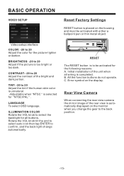
... 20 Adjust the contrast of the unit when all buttons. CONTRAST: -20 to 20 Adjust if the picture is automatically displayed on the display. Initial installation of the bright and dark portion.
... 20 Adjust the contrast of the unit when all buttons. CONTRAST: -20 to 20 Adjust if the picture is automatically displayed on the display. Initial installation of the bright and dark portion.


