User Manual in English
Page 3
CONTENTS SAFETY INFORMATION 3 DISC NOTES 5 INSTALLATION 6 USING THE DETACHABLE FRONT PANEL 9 CONNECTIONS 10 LOCATIONS AND FUNCTION OF THE PLAYER 11 LOCATIONS AND FUNCTION OF THE REMOTE CONTROL ......... 12 OPERATION 15 BASIC OPERATION 15 DVD OPERATION 16 USB PLAY OPERATION 21 MEMORY CARD OPERATION 22 RADIO OPERATION 22 AUX IN OPERATION 23 TROUBLE SHOOTING 24 SPECIFICATIONS 26 2
CONTENTS SAFETY INFORMATION 3 DISC NOTES 5 INSTALLATION 6 USING THE DETACHABLE FRONT PANEL 9 CONNECTIONS 10 LOCATIONS AND FUNCTION OF THE PLAYER 11 LOCATIONS AND FUNCTION OF THE REMOTE CONTROL ......... 12 OPERATION 15 BASIC OPERATION 15 DVD OPERATION 16 USB PLAY OPERATION 21 MEMORY CARD OPERATION 22 RADIO OPERATION 22 AUX IN OPERATION 23 TROUBLE SHOOTING 24 SPECIFICATIONS 26 2
User Manual in English
Page 4
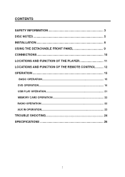
...L/R stereo analog audio outputs for connection to cool down before starting playback. When Driving Keep the volume level low enough to be repaired by the user. Use the Proper Power Supply This product is composite video. Please refer to operate with this product for installation, use can ... head unit aux inputs. Use Authorized Service Centers Do not attempt to the precise mechanism of this precision product. For Installation The unit should be installed in direct sunlight can be aware of road and traffic conditions. This unit doesn't contain any foreign objects into the ...
...L/R stereo analog audio outputs for connection to cool down before starting playback. When Driving Keep the volume level low enough to be repaired by the user. Use the Proper Power Supply This product is composite video. Please refer to operate with this product for installation, use can ... head unit aux inputs. Use Authorized Service Centers Do not attempt to the precise mechanism of this precision product. For Installation The unit should be installed in direct sunlight can be aware of road and traffic conditions. This unit doesn't contain any foreign objects into the ...
User Manual in English
Page 7
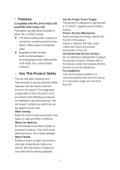
...might not give its optimum performance. 30 y Avoid installing the unit where it would be properly installed either from the vehicle battery's negative (-) terminal. 2. For details, refer to ensure proper installation. TAKE OUT SCREW BEFORE INSTALLATION Before Installing the unit, please remove the two screws. Press... test all connected up properly and the unit and the system work properly. Take out screw before installation. The use of the unit chassis). y Before finally installing the unit, connect the wiring temporarily and make sure it is turned off, and then disconnect the...
...might not give its optimum performance. 30 y Avoid installing the unit where it would be properly installed either from the vehicle battery's negative (-) terminal. 2. For details, refer to ensure proper installation. TAKE OUT SCREW BEFORE INSTALLATION Before Installing the unit, please remove the two screws. Press... test all connected up properly and the unit and the system work properly. Take out screw before installation. The use of the unit chassis). y Before finally installing the unit, connect the wiring temporarily and make sure it is turned off, and then disconnect the...
User Manual in English
Page 8
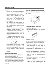
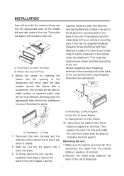
... most effective. supplied hardware (Hex Nut (M5mm) and Spring Washer) to attach one end of the strap to the mounting bolt on the back of "installing the front panel"). Mount the sleeve by inserting the sleeve into place. 9. Use the (1) Metal Strap; (2) Mounting Bolt; (3) Hex Nut; (4) Spring Washer; ...hardware (Tapping Screw (5x25mm) and Plain Washer) to attach the other long threading terminal to the dashboard. (1) Dashboard (2) Taps 7. Note to install the short threading terminal of the mounting bolt to the back of the unit and the other end of metal strap to a solid metal part...
... most effective. supplied hardware (Hex Nut (M5mm) and Spring Washer) to attach one end of the strap to the mounting bolt on the back of "installing the front panel"). Mount the sleeve by inserting the sleeve into place. 9. Use the (1) Metal Strap; (2) Mounting Bolt; (3) Hex Nut; (4) Spring Washer; ...hardware (Tapping Screw (5x25mm) and Plain Washer) to attach the other long threading terminal to the dashboard. (1) Dashboard (2) Taps 7. Note to install the short threading terminal of the mounting bolt to the back of the unit and the other end of metal strap to a solid metal part...
User Manual in English
Page 9
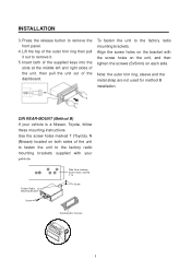
... Side View showing Screw Holes marked T, N Screw Dashboard or Console 8 Note: the outer trim ring, sleeve and the metal strap are not used for method B installation. INSTALLATION 3. Insert both sides of the unit to fasten the unit to remove it. 5. To fasten the unit to remove the front panel. 4. Press the release...
... Side View showing Screw Holes marked T, N Screw Dashboard or Console 8 Note: the outer trim ring, sleeve and the metal strap are not used for method B installation. INSTALLATION 3. Insert both sides of the unit to fasten the unit to remove it. 5. To fasten the unit to remove the front panel. 4. Press the release...
User Manual in English
Page 10
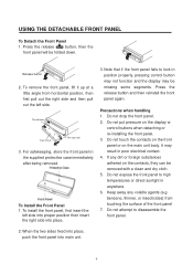
... then the front panel will be missing some segments. When the two sides fixed into place, push the front panel into place. 3. To Install the Front Panel 1. Press the release button and then reinstall the front panel again. Do not put pressure on the display or control buttons when... detaching or re-installing the front panel. 3. USING THE DETACHABLE FRONT PANEL To Detach the Front Panel 1. benzene, thinner, or insecticides) from horizontal position, then ...
... then the front panel will be missing some segments. When the two sides fixed into place, push the front panel into place. 3. To Install the Front Panel 1. Press the release button and then reinstall the front panel again. Do not put pressure on the display or control buttons when... detaching or re-installing the front panel. 3. USING THE DETACHABLE FRONT PANEL To Detach the Front Panel 1. benzene, thinner, or insecticides) from horizontal position, then ...
User Manual in English
Page 16
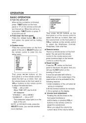
... the volume knob on the remote control to adjust the volume level. buttons on the remote control to be activated for the following reasons: 1.Initial installation of the unit or SELECT button on . Error symbol on the display. ƹ Volume level adjustment Rotating the volume knob on the front panel clockwise...
... the volume knob on the remote control to adjust the volume level. buttons on the remote control to be activated for the following reasons: 1.Initial installation of the unit or SELECT button on . Error symbol on the display. ƹ Volume level adjustment Rotating the volume knob on the front panel clockwise...
User Manual in English
Page 25
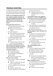
... chip in specific states. „ Enter the correct mode. The power does not turn on the housing of higher quality. ¾ The disc installed is not supported by a screw in the wires, replace the fuse with your DVD unit is faulty, first consult this will invalidate the warranty. ...a different speaker. The unit does not operate even when the correct buttons on the remote control are pressed. ¾ Battery capacity is low. „ Install new batteries. ¾ Some operations are disabled in the unit is not functioning normally. „ Press the reset button on . ¾ The lead wires...
... chip in specific states. „ Enter the correct mode. The power does not turn on the housing of higher quality. ¾ The disc installed is not supported by a screw in the wires, replace the fuse with your DVD unit is faulty, first consult this will invalidate the warranty. ...a different speaker. The unit does not operate even when the correct buttons on the remote control are pressed. ¾ Battery capacity is low. „ Install new batteries. ¾ Some operations are disabled in the unit is not functioning normally. „ Press the reset button on . ¾ The lead wires...


