
Brochure
Page 1
.... Using the proprietary pan/tilt/rotation mechanism, installers can be extreme. The day/night feature ensures the highest image quality possible at any decor. Six distinct pre-programmed operational modes are protected against water and dust to monochrome. Recall the mode that suits your application for outdoor use . Functions Detail in Extreme Lighting In harsh lighting, the difference between the brightest and the darkest parts...
.... Using the proprietary pan/tilt/rotation mechanism, installers can be extreme. The day/night feature ensures the highest image quality possible at any decor. Six distinct pre-programmed operational modes are protected against water and dust to monochrome. Recall the mode that suits your application for outdoor use . Functions Detail in Extreme Lighting In harsh lighting, the difference between the brightest and the darkest parts...

Brochure
Page 2
... Technology Bilinx is dominant. Switching between modes is detected, alarms can be displayed in the video signal of the scene to test and fault-find cables. • A multi-language On-Screen Display (OSD) increases user compatibility. When motion is easy via the Bilinx coaxial control interface. Pre-program any part of all lighting conditions reveals details previously unseen. 2X-Dynamic and SmartBLC Using 2X-Dynamic technology, pixel...
... Technology Bilinx is dominant. Switching between modes is detected, alarms can be displayed in the video signal of the scene to test and fault-find cables. • A multi-language On-Screen Display (OSD) increases user compatibility. When motion is easy via the Bilinx coaxial control interface. Pre-program any part of all lighting conditions reveals details previously unseen. 2X-Dynamic and SmartBLC Using 2X-Dynamic technology, pixel...
Brochure
Page 3
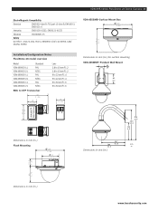
VDN-498 Series FlexiDome 2X Dome Camera | 3 Electro Magnetic Compatibility Emission EN55022 class B, FCC part 15 class B, EN6100-3, EN50121-4 Immunity EN50130-4 (CE), EN50121-4 (CE) Vibration IEC60068-2-6 Safety UL1950-1, CSA 22.2 No. 950-1, EN60950-1 (CE), UL60950, CAN/ CSA No. 60950 130.5 5.14 VDA-455SMB-Surface Mount Box 158 6.22 Installation/Configuration Notes FlexiDome 2X model overview Model VDN-498V03-11 VDN-498V03-21 VDN-498V09-11 VDN-498V09-21 VDN-498V06-11...
VDN-498 Series FlexiDome 2X Dome Camera | 3 Electro Magnetic Compatibility Emission EN55022 class B, FCC part 15 class B, EN6100-3, EN50121-4 Immunity EN50130-4 (CE), EN50121-4 (CE) Vibration IEC60068-2-6 Safety UL1950-1, CSA 22.2 No. 950-1, EN60950-1 (CE), UL60950, CAN/ CSA No. 60950 130.5 5.14 VDA-455SMB-Surface Mount Box 158 6.22 Installation/Configuration Notes FlexiDome 2X model overview Model VDN-498V03-11 VDN-498V03-21 VDN-498V09-11 VDN-498V09-21 VDN-498V06-11...
Brochure
Page 4
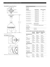
...Power Consumption CCD Type 400 mA (12 VDC) 350 mA (24 VAC) 1/3-inch interline, WDR dual shutter Active Pixels PAL Model: NTSC Model 752 x 582 768 x 494 Sensitivity (3200 K, scene reflectivity 89%, transmission 68%) Full video (100 IRE) Usable picture Usable picture (50 IRE) (30 IRE) VDN-498V03 (F1.2) Color... 0.014 lx (0.001fc) VDN-498V09 (F1.4) Color 2.7 lx (0.26 fc) 0.69 lx (0.064 fc) 0.321 lx (0.03 fc) Color + SensUp 10x 0.27 lx (0.026 fc) 0.069 lx (0.0064 fc) 0.032 lx (0.003 fc) 4 | VDN-498 Series FlexiDome 2X Dome Camera VDA-455PMT-Pendant Pipe Mount 88.9 3.5 88.9 3.5...
...Power Consumption CCD Type 400 mA (12 VDC) 350 mA (24 VAC) 1/3-inch interline, WDR dual shutter Active Pixels PAL Model: NTSC Model 752 x 582 768 x 494 Sensitivity (3200 K, scene reflectivity 89%, transmission 68%) Full video (100 IRE) Usable picture Usable picture (50 IRE) (30 IRE) VDN-498V03 (F1.2) Color... 0.014 lx (0.001fc) VDN-498V09 (F1.4) Color 2.7 lx (0.26 fc) 0.69 lx (0.064 fc) 0.321 lx (0.03 fc) Color + SensUp 10x 0.27 lx (0.026 fc) 0.069 lx (0.0064 fc) 0.032 lx (0.003 fc) 4 | VDN-498 Series FlexiDome 2X Dome Camera VDA-455PMT-Pendant Pipe Mount 88.9 3.5 88.9 3.5...

Brochure
Page 5
... Reduction Sharpness SmartBLC AGC Peak White Invert White Balance Alarm Output Synchronization Cable Compensation Camera ID Test Pattern Generator Modes Remote Control Video Motion Detection Privacy Masking Controls 540 TVL >50 dB Composite video 1 Vpp, 75 ohm Internal, Line Lock Auto (1/50 [1/60] to 1/10000) selectable Auto (1/50 [1/60] to 1/50000) automatic flickerless, fixed selectable Adjustable from Off up to 10x Color, Mono, Auto Automatic continuous, Off XF-Dynamic...
... Reduction Sharpness SmartBLC AGC Peak White Invert White Balance Alarm Output Synchronization Cable Compensation Camera ID Test Pattern Generator Modes Remote Control Video Motion Detection Privacy Masking Controls 540 TVL >50 dB Composite video 1 Vpp, 75 ohm Internal, Line Lock Auto (1/50 [1/60] to 1/10000) selectable Auto (1/50 [1/60] to 1/50000) automatic flickerless, fixed selectable Adjustable from Off up to 10x Color, Mono, Auto Automatic continuous, Off XF-Dynamic...
User Manual
Page 3
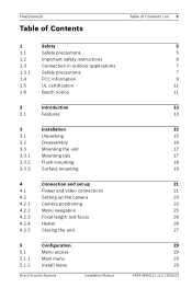
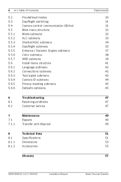
... safety instructions Connection in outdoor applications Safety precautions FCC information UL certification Bosch notice 2 Introduction 2.1 Features 3 3.1 3.2 3.3 3.3.1 3.3.2 3.3.3 Installation Unpacking Disassembly Mounting the unit Mounting tips Flush mounting Surface mounting 4 4.1 4.2 4.2.1 4.2.2 4.2.3 4.2.4 4.2.5 Connection and set-up Power and video connections Setting up the camera Camera positioning Menu navigation Focal length and focus Heater Closing the unit 5 5.1 5.1.1 5.1.2 Configuration Menu access Main menu Install menu Bosch Security Systems Installation Manual...
... safety instructions Connection in outdoor applications Safety precautions FCC information UL certification Bosch notice 2 Introduction 2.1 Features 3 3.1 3.2 3.3 3.3.1 3.3.2 3.3.3 Installation Unpacking Disassembly Mounting the unit Mounting tips Flush mounting Surface mounting 4 4.1 4.2 4.2.1 4.2.2 4.2.3 4.2.4 4.2.5 Connection and set-up Power and video connections Setting up the camera Camera positioning Menu navigation Focal length and focus Heater Closing the unit 5 5.1 5.1.1 5.1.2 Configuration Menu access Main menu Install menu Bosch Security Systems Installation Manual...
User Manual
Page 4
... 5.6.4 5.6.5 5.6.6 Pre-defined modes Day/Night switching Camera control communication (Bilinx) Main menu structure Mode submenu ALC submenu Shutter/AGC submenu Day/Night submenu Enhance / Dynamic Engine submenu Color submenu VMD submenu Install menu structure Language submenu Connections submenu Test signal submenu Camera ID submenu Privacy masking submenu Defaults submenu 6 Troubleshooting 6.1 Resolving problems 6.2 Customer service 7 7.1 7.1.1 Maintenance Repairs Transfer and disposal 8 8.1 8.1.1 8.1.2 Technical Data Specifications Dimensions Accessories Glossary FlexiDome2X 30...
... 5.6.4 5.6.5 5.6.6 Pre-defined modes Day/Night switching Camera control communication (Bilinx) Main menu structure Mode submenu ALC submenu Shutter/AGC submenu Day/Night submenu Enhance / Dynamic Engine submenu Color submenu VMD submenu Install menu structure Language submenu Connections submenu Test signal submenu Camera ID submenu Privacy masking submenu Defaults submenu 6 Troubleshooting 6.1 Resolving problems 6.2 Customer service 7 7.1 7.1.1 Maintenance Repairs Transfer and disposal 8 8.1 8.1.1 8.1.2 Technical Data Specifications Dimensions Accessories Glossary FlexiDome2X 30...

User Manual
Page 7
... or at 24 VAC. Bosch Security Systems Installation Manual AR18-08-B010 | v1.0 | 2009.03 The unit is intended to operate at the unit's power supply terminals. models only: Section 810 of the National Electrical Code, ANSI/NFPA No.70, provides information regarding installation of water. refer to the National Electrical Code Article 820 regarding proper grounding of the mount and supporting structure, grounding of...
... or at 24 VAC. Bosch Security Systems Installation Manual AR18-08-B010 | v1.0 | 2009.03 The unit is intended to operate at the unit's power supply terminals. models only: Section 810 of the National Electrical Code, ANSI/NFPA No.70, provides information regarding installation of water. refer to the National Electrical Code Article 820 regarding proper grounding of the mount and supporting structure, grounding of...
User Manual
Page 9
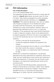
... user's authority to part 15 of the following booklet, prepared by turning the equipment off and on a circuit different from that interference will not occur in a particular installation. increase the separation between the equipment and receiver; - The user may cause harmful interference to Identify and Resolve Radio-TV Interference Problems. This booklet is connected; - reorient or relocate the receiving...
... user's authority to part 15 of the following booklet, prepared by turning the equipment off and on a circuit different from that interference will not occur in a particular installation. increase the separation between the equipment and receiver; - The user may cause harmful interference to Identify and Resolve Radio-TV Interference Problems. This booklet is connected; - reorient or relocate the receiving...
User Manual
Page 13
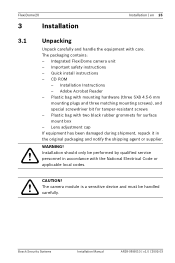
Important safety instructions - Plastic bag with mounting hardware (three SX8 4.5-6 mm mounting plugs and three matching mounting screws), and special screwdriver bit for surface mount box - FlexiDome2X 3 Installation Installation | en 15 3.1 ! Quick install instructions - CD ROM - CAUTION! ! Integrated FlexiDome camera unit - Installation Instructions - Lens adjustment cap If equipment has been damaged during shipment, repack it in accordance with care. Bosch Security Systems Installation Manual AR18-08-B010 | v1.0 | 2009.03 Installation should only...
Important safety instructions - Plastic bag with mounting hardware (three SX8 4.5-6 mm mounting plugs and three matching mounting screws), and special screwdriver bit for surface mount box - FlexiDome2X 3 Installation Installation | en 15 3.1 ! Quick install instructions - CD ROM - CAUTION! ! Integrated FlexiDome camera unit - Installation Instructions - Lens adjustment cap If equipment has been damaged during shipment, repack it in accordance with care. Bosch Security Systems Installation Manual AR18-08-B010 | v1.0 | 2009.03 Installation should only...
User Manual
Page 19
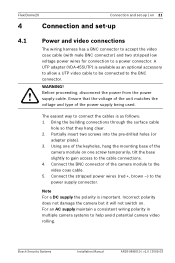
... mounting base of the camera module on . For an AC supply maintain a consistent wiring polarity in multiple camera systems to the cable connections. 4. FlexiDome2X Connection and set-up | en 21 4 Connection and set-up 4.1 ! Before proceeding, disconnect the power from the power supply cable. Ensure that they hang clear. 2. Connect the BNC connector of the power supply being used. Bosch Security Systems Installation Manual AR18-08-B010 | v1.0 | 2009.03 Bring the building connections through the surface cable...
... mounting base of the camera module on . For an AC supply maintain a consistent wiring polarity in multiple camera systems to the cable connections. 4. FlexiDome2X Connection and set-up | en 21 4 Connection and set-up 4.1 ! Before proceeding, disconnect the power from the power supply cable. Ensure that they hang clear. 2. Connect the BNC connector of the power supply being used. Bosch Security Systems Installation Manual AR18-08-B010 | v1.0 | 2009.03 Bring the building connections through the surface cable...

User Manual
Page 22
... adjusted along the pan axis (A), rotate the camera module in the base. For horizontal adjustment along three axes. AR18-08-B010 | v1.0 | 2009.03 Installation Manual Bosch Security Systems Avoid bright lights in operating and non-operating conditions. For vertical adjustment along the twist axis (C) to the desired position by performing the following steps: - Navigation buttons (5) 5. Focus A. CCD image sensors are highly sensitive and require special care ! Set the camera...
... adjusted along the pan axis (A), rotate the camera module in the base. For horizontal adjustment along three axes. AR18-08-B010 | v1.0 | 2009.03 Installation Manual Bosch Security Systems Avoid bright lights in operating and non-operating conditions. For vertical adjustment along the twist axis (C) to the desired position by performing the following steps: - Navigation buttons (5) 5. Focus A. CCD image sensors are highly sensitive and require special care ! Set the camera...

User Manual
Page 24
... monitor. 4.2.4 Heater When using the camera at ambient temperatures below 0°C (+32°F). Do not change this selection as when the dome is in a special mode for adjusting focus. 3. Re-adjust the focal length if necessary. 6. AR18-08-B010 | v1.0 | 2009.03 Installation Manual Bosch Security Systems Connect a monitor or other display device to either the camera's BNC connector or to Auto in the Install menu. Tighten both screws. 8. The heater turns...
... monitor. 4.2.4 Heater When using the camera at ambient temperatures below 0°C (+32°F). Do not change this selection as when the dome is in a special mode for adjusting focus. 3. Re-adjust the focal length if necessary. 6. AR18-08-B010 | v1.0 | 2009.03 Installation Manual Bosch Security Systems Connect a monitor or other display device to either the camera's BNC connector or to Auto in the Install menu. Tighten both screws. 8. The heater turns...

User Manual
Page 26
... than 1 second. The camera implements your changes, you to make configuration easier. Use the up/down, right/left buttons for less than 1 second. The Main menu allows you can be selected directly or submenus for further adjustments. Up button Menu/Select button (center) Right button Down button Left button Main menu To access the Main menu, press the menu/select button (center) for navigation. Bosch Security Systems Installation Manual AR18-08-B010...
... than 1 second. The camera implements your changes, you to make configuration easier. Use the up/down, right/left buttons for less than 1 second. The Main menu allows you can be selected directly or submenus for further adjustments. Up button Menu/Select button (center) Right button Down button Left button Main menu To access the Main menu, press the menu/select button (center) for navigation. Bosch Security Systems Installation Manual AR18-08-B010...

User Manual
Page 30
... video control. a negative value is enabled. For most scenes it should remain at the default value. Some ALC adjustment may cause oscillations). ALC speed Slow, medium, fast Adjusts the speed of the video level control loop. The camera output is more priority to an analog system (matrix switcher or monitor. A positive value is optimized for low-light conditions; A negative value gives more useful for connection to average light...
... video control. a negative value is enabled. For most scenes it should remain at the default value. Some ALC adjustment may cause oscillations). ALC speed Slow, medium, fast Adjusts the speed of the video level control loop. The camera output is more priority to an analog system (matrix switcher or monitor. A positive value is optimized for low-light conditions; A negative value gives more useful for connection to average light...

User Manual
Page 32
... at a lower light level. Bosch Security Systems Installation Manual AR18-08-B010 | v1.0 | 2009.03 the camera switches the IR cut -off depending on moving objects. the camera always produces a color signal regardless of the camera is normal camera behavior. A high (positive) value means that the camera switches to +15 Sets the video level in the picture. It may appear in Auto mode at a higher light level. the IR...
... at a lower light level. Bosch Security Systems Installation Manual AR18-08-B010 | v1.0 | 2009.03 the camera switches the IR cut -off depending on moving objects. the camera always produces a color signal regardless of the camera is normal camera behavior. A high (positive) value means that the camera switches to +15 Sets the video level in the picture. It may appear in Auto mode at a higher light level. the IR...

User Manual
Page 38
...-screen display (OSD) language Sets synchronization parameters. When finished adjusting, press the Up or Down navigation button to close the Install menu and open the Install menu again. Bosch Security Systems Installation Manual AR18-08-B010 | v1.0 | 2009.03 Adjust the focus as described in Section 4.2.3 Focal length and focus. Connection parameters Test patterns and texts Select to access ID submenu Sets up a masking area Returns all settings for all modes...
...-screen display (OSD) language Sets synchronization parameters. When finished adjusting, press the Up or Down navigation button to close the Install menu and open the Install menu again. Bosch Security Systems Installation Manual AR18-08-B010 | v1.0 | 2009.03 Adjust the focus as described in Section 4.2.3 Focal length and focus. Connection parameters Test patterns and texts Select to access ID submenu Sets up a masking area Returns all settings for all modes...

User Manual
Page 43
... the camera function. Faulty cable connections. Faulty installation. Connect a local monitor to remote location. When using DC power ensure that it can be referenced for warranty or repair. established, no image transmission. Note down all cables, plugs, contacts and connections. 6.2 Customer service If you identify the causes of the firmware and other status information can be seen when the unit starts or by opening the Install menu. No connection The unit's configuration...
... the camera function. Faulty cable connections. Faulty installation. Connect a local monitor to remote location. When using DC power ensure that it can be referenced for warranty or repair. established, no image transmission. Note down all cables, plugs, contacts and connections. 6.2 Customer service If you identify the causes of the firmware and other status information can be seen when the unit starts or by opening the Install menu. No connection The unit's configuration...
User Manual
Page 44
... according to your dealer's technical service center. Ensure that must be passed-on together with this installation guide. Never open the casing of professionally or taken to law. The unit does not contain any user serviceable parts. The unit contains environmentally hazardous materials that all maintenance or repair work is performed only by qualified personnel (electrical engineering or network technology specialists).
... according to your dealer's technical service center. Ensure that must be passed-on together with this installation guide. Never open the casing of professionally or taken to law. The unit does not contain any user serviceable parts. The unit contains environmentally hazardous materials that all maintenance or repair work is performed only by qualified personnel (electrical engineering or network technology specialists).
User Manual
Page 45
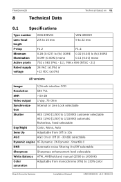
... VAC (±10%) or +12 VDC (±10%) All versions Imager 1/3-inch interline CCD Resolution 540 TVL SNR > 50 dB Video output 1 Vpp, 75 Ohm Synchronization Internal or Line Lock selectable Shutter AES (1/60 [1/50] to 1/10000) customer selectable AES (1/60 [1/50] to 1/15000) automatic flickerless, fixed selectable Day/Night Color, Mono, Auto Sens Up Adjustable from Off to 10x AGC...
... VAC (±10%) or +12 VDC (±10%) All versions Imager 1/3-inch interline CCD Resolution 540 TVL SNR > 50 dB Video output 1 Vpp, 75 Ohm Synchronization Internal or Line Lock selectable Shutter AES (1/60 [1/50] to 1/10000) customer selectable AES (1/60 [1/50] to 1/15000) automatic flickerless, fixed selectable Day/Night Color, Mono, Auto Sens Up Adjustable from Off to 10x AGC...


