Bosch LTC 1461-21 Support and Manuals
Get Help and Manuals for this Bosch item

View All Support Options Below
Free Bosch LTC 1461-21 manuals!
Problems with Bosch LTC 1461-21?
Ask a Question
Free Bosch LTC 1461-21 manuals!
Problems with Bosch LTC 1461-21?
Ask a Question
Popular Bosch LTC 1461-21 Manual Pages
Installation Manual - Page 2

..." within the product's enclosure that produce heat.
Bosch Security Systems | 2005-02 | V2.0 Refer servicing to .
4. FlexidomeXT | Installation Manual
EN | 2
SAFETY PRECAUTIONS
Danger
The lightning flash with dry cloth. 7. Follow all Warnings: All warnings on the unit and in the literature accompanying the appliance. Heed all Instructions: All operating and use this apparatus near...
Installation Manual - Page 3

... as they exit from the type of any service or repairs to this can fall into such power lines or circuits. 14. FlexidomeXT | Installation Manual
EN | 3
8. Power Sources: This unit should not be operated only from the apparatus.
9. Unauthorized substitutions may touch dangerous voltage points or shortout parts that the unit is in any kind on...
Installation Manual - Page 5

... supply voltage Lens
CCD type
LTC 136x/10
CCIR Monochrome
LTC 146x/11
PAL Color
LTC 136x/20
EIA Monochrome
LTC 146x/21
NTSC Color
12~24 VAC, 50Hz or 12~33 VDC
12~24 VAC, 60Hz or 12~33 VDC
LTC 1361 and LTC 1461: 2.8-6 mm F1.4-360 LTC 1462: 2-4 mm F1.4-360; The packaging contains: • Integrated FlexidomeXT camera/housing unit • Mounting hardware...
Installation Manual - Page 6

Bosch Security Systems | 2005-02 | V2.0 FlexidomeXT | Installation Manual
EN | 6
3 Disassembly
The FlexidomeXT camera/housing unit consists of the liner.
Do not drop when ...the screw in place.) • Rotate the trim ring counterclockwise and remove it. • Unscrew the dome counterclockwise and remove it from the base
together with the sealing ring. • Remove the inner liner by...
Installation Manual - Page 7

...)
Mounting base
Bosch Security Systems | 2005-02 | V2.0
Tips • Use the mounting base as a template to mark the position of the four
screw holes and the center hole for the keyholes and use the optional raised mounting base (LTC 1347) and mount the FlexidomeXT onto this base.
Figure 4-1 Rear connection - FlexidomeXT | Installation Manual
EN | 7
4 Mounting...
Installation Manual - Page 9
...Conduit grommet
Wires
Raised mounting base (LTC 1347/00) Camera unit and base
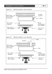
Figure 4-5 Raised mounting - rear connection
Conduit
Solid surface (four pre-drilled 8mm holes)
Four screws (supplied)
Four screws (M5, supplied)
Wires
Cap
Raised mounting base (LTC 1347/00) Camera unit and base
Bosch Security Systems | 2005-02 | V2.0 FlexidomeXT | Installation Manual
Figure 4-4 Raised mounting -
Installation Manual - Page 10

Bosch Security Systems | 2005-02 | V2.0 rear connection When using the raised mounting base ...to the mounting base. • Run the power and video wires through separate rubber grommets into
the connection box area. FlexidomeXT | Installation Manual
EN | 10
Raised mounting -
side connection When using the raised mounting base with a side connection: • Remove the cap covering ...
Installation Manual - Page 11
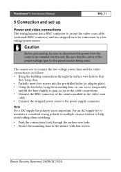
...insert two screws into the unit. Bosch Security Systems | 2005-02 | V2.0 For an AC supply try to maintain a consistent wiring polarity in multiple camera systems to help avoid rolling when ...unit is of the camera module to the video coax
cable. • Connect the stripped power wires to the power supply connector. FlexidomeXT | Installation Manual
EN | 11
5 Connection and set-up
Power and ...
Installation Manual - Page 12

Focus Focal length
Monitor jack Thumbwheels
DIP switches
V-phase adjust
Bosch Security Systems | 2005-02 | V2.0 This jack provides a composite video signal, via the optional cable S1460 (2.5 mm plug to help set up the camera.
FlexidomeXT | Installation Manual
EN | 12
Setting up the camera
You may connect a monitor to the miniature 2.5 mm jack on the printed circuit board cover...
Installation Manual - Page 13

... position of the camera is set the following steps: • For horizontal adjustment, rotate the camera module in the base. Bosch Security Systems | 2005-02 | V2.0
Avoid bright lights in the field of view of the image corresponds to synronize the picture with other AC powered cameras in operating and nonoperating conditions. FlexidomeXT | Installation Manual
EN | 13
DIP...
Installation Manual - Page 14
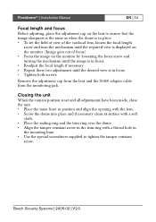
...When the camera position is set the field...dome is in
the mounting base. • Use the special screwdriver supplied to tighten the tamper resistant
screw.
FlexidomeXT | Installation Manual...view is in place. • To set and all adjustments have been made, ...dome into place and if necessary clean its surface with a soft
cloth. • Place the sealing ring and the trim ring over the dome...
Installation Manual - Page 15
...
DC iris FlexidomeXT | Installation Manual
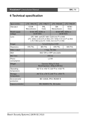
6 Technical specification
EN | 15
Type number Standard
Rated supply voltage Lens
Imager Resolution Video output BLC ALC lens Power consumption Weight
Operating temperature Storage temperature Environmental protection Impact protection
LTC 136x/10 LTC 146x/11 LTC 136x/20 LTC 146x/21
CCIR Monochrome
PAL Color
EIA Monochrome
NTSC Color
12-24...
Installation Manual - Page 16

FlexidomeXT | Installation Manual
Dimensions (mm)
Figure 6-1 FlexidomeXT
(4.65")
118
EN | 16
(4.65")
118
(0.77") (0.35") (2.28")
58
20 9
93 (3.66")
144
(5.67")
Bosch Security Systems | 2005-02 | V2.0
Installation Manual - Page 17

FlexidomeXT | Installation Manual
Figure 6-2 FlexidomeXT with LTC 1347 mounting base
(2.2")
56
EN | 17
(1.42")
3 6
11 8
(4.65")
87
(3.43")
3 0
(1.18")
146
(5.75")
Bosch Security Systems | 2005-02 | V2.0
Installation Manual - Page 18

FlexidomeXT | Installation Manual
EN | 18
Bosch Security Systems | 2005-02 | V2.0
Bosch LTC 1461-21 Reviews
We have not received any reviews for Bosch yet.