Operation Manual
Page 1
IP Camera 200 Series NBC-255-P en Installation and Operation Manual
IP Camera 200 Series NBC-255-P en Installation and Operation Manual

Operation Manual
Page 3
IP Camera 200 Series Table of Contents 1 Safety 1.1 Safety precautions 1.2 Important safety instructions 1.3 FCC & ICES compliance 1.4 UL certification 1.5 Bosch notices 1.6 Copyrights 2 Introduction 2.1 Features 2.2 Unpacking 3 3.1 3.1.1 3.2 3.3 3.4 3.5 3.6 3.7 Installation Power connection DC power connection Network (and power) connector I/O connector Audio connectors Resetting the camera SD card Mounting the camera 4 4.1 4.2 4.2.1 4.3 4.4 4.4.1 4.4.2 4.4.3 Browser connection System requirements Establishing the connection Password protection in camera Protected...
IP Camera 200 Series Table of Contents 1 Safety 1.1 Safety precautions 1.2 Important safety instructions 1.3 FCC & ICES compliance 1.4 UL certification 1.5 Bosch notices 1.6 Copyrights 2 Introduction 2.1 Features 2.2 Unpacking 3 3.1 3.1.1 3.2 3.3 3.4 3.5 3.6 3.7 Installation Power connection DC power connection Network (and power) connector I/O connector Audio connectors Resetting the camera SD card Mounting the camera 4 4.1 4.2 4.2.1 4.3 4.4 4.4.1 4.4.2 4.4.3 Browser connection System requirements Establishing the connection Password protection in camera Protected...

Operation Manual
Page 4
... Video Audio Installer Options Recording Storage Management Recording Profiles Retention Time Recording Scheduler Recording Status AR18-09-B003 | v1.1 | 2010.05 Installation and Operation Manual IP Camera 200 Series 25 25 26 26 26 27 28 29 29 29 29 29 30 30 31 31 31 32 34 36 36 37 38...
... Video Audio Installer Options Recording Storage Management Recording Profiles Retention Time Recording Scheduler Recording Status AR18-09-B003 | v1.1 | 2010.05 Installation and Operation Manual IP Camera 200 Series 25 25 26 26 26 27 28 29 29 29 29 29 30 30 31 31 31 32 34 36 36 37 38...

Operation Manual
Page 5
... video sequences 83 7.1.7 Running recording program 84 7.1.8 Audio communication 84 7.2 Recordings page 85 7.2.1 Controlling playback 86 8 Troubleshooting 88 8.1 Resolving problems 88 8.2 Customer service 88 Bosch Security Systems Installation and Operation Manual AR18-09-B003 | v1.1 | 2010.05 Profiles VCA configuration - IP Camera 200 Series 6.6 6.6.1 6.6.2 6.6.3 6.6.4 6.6.5 6.6.6 6.6.7 6.7 6.7.1 6.7.2 6.8 6.8.1 6.8.2 6.8.3 6.8.4 6.9 6.9.1 6.9.2 Alarm Alarm Connections Video Content Analyses (VCA) VCA configuration...
... video sequences 83 7.1.7 Running recording program 84 7.1.8 Audio communication 84 7.2 Recordings page 85 7.2.1 Controlling playback 86 8 Troubleshooting 88 8.1 Resolving problems 88 8.2 Customer service 88 Bosch Security Systems Installation and Operation Manual AR18-09-B003 | v1.1 | 2010.05 Profiles VCA configuration - IP Camera 200 Series 6.6 6.6.1 6.6.2 6.6.3 6.6.4 6.6.5 6.6.6 6.6.7 6.7 6.7.1 6.7.2 6.8 6.8.1 6.8.2 6.8.3 6.8.4 6.9 6.9.1 6.9.2 Alarm Alarm Connections Video Content Analyses (VCA) VCA configuration...
Operation Manual
Page 6
6 en | Table of Contents 9 9.1 9.1.1 Maintenance Repairs Transfer and disposal 10 10.1 10.1.1 10.1.2 Technical Data Specifications Dimensions Accessories IP Camera 200 Series 89 89 89 90 90 92 92 AR18-09-B003 | v1.1 | 2010.05 Installation and Operation Manual Bosch Security Systems
6 en | Table of Contents 9 9.1 9.1.1 Maintenance Repairs Transfer and disposal 10 10.1 10.1.1 10.1.2 Technical Data Specifications Dimensions Accessories IP Camera 200 Series 89 89 89 90 90 92 92 AR18-09-B003 | v1.1 | 2010.05 Installation and Operation Manual Bosch Security Systems

Operation Manual
Page 7
... injury. CAUTION! Bosch Security Systems Installation and Operation Manual AR18-09-B003 | v1.1 | 2010.05 If not avoided, this could result in property damage or risk of damage to the device. WARNING! High risk: This symbol indicates an imminently hazardous situation such as "Dangerous Voltage" inside the product. IP Camera 200 Series 1 Safety...
... injury. CAUTION! Bosch Security Systems Installation and Operation Manual AR18-09-B003 | v1.1 | 2010.05 If not avoided, this could result in property damage or risk of damage to the device. WARNING! High risk: This symbol indicates an imminently hazardous situation such as "Dangerous Voltage" inside the product. IP Camera 200 Series 1 Safety...
Operation Manual
Page 8
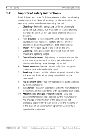
... spill liquid of power source indicated on the unit. 4. AR18-09-B003 | v1.1 | 2010.05 Installation and Operation Manual Bosch Security Systems Generally, using a dry cloth for future reference all servicing to qualified service personnel. 8. Installation - Any change or..., not expressly approved by Bosch, could void the warranty or, in accordance with the manufacturer's instructions and in the case of the following safety instructions. Heat Sources - Cleaning - Lightning - Attachments, changes or modifications - 8 en | Safety IP Camera 200 Series 1.2 Important safety...
... spill liquid of power source indicated on the unit. 4. AR18-09-B003 | v1.1 | 2010.05 Installation and Operation Manual Bosch Security Systems Generally, using a dry cloth for future reference all servicing to qualified service personnel. 8. Installation - Any change or..., not expressly approved by Bosch, could void the warranty or, in accordance with the manufacturer's instructions and in the case of the following safety instructions. Heat Sources - Cleaning - Lightning - Attachments, changes or modifications - 8 en | Safety IP Camera 200 Series 1.2 Important safety...

Operation Manual
Page 9
...004-000-00345-4. reorient or relocate the receiving antenna; - consult the dealer or an experienced radio/TV technician for corrective action. Bosch Security Systems Installation and Operation Manual AR18-09-B003 | v1.1 | 2010.05 increase the separation between the equipment and receiver;...receiver is available from that interference will not occur in a residential installation. The user may cause harmful interference to operate the equipment. IP Camera 200 Series Safety | en 9 1.3 FCC & ICES compliance FCC & ICES Information (U.S.A. If necessary, the user should consult the...
...004-000-00345-4. reorient or relocate the receiving antenna; - consult the dealer or an experienced radio/TV technician for corrective action. Bosch Security Systems Installation and Operation Manual AR18-09-B003 | v1.1 | 2010.05 increase the separation between the equipment and receiver;...receiver is available from that interference will not occur in a residential installation. The user may cause harmful interference to operate the equipment. IP Camera 200 Series Safety | en 9 1.3 FCC & ICES compliance FCC & ICES Information (U.S.A. If necessary, the user should consult the...

Operation Manual
Page 11
... Safety for disused electronic and electrical products. Your Bosch product was developed and manufactured with high-quality material and components that electronic and electrical appliances, which have reached the end of their working life, must be recycled and reused. Please dispose of this product. IP Camera 200 Series Safety | en 11 1.4 UL certification...
... Safety for disused electronic and electrical products. Your Bosch product was developed and manufactured with high-quality material and components that electronic and electrical appliances, which have reached the end of their working life, must be recycled and reused. Please dispose of this product. IP Camera 200 Series Safety | en 11 1.4 UL certification...
Operation Manual
Page 12
... in part on the work of the Independent JPEG Group. AR18-09-B003 | v1.1 | 2010.05 Installation and Operation Manual Bosch Security Systems Copyright 1988, 1994 Digital Equipment Corporation. 12 en | Safety IP Camera 200 Series 1.6 Copyrights The firmware 4.1 uses the fonts "Adobe-Helvetica-Bold-RNormal--24-240-75-75-P-138-ISO10646-1" and...
... in part on the work of the Independent JPEG Group. AR18-09-B003 | v1.1 | 2010.05 Installation and Operation Manual Bosch Security Systems Copyright 1988, 1994 Digital Equipment Corporation. 12 en | Safety IP Camera 200 Series 1.6 Copyrights The firmware 4.1 uses the fonts "Adobe-Helvetica-Bold-RNormal--24-240-75-75-P-138-ISO10646-1" and...

Operation Manual
Page 13
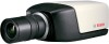
... storage inside a compact camera. IP Camera 200 Series 2 Introduction Introduction | en 13 2.1 Features This IP camera is a ready-to give clear images reducing bandwidth and storage.The camera can be used as a stand-alone video surveillance system with no additional equipment or it can easily integrate with the ONVIF standard for wide compatibility Bosch Security Systems Installation...
... storage inside a compact camera. IP Camera 200 Series 2 Introduction Introduction | en 13 2.1 Features This IP camera is a ready-to give clear images reducing bandwidth and storage.The camera can be used as a stand-alone video surveillance system with no additional equipment or it can easily integrate with the ONVIF standard for wide compatibility Bosch Security Systems Installation...
Operation Manual
Page 14
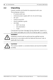
... the original packaging and notify the shipping agent or supplier. CD ROM - AR18-09-B003 | v1.1 | 2010.05 Installation and Operation Manual Bosch Security Systems Quick installation guide - IP camera with US, EU and UK plug - Tools If equipment has been damaged during shipment, repack it in accordance with care. CAUTION! SD card...
... the original packaging and notify the shipping agent or supplier. CD ROM - AR18-09-B003 | v1.1 | 2010.05 Installation and Operation Manual Bosch Security Systems Quick installation guide - IP camera with US, EU and UK plug - Tools If equipment has been damaged during shipment, repack it in accordance with care. CAUTION! SD card...
Operation Manual
Page 15
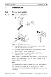
IP Camera 200 Series 3 Installation 3.1 3.1.1 Power connection DC power connection Installation | en 15 1 2 3 4 I/O Line-out DC12V Reset Ethernet Line-in the Installer Options menu.) Note: The date/time must be disabled in Figure 3.1 DC power connection 1. Insert the power connector jack from the power supply into the DC12V socket of the camera...power on the bottomfront of the camera. 3. When power is correct for recording. It is important to ensure that matches your outlet socket onto the supplied power supply. 2. Bosch Security Systems Installation and Operation Manual...
IP Camera 200 Series 3 Installation 3.1 3.1.1 Power connection DC power connection Installation | en 15 1 2 3 4 I/O Line-out DC12V Reset Ethernet Line-in the Installer Options menu.) Note: The date/time must be disabled in Figure 3.1 DC power connection 1. Insert the power connector jack from the power supply into the DC12V socket of the camera...power on the bottomfront of the camera. 3. When power is correct for recording. It is important to ensure that matches your outlet socket onto the supplied power supply. 2. Bosch Security Systems Installation and Operation Manual...

Operation Manual
Page 16
...the same time. Connect the camera to the camera via the Ethernet cable compliant with RJ45 connectors. - Power can accept power from both are connected and DC power removed, the camera will reboot and will continue working. Note: The camera can be powered by PoE.... AR18-09-B003 | v1.1 | 2010.05 Installation and Operation Manual Bosch Security Systems The primary source is the DC12V input. 16 en | Installation IP Camera 200 Series 3.2 Network (and power...
...the same time. Connect the camera to the camera via the Ethernet cable compliant with RJ45 connectors. - Power can accept power from both are connected and DC power removed, the camera will reboot and will continue working. Note: The camera can be powered by PoE.... AR18-09-B003 | v1.1 | 2010.05 Installation and Operation Manual Bosch Security Systems The primary source is the DC12V input. 16 en | Installation IP Camera 200 Series 3.2 Network (and power...

Operation Manual
Page 17
cut back 5 mm (0.2 in Negative - IP Camera 200 Series 3.3 I/O connector Installation | en 17 1 2 3 4 I/O Line-out DC12V Reset Ethernet Line-in I/O 5 mm (0.2 in) Figure 3.3 I/O connector pins Pin 1 Pin 4 Function Pin I/O socket Relay 1 Relay ... 4 Trigger in ) of insulation. - wire diameter AWG 22-28 for both stranded and solid; Max. 1 A continuous, 12 VA. - Trigger in: +9 VDC minimum; +30 VDC maximum. Bosch Security Systems Installation and Operation Manual AR18-09-B003 | v1.1 | 2010.05 Max. voltage 24 VAC or 24 VDC. Reverse polarity connection will be inactive...
cut back 5 mm (0.2 in Negative - IP Camera 200 Series 3.3 I/O connector Installation | en 17 1 2 3 4 I/O Line-out DC12V Reset Ethernet Line-in I/O 5 mm (0.2 in) Figure 3.3 I/O connector pins Pin 1 Pin 4 Function Pin I/O socket Relay 1 Relay ... 4 Trigger in ) of insulation. - wire diameter AWG 22-28 for both stranded and solid; Max. 1 A continuous, 12 VA. - Trigger in: +9 VDC minimum; +30 VDC maximum. Bosch Security Systems Installation and Operation Manual AR18-09-B003 | v1.1 | 2010.05 Max. voltage 24 VAC or 24 VDC. Reverse polarity connection will be inactive...

Operation Manual
Page 18
18 en | Installation 3.4 Audio connectors IP Camera 200 Series Line in Figure 3.5 Reset button AR18-09-B003 | v1.1 | 2010.05 Installation and Operation Manual Bosch Security Systems Resetting the camera If the camera cannot be connected because the IP address has changed, press and hold the reset button (7 seconds approximately) until the LED flashes (red) to the...
18 en | Installation 3.4 Audio connectors IP Camera 200 Series Line in Figure 3.5 Reset button AR18-09-B003 | v1.1 | 2010.05 Installation and Operation Manual Bosch Security Systems Resetting the camera If the camera cannot be connected because the IP address has changed, press and hold the reset button (7 seconds approximately) until the LED flashes (red) to the...

Operation Manual
Page 19
... www.boschsecurity.com Mounting the camera The camera can be mounted either from the top or from ground to prevent ground loops. CAUTION! Bosch Security Systems Installation and Operation Manual AR18-09-B003 | v1.1 | 2010.05 Slide the SD card into direct sunlight as this may damage the sensors. IP Camera 200 Series 3.6 SD card...
... www.boschsecurity.com Mounting the camera The camera can be mounted either from the top or from ground to prevent ground loops. CAUTION! Bosch Security Systems Installation and Operation Manual AR18-09-B003 | v1.1 | 2010.05 Slide the SD card into direct sunlight as this may damage the sensors. IP Camera 200 Series 3.6 SD card...

Operation Manual
Page 20
...-09-B003 | v1.1 | 2010.05 Installation and Operation Manual Bosch Security Systems Tighten the ball-socket adjustment ring (2) securely. Screw camera onto mount and, when in position, tighten the locking ring (1) securely. 5. 20 en | Installation IP Camera 200 Series 120° 120° 27 mm 3x Ø3.8... mm D: 26 mm 3x Ø6 mm D: 26 mm Figure 3.7 Mounting a camera 1. Use three screws to secure the base of the mounting unit to a ...
...-09-B003 | v1.1 | 2010.05 Installation and Operation Manual Bosch Security Systems Tighten the ball-socket adjustment ring (2) securely. Screw camera onto mount and, when in position, tighten the locking ring (1) securely. 5. 20 en | Installation IP Camera 200 Series 120° 120° 27 mm 3x Ø3.8... mm D: 26 mm 3x Ø6 mm D: 26 mm Figure 3.7 Mounting a camera 1. Use three screws to secure the base of the mounting unit to a ...

Operation Manual
Page 21
... root directory of the computer. Start the Web browser. 2. Enter the IP address of the unit. The default address pre-set from the IP address of the camera as the URL. IP Camera 200 Series Browser connection | en 21 4 Browser connection A computer with ...the product). 4.1 System requirements - If necessary, the required software and controls can be assigned a valid IP address to be set at least 1024 × 768 pixels, 16 or 32 bit color depth - Bosch...
... root directory of the computer. Start the Web browser. 2. Enter the IP address of the unit. The default address pre-set from the IP address of the camera as the URL. IP Camera 200 Series Browser connection | en 21 4 Browser connection A computer with ...the product). 4.1 System requirements - If necessary, the required software and controls can be assigned a valid IP address to be set at least 1024 × 768 pixels, 16 or 32 bit color depth - Bosch...

Operation Manual
Page 22
... established, the maximum number of limiting access across various authorization levels. 22 en | Browser connection IP Camera 200 Series Note: If the connection is used for a Radius network, connect it directly to 25 web browsers, or 50 VIDOS or Bosch VMS connections are supported. 4.2.1 Password protection in the appropriate fields. 2. To configure the...
... established, the maximum number of limiting access across various authorization levels. 22 en | Browser connection IP Camera 200 Series Note: If the connection is used for a Radius network, connect it directly to 25 web browsers, or 50 VIDOS or Bosch VMS connections are supported. 4.2.1 Password protection in the appropriate fields. 2. To configure the...


