Installation Instructions
Page 4
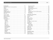
... | Installation Manual EN | ii Introduction 1-1 Digital video recorder for security applications 1-1 Versions 1-2 Features 1-2 On-screen help 1-3 Unpacking 1-3 Package contents 1-3 Installation environment 1-3 Associated equipment 1-4 DVD writer 1-4 Quick install 2-1 Primary connections 2-3 Optional connections 2-3 Powering up 2-3 First-time use 2-3 Quick install menu 2-4 Language 2-4 Time Zone 2-4 Time format 2-4 Time 2-4 Date format 2-4 Date 2-4 Active cams 2-4 Alarm Monitor 2-4 Recording settings 2-4 Network settings 2-4 Save & exit 2-4 Cancel 2-4 Recording...
... | Installation Manual EN | ii Introduction 1-1 Digital video recorder for security applications 1-1 Versions 1-2 Features 1-2 On-screen help 1-3 Unpacking 1-3 Package contents 1-3 Installation environment 1-3 Associated equipment 1-4 DVD writer 1-4 Quick install 2-1 Primary connections 2-3 Optional connections 2-3 Powering up 2-3 First-time use 2-3 Quick install menu 2-4 Language 2-4 Time Zone 2-4 Time format 2-4 Time 2-4 Date format 2-4 Date 2-4 Active cams 2-4 Alarm Monitor 2-4 Recording settings 2-4 Network settings 2-4 Save & exit 2-4 Cancel 2-4 Recording...
Installation Instructions
Page 5
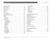
... Control port 4-6 External I/O connection 4-7 SCSI connection 4-8 Power Supply 4-9 Testing 4-9 Maintenance 4-9 Menu system 5-1 Overview of the menu system 5-2 Accessing the menu from the unit 5-2 Main Menu 5-3 History 5-4 History Filter 5-4 History List 5-4 Disk manager 5-4 Status Overview 5-4 Local archiving 5-5 Protected Recordings 5-5 Authenticity Check 5-6 Stop recording 5-6 Storage setup 5-6 Delete Video 5-6 Erase Disk 5-6 Time/Date 5-7 Synchronize 5-7 View Settings 5-7 Camera setup 5-7 Sequences 5-8 Configure Monitors 5-8 System Settings 5-9 Recording Setup...
... Control port 4-6 External I/O connection 4-7 SCSI connection 4-8 Power Supply 4-9 Testing 4-9 Maintenance 4-9 Menu system 5-1 Overview of the menu system 5-2 Accessing the menu from the unit 5-2 Main Menu 5-3 History 5-4 History Filter 5-4 History List 5-4 Disk manager 5-4 Status Overview 5-4 Local archiving 5-5 Protected Recordings 5-5 Authenticity Check 5-6 Stop recording 5-6 Storage setup 5-6 Delete Video 5-6 Erase Disk 5-6 Time/Date 5-7 Synchronize 5-7 View Settings 5-7 Camera setup 5-7 Sequences 5-8 Configure Monitors 5-8 System Settings 5-9 Recording Setup...

Installation Instructions
Page 9
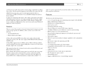
... can be easily operated and programmed via the front panel control keys and on any camera input. A dedicated PC player is a video recording system that can control multiple Divars. Alarm functions include motion detection in user-definable areas of the image on -screen display menu system. One monitor output provides fullscreen, quad and multiscreen viewing; Six simultaneous users can record multiple camera signals while simultaneously providing live viewing, playback and configuration. The Divar includes...
... can be easily operated and programmed via the front panel control keys and on any camera input. A dedicated PC player is a video recording system that can control multiple Divars. Alarm functions include motion detection in user-definable areas of the image on -screen display menu system. One monitor output provides fullscreen, quad and multiscreen viewing; Six simultaneous users can record multiple camera signals while simultaneously providing live viewing, playback and configuration. The Divar includes...
Installation Instructions
Page 10
... Bilinx supports the use of multiscreen views is connected to view live images or playback recordings from a Divar. Instructions that fewer cameras can be used to an ATM or POS device via an ATM/POS bridge unit and has a license installed. Bosch Security Systems In addition, a Divar can be frozen and zoomed. Looping auto-terminating video inputs, video outputs, alarm inputs and outputs, and remote control connectors are fewer camera keys and the number of Bilinx cameras. This manual...
... Bilinx supports the use of multiscreen views is connected to view live images or playback recordings from a Divar. Instructions that fewer cameras can be used to an ATM or POS device via an ATM/POS bridge unit and has a license installed. Bosch Security Systems In addition, a Divar can be frozen and zoomed. Looping auto-terminating video inputs, video outputs, alarm inputs and outputs, and remote control connectors are fewer camera keys and the number of Bilinx cameras. This manual...
Installation Instructions
Page 11
... items: • Digital Video Recorder (Divar 16, Divar 9 or Divar 6 unit) • Quick reference guide • Divar operation manual • Divar Control Center and Archive Player operation manual • Installation manual (this manual) • A 25-pin D-type connector board with screw terminals (used for switching and alarm connections) • A 15-pin D-type connector board with screw terminals (used for all packing materials for at least one second to the unit. Power Supply: Ensure that...
... items: • Digital Video Recorder (Divar 16, Divar 9 or Divar 6 unit) • Quick reference guide • Divar operation manual • Divar Control Center and Archive Player operation manual • Installation manual (this manual) • A 25-pin D-type connector board with screw terminals (used for switching and alarm connections) • A 15-pin D-type connector board with screw terminals (used for all packing materials for at least one second to the unit. Power Supply: Ensure that...
Installation Instructions
Page 12
... back on a PC. • To update the Archive Player software that appear on /off switch for security reasons.) • A keyboard (KBD-Digital). • PC for Control Center and Configuration Tool applications. • Pan/tilt/zoom control units. • Bosch D9000 series control panels. • SCSI cable for connection to external storage devices. • External storage devices (DVAD LP Storage Array or DVAS RAID Storage Array). • Video Manager for system expansion. •...
... back on a PC. • To update the Archive Player software that appear on /off switch for security reasons.) • A keyboard (KBD-Digital). • PC for Control Center and Configuration Tool applications. • Pan/tilt/zoom control units. • Bosch D9000 series control panels. • SCSI cable for connection to external storage devices. • External storage devices (DVAD LP Storage Array or DVAS RAID Storage Array). • Video Manager for system expansion. •...

Installation Instructions
Page 15
... B. 4. Connect monitor B to the BNC output MON A. Press the menu key . > The main menu appears full-screen on all connected equipment. 11. Select the Install item to switch off the menu. To open the Quick install menu at any other time: 1. Connect a pan/tilt/zoom control unit via the supplied 25-pin D-type connector board. 6. Connect up 10. Connect an external storage unit via the narrow 50-pin high density SCSI-2 port. (For Divars with a multiscreen display. First-time use...
... B. 4. Connect monitor B to the BNC output MON A. Press the menu key . > The main menu appears full-screen on all connected equipment. 11. Select the Install item to switch off the menu. To open the Quick install menu at any other time: 1. Connect a pan/tilt/zoom control unit via the supplied 25-pin D-type connector board. 6. Connect up 10. Connect an external storage unit via the narrow 50-pin high density SCSI-2 port. (For Divars with a multiscreen display. First-time use...
Installation Instructions
Page 18
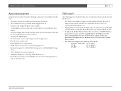
... every motion enabled camera is in motion recording 10% of the time. • During the night and weekend, one camera is in input alarm recording 1% of the time and in the IP, subnet mask and default gateway addresses when DHCP is set to No. >> MAC ADDRESS • The MAC address is an estimate of the recording duration based on the total amount of the time. >> NETWORK SETTINGS NETWORK SETTINGS DHCP DVR NAME IP ADDRESS SUBNET MASK DEFAULT GATEWAY MAC ADDRESS...
... every motion enabled camera is in motion recording 10% of the time. • During the night and weekend, one camera is in input alarm recording 1% of the time and in the IP, subnet mask and default gateway addresses when DHCP is set to No. >> MAC ADDRESS • The MAC address is an estimate of the recording duration based on the total amount of the time. >> NETWORK SETTINGS NETWORK SETTINGS DHCP DVR NAME IP ADDRESS SUBNET MASK DEFAULT GATEWAY MAC ADDRESS...

Installation Instructions
Page 21
... a camera signal. Network - flashes when an alarm is recording video. Symbols for controlling primary functions or alternate functions. lights to indicate that power is connected to various operating conditions. lights when the unit is detected. Bosch Security Systems Keys The keys on the front panel can be used for the primary functions are shown above the keys. Divar | Installation Manual | Operating instructions EN | 3-3 Indicators The power indicator unit. lights when a remote user is being supplied to...
... a camera signal. Network - flashes when an alarm is recording video. Symbols for controlling primary functions or alternate functions. lights to indicate that power is connected to various operating conditions. lights when the unit is detected. Bosch Security Systems Keys The keys on the front panel can be used for the primary functions are shown above the keys. Divar | Installation Manual | Operating instructions EN | 3-3 Indicators The power indicator unit. lights when a remote user is being supplied to...

Installation Instructions
Page 24
... | Installation Manual | Operating instructions EN | 3-6 Viewing pictures The unit has two monitor outputs, A and B. Monitor A Monitor A is not lit, press the ALT key and then press the monitor B key . Check that the light on monitor B. Viewing The drawing shows all possible views for monitor A. If is the main monitor. The Divar model and the number of full-screen pictures. Status messages, alarms, motion, and video loss warnings are sequenced on monitor A: 1. When the menu system...
... | Installation Manual | Operating instructions EN | 3-6 Viewing pictures The unit has two monitor outputs, A and B. Monitor A Monitor A is not lit, press the ALT key and then press the monitor B key . Check that the light on monitor B. Viewing The drawing shows all possible views for monitor A. If is the main monitor. The Divar model and the number of full-screen pictures. Status messages, alarms, motion, and video loss warnings are sequenced on monitor A: 1. When the menu system...
Installation Instructions
Page 34
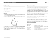
... front panel on each video input. Bosch Security Systems Camera connections Connect cameras to each camera. The Divar automatically configures itself as a PAL or NTSC unit. Cameras that includes: • left side of the first connected camera (lowest camera input number). Attach the mounting ears to the unit using the rack manufacturer's supplied hardware. Specification Input signal: Color standard: Gain control: Connector type: Composite video 1Vpp, 75 Ohm Embedded Bilinx command protocol (Divar Bilinx only).
... front panel on each video input. Bosch Security Systems Camera connections Connect cameras to each camera. The Divar automatically configures itself as a PAL or NTSC unit. Cameras that includes: • left side of the first connected camera (lowest camera input number). Attach the mounting ears to the unit using the rack manufacturer's supplied hardware. Specification Input signal: Color standard: Gain control: Connector type: Composite video 1Vpp, 75 Ohm Embedded Bilinx command protocol (Divar Bilinx only).
Installation Instructions
Page 35
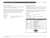
... RS232 clear to the unit. Divar | Installation Manual | Hardware setup EN | 4-3 Monitor connections Connect the unit to the monitors using the loopthrough output, then select the 75-ohm impedance setting on devices with BNC connectors. The Baud rate can be selected in the menu system. The serial RS232 console port connector is used to connect a PC to connect Bosch D9000 series control panels via an interface unit for configuration or service purposes. Specification Connector type: Maximum input...
... RS232 clear to the unit. Divar | Installation Manual | Hardware setup EN | 4-3 Monitor connections Connect the unit to the monitors using the loopthrough output, then select the 75-ohm impedance setting on devices with BNC connectors. The Baud rate can be selected in the menu system. The serial RS232 console port connector is used to connect a PC to connect Bosch D9000 series control panels via an interface unit for configuration or service purposes. Specification Connector type: Maximum input...
Installation Instructions
Page 37
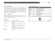
... plus No Connection No Connection Ethernet receive line minus No Connection No Connection 81 EN | 4-5 Panel view Bosch Security Systems Consult with the DHCP function switched on, so IP addresses are assigned automatically if the network server uses DHCP. (Refer to a network hub, use the supplied cross-over network cable. In-built compensation for the specific type of cable needed. To connect directly to the System settings/Connectivity/Network setup menu.) Specifications Connection: Differential signal voltage: Port details: Cable length: Impedance...
... plus No Connection No Connection Ethernet receive line minus No Connection No Connection 81 EN | 4-5 Panel view Bosch Security Systems Consult with the DHCP function switched on, so IP addresses are assigned automatically if the network server uses DHCP. (Refer to a network hub, use the supplied cross-over network cable. In-built compensation for the specific type of cable needed. To connect directly to the System settings/Connectivity/Network setup menu.) Specifications Connection: Differential signal voltage: Port details: Cable length: Impedance...

Installation Instructions
Page 44
... the dynamic characteristics of the unit. Unit behavior includes how events are set the actual reference time and date for the unit and the format that profile is used to tap the powerful functionality of working situations. Accessing the menu from the unit To open the menu: 1. Time/Date. System settings. Profiles are usually based on a calendar, switching on the monitors. It also defines recording rates both under normal...
... the dynamic characteristics of the unit. Unit behavior includes how events are set the actual reference time and date for the unit and the format that profile is used to tap the powerful functionality of working situations. Accessing the menu from the unit To open the menu: 1. Time/Date. System settings. Profiles are usually based on a calendar, switching on the monitors. It also defines recording rates both under normal...

Installation Instructions
Page 45
... MENUS NO Main menu History Disk manager Time / Date View settings System settings Profiles Advanced menus Bosch Security Systems * advanced items EN | 5-3 History View history list Disk manager Status overview Local archiving Protected recordings Authenticity check* Stop recording Storage setup* Delete video Erase disk Time / Date View settings Camera setup Sequences Configure monitors System settings Language Quick install Record setup Playback setup* Event setup History log setup Local passwords Connectivity* Licenses* Input and output contacts* Factory defaults Profiles Currently...
... MENUS NO Main menu History Disk manager Time / Date View settings System settings Profiles Advanced menus Bosch Security Systems * advanced items EN | 5-3 History View history list Disk manager Status overview Local archiving Protected recordings Authenticity check* Stop recording Storage setup* Delete video Erase disk Time / Date View settings Camera setup Sequences Configure monitors System settings Language Quick install Record setup Playback setup* Event setup History log setup Local passwords Connectivity* Licenses* Input and output contacts* Factory defaults Profiles Currently...

Installation Instructions
Page 50
... which cameras are displayed in full screen mode (Control Center version 1 only). • Use the arrow keys to select a position in the list. Select text intensity. Connected cameras are then listed in ascending order. >> CONFIGURE MONITORS • To view camera names, and time and date on the unit to enter a camera number in the list. • Press F2 to clear the rest of time each monitor. • Dwell time can be controlled remotely...
... which cameras are displayed in full screen mode (Control Center version 1 only). • Use the arrow keys to select a position in the list. Select text intensity. Connected cameras are then listed in ascending order. >> CONFIGURE MONITORS • To view camera names, and time and date on the unit to enter a camera number in the list. • Press F2 to clear the rest of time each monitor. • Dwell time can be controlled remotely...

Installation Instructions
Page 51
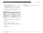
MAIN MENU SYSTEM SETTINGS LANGUAGE ENGLISH QUICK INSTALL > RECORDING SETUP > PLAYBACK SETUP > EVENT SETUP > HISTORY LOG SETUP > LOCAL PASSWORDS > CONNECTIVITY > LICENSES > INPUT AND OUTPUT CONTACTS > FACTORY DEFAULTS • Select the language for display of the ATM/POS data. • Press the current camera key during Live or Playback mode to switch the ATM/POS data display on monitor A in full-screen mode only. • Select position, duration, text intensity and font size for the menu from the...
MAIN MENU SYSTEM SETTINGS LANGUAGE ENGLISH QUICK INSTALL > RECORDING SETUP > PLAYBACK SETUP > EVENT SETUP > HISTORY LOG SETUP > LOCAL PASSWORDS > CONNECTIVITY > LICENSES > INPUT AND OUTPUT CONTACTS > FACTORY DEFAULTS • Select the language for display of the ATM/POS data. • Press the current camera key during Live or Playback mode to switch the ATM/POS data display on monitor A in full-screen mode only. • Select position, duration, text intensity and font size for the menu from the...

Installation Instructions
Page 54
... F2 to remove password protection. >> CONNECTIVITY The Connectivity menu gives access to settings that remote user. Bosch Security Systems The MAC address is read only. • If Discovery is set to Enabled, the Control Center can be set for up to six different users. • Restrict access to the unit by default. • Set Camera Control to allow access. • Enter the same begin and end addresses to specify an IP address range. • Use the up...
... F2 to remove password protection. >> CONNECTIVITY The Connectivity menu gives access to settings that remote user. Bosch Security Systems The MAC address is read only. • If Discovery is set to Enabled, the Control Center can be set for up to six different users. • Restrict access to the unit by default. • Set Camera Control to allow access. • Enter the same begin and end addresses to specify an IP address range. • Use the up...
Installation Instructions
Page 60
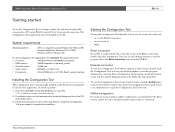
... desktop window to start the program. Divar | Installation Manual | Using the Configuration Tool EN | 6-2 Getting started To use the Configuration Tool to change settings, the unit must first be logged into the CD-ROM drive on the CD and double click it. 3. Follow the instructions on the task bar and the Programs menu item. The Configuration Tool application must be installed on how you install the Control Center...
... desktop window to start the program. Divar | Installation Manual | Using the Configuration Tool EN | 6-2 Getting started To use the Configuration Tool to change settings, the unit must first be logged into the CD-ROM drive on the CD and double click it. 3. Follow the instructions on the task bar and the Programs menu item. The Configuration Tool application must be installed on how you install the Control Center...
Installation Instructions
Page 71
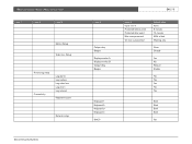
Divar | Installation Manual | Menu default values Level 1 Level 2 Level 3 Motion Setup Video loss Setup History log setup Connectivity Log alarms Log motions Log video loss Log errors Log network Keyboard access Network setup Bosch Security Systems Level 4 Output relay Beeper Display monitor A Display monitor B Output relay Beeper Keyboard 1 Keyboard 2 Keyboard 3 Keyboard 4 DHCP EN | 7-5 Level 5 Input 1 to 4 Protected before event Protected after event Max. auto-protected On max. auto-protect Default value None 5 minutes 10 minutes 25% of disk Warning only None Disable...
Divar | Installation Manual | Menu default values Level 1 Level 2 Level 3 Motion Setup Video loss Setup History log setup Connectivity Log alarms Log motions Log video loss Log errors Log network Keyboard access Network setup Bosch Security Systems Level 4 Output relay Beeper Display monitor A Display monitor B Output relay Beeper Keyboard 1 Keyboard 2 Keyboard 3 Keyboard 4 DHCP EN | 7-5 Level 5 Input 1 to 4 Protected before event Protected after event Max. auto-protected On max. auto-protect Default value None 5 minutes 10 minutes 25% of disk Warning only None Disable...


