

U8636 user's manual
Page 2
... 2. Layout of U8638 2-2. CPU Socket 478 Configuration Steps: 3-2. North Bridge Chipset Fan Header: JNFAN1 (Optional) 4. Jumpers, Headers & Connectors 4-1. CNR Code Primary/Secondary Selection: JCODECSEL 4-2. AUX Power Connector: JAUXPWR1(Optional) 4-6. Front Panel Connector: JPANEL1 4-3. Hard Disk Connectors: IDE1/IDE2 4-7. Notice Mainboard Features 1. Mainboard Configuration 2-1. Component Index 3. BIOS & Software 1-3. ATX 20-pin Power Connector: JATXPWR1 4-4. ATX 12V Power Connector: JATXPWR2 4-5. System Fan Header: JSFAN1 (Optional) 3-4. Floppy Disk Connector...
... 2. Layout of U8638 2-2. CPU Socket 478 Configuration Steps: 3-2. North Bridge Chipset Fan Header: JNFAN1 (Optional) 4. Jumpers, Headers & Connectors 4-1. CNR Code Primary/Secondary Selection: JCODECSEL 4-2. AUX Power Connector: JAUXPWR1(Optional) 4-6. Front Panel Connector: JPANEL1 4-3. Hard Disk Connectors: IDE1/IDE2 4-7. Notice Mainboard Features 1. Mainboard Configuration 2-1. Component Index 3. BIOS & Software 1-3. ATX 20-pin Power Connector: JATXPWR1 4-4. ATX 12V Power Connector: JATXPWR2 4-5. System Fan Header: JSFAN1 (Optional) 3-4. Floppy Disk Connector...

U8636 user's manual
Page 3
... Wake On LAN Header: JWOL1 4-11. Peripheral Port Features 6-1. Parallel Interface Port: JPRNT1 6-4. Audio Subsystem 6-6-1. CD-ROM Audio-In Header: JCDIN2(Optional) 6-6-3. Clear CMOS Jumper: JCMOS1 5. The Serial Interface: JCOM1 6-3-2. DIMM Module Configuration 6. USB Connectors 6-2-2. DIMM Features 5-2. 4-9. 5V/5VSB Selection for USB: JUSBV1 (Optional) 4-10. LAN Port Connector: (Optional) 6-3. Audio Port Connectors: JAUD_GAME 6-6. Front Panel Audio Header: JAUDIO1 6-6-4. Front USB Headers: JUSB2, JUSB3 4-12. PS/2 Mouse / Keyboard Connector: JKBMS1 6-2. USB & LAN Port...
... Wake On LAN Header: JWOL1 4-11. Peripheral Port Features 6-1. Parallel Interface Port: JPRNT1 6-4. Audio Subsystem 6-6-1. CD-ROM Audio-In Header: JCDIN2(Optional) 6-6-3. Clear CMOS Jumper: JCMOS1 5. The Serial Interface: JCOM1 6-3-2. DIMM Module Configuration 6. USB Connectors 6-2-2. DIMM Features 5-2. 4-9. 5V/5VSB Selection for USB: JUSBV1 (Optional) 4-10. LAN Port Connector: (Optional) 6-3. Audio Port Connectors: JAUD_GAME 6-6. Front Panel Audio Header: JAUDIO1 6-6-4. Front USB Headers: JUSB2, JUSB3 4-12. PS/2 Mouse / Keyboard Connector: JKBMS1 6-2. USB & LAN Port...
U8636 user's manual
Page 5
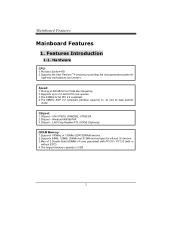
... without ECC). 4.The largest memory capacity is 2 GB. LAN Chip Realtek RTL 8100/B (Optional). 1.Supports 100MHz or 133MHz SDR SDRAM devices. 2.Supports 64Mb, 128Mb, 256Mb and 512Mb technologies for high-end workstations and servers. 1.Runing at 400 MHz Front Side Bus frequency. 2.Supports up to 2.0 GHz CPU core speeds. 3.The 33MHz 32 bit PCI 2.2 compliant. 4.The 66MHz AGP 2.0 compliant interface supports 1x, 2x and 4x data transfer mode. 1.Chipset - Mainboard Features 1.
... without ECC). 4.The largest memory capacity is 2 GB. LAN Chip Realtek RTL 8100/B (Optional). 1.Supports 100MHz or 133MHz SDR SDRAM devices. 2.Supports 64Mb, 128Mb, 256Mb and 512Mb technologies for high-end workstations and servers. 1.Runing at 400 MHz Front Side Bus frequency. 2.Supports up to 2.0 GHz CPU core speeds. 3.The 33MHz 32 bit PCI 2.2 compliant. 4.The 66MHz AGP 2.0 compliant interface supports 1x, 2x and 4x data transfer mode. 1.Chipset - Mainboard Features 1.
U8636 user's manual
Page 6
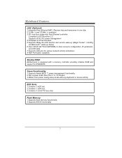
Motherboard is equipped with any keyboard or mouse activity. 1.Contains 1 AGP slot. 2.Contains 1 CNR slot. 3.Contains 3 32-bit PCI bus slots 1.Supports flash memory functionality. 2.Supports ESCD functionality. Compliant to PCI Revision 2.2 Supports ACPI, PCI power management 4.Compliant to PC99 standard. 5.Supports Wake-On-LAN function and remote wake-up (Magic Packet*, LinkChg and Microsoft ® wake-up frame) 6.Uses 93C46 (64*16-bit EEPROM) to store resource configuration, ID parameter, and VPD data. 7.Supports LED pins for ROM BIOS. 1.Supports Award BIOS ™...
Motherboard is equipped with any keyboard or mouse activity. 1.Contains 1 AGP slot. 2.Contains 1 CNR slot. 3.Contains 3 32-bit PCI bus slots 1.Supports flash memory functionality. 2.Supports ESCD functionality. Compliant to PCI Revision 2.2 Supports ACPI, PCI power management 4.Compliant to PC99 standard. 5.Supports Wake-On-LAN function and remote wake-up (Magic Packet*, LinkChg and Microsoft ® wake-up frame) 6.Uses 93C46 (64*16-bit EEPROM) to store resource configuration, ID parameter, and VPD data. 7.Supports LED pins for ROM BIOS. 1.Supports Award BIOS ™...
U8636 user's manual
Page 7
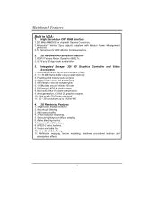
Full internal AGP 4x performance. 8. High quality DVD video playback. 11. 2D / 3D resolutions up to 1920x1440. 1. Specular lighting and diffuse shading. 6. MPEG-2 video textures. 9. Reflection mapping, texture morphing, shadows, procedural textures and atmospheric effects. Optimized Shared Memory Architecture (SMA). 2. 16 / 32 MB frame buffer using system memory. 3. Alpha blending modes. 7. ROP3 Ternary Raster Operation BitBLTs. 2. 8, 16 and 32 bpp mode acceleration...
Full internal AGP 4x performance. 8. High quality DVD video playback. 11. 2D / 3D resolutions up to 1920x1440. 1. Specular lighting and diffuse shading. 6. MPEG-2 video textures. 9. Reflection mapping, texture morphing, shadows, procedural textures and atmospheric effects. Optimized Shared Memory Architecture (SMA). 2. 16 / 32 MB frame buffer using system memory. 3. Alpha blending modes. 7. ROP3 Ternary Raster Operation BitBLTs. 2. 8, 16 and 32 bpp mode acceleration...
U8636 user's manual
Page 8
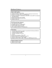
... 2.2 specification. 3.18-bit full duplex stereo ADC, DACs. 4.SNR>90 dB throughmixer and DAC. 5.AC-3 playback required for PVD applications. 1.One multi-mode Parallel Port capable of supporting the following specifications: Standard & Bidirection Parallel Port. Normal 2.Supports two serial ports, 16550 UART. 3.Supports Infrared Data Transmission using IrDA. 4.Supports PS/2 mouse and PS/2 keyboard. 5.Supports 360KB, 720KB, 1.2MB, 1.44MB, and 2.88MB floppy disk drives. 1.Monitors CPU Fan Speed. 2.Monitors System Voltage. Extended Capabilities Port (ECP...
... 2.2 specification. 3.18-bit full duplex stereo ADC, DACs. 4.SNR>90 dB throughmixer and DAC. 5.AC-3 playback required for PVD applications. 1.One multi-mode Parallel Port capable of supporting the following specifications: Standard & Bidirection Parallel Port. Normal 2.Supports two serial ports, 16550 UART. 3.Supports Infrared Data Transmission using IrDA. 4.Supports PS/2 mouse and PS/2 keyboard. 5.Supports 360KB, 720KB, 1.2MB, 1.44MB, and 2.88MB floppy disk drives. 1.Monitors CPU Fan Speed. 2.Monitors System Voltage. Extended Capabilities Port (ECP...

U8636 user's manual
Page 9
... Contents 1.HDD Cable. 2.FDD Cable. 3.Flash Memory Writer for BIOS Update. 4.USB2/USB3 Cable (Optional). 5.Rear I/O Panel for MS-DOS, Windows NT, Windows 2000, Windows 95/98, Windows ME, Windows XP, LINUX RedHat 7.2, and SCO UNIX etc. 1-3. 1.Supports two back panel Universal Serial Bus Ports and four front panel Universal Serial Bus Ports (optional). 2.Supports 48 MHz USB. 24.4cm x 24.4cm (WxL) 1-2. Offers the highest performance for micro ATX Case (Optional). 6.Fully Setup Driver CD. BIOS & Software 1.Phoenix legal BIOS. 2.Supports APM1.2. 3.Supports USB Function. 4.Supports ACPI.
... Contents 1.HDD Cable. 2.FDD Cable. 3.Flash Memory Writer for BIOS Update. 4.USB2/USB3 Cable (Optional). 5.Rear I/O Panel for MS-DOS, Windows NT, Windows 2000, Windows 95/98, Windows ME, Windows XP, LINUX RedHat 7.2, and SCO UNIX etc. 1-3. 1.Supports two back panel Universal Serial Bus Ports and four front panel Universal Serial Bus Ports (optional). 2.Supports 48 MHz USB. 24.4cm x 24.4cm (WxL) 1-2. Offers the highest performance for micro ATX Case (Optional). 6.Fully Setup Driver CD. BIOS & Software 1.Phoenix legal BIOS. 2.Supports APM1.2. 3.Supports USB Function. 4.Supports ACPI.

U8636 user's manual
Page 12
CPU Configuration 3-1. Press the lever down. CPU Socket 478 Configuration Steps: CPU Fan CPU 1. Pull the lever sideways away from the socket then raise the lever up to complete the installation. 3. Locate Pin A in the socket and look for the white dot or cut edge then insert the CPU. 3. Then Put the fan on the CPU and buckle it and put the fan's power port into the JCFAN1, then to a 90-degree angle. 2. Match Pin A with the white dot/cut edge in the CPU.
CPU Configuration 3-1. Press the lever down. CPU Socket 478 Configuration Steps: CPU Fan CPU 1. Pull the lever sideways away from the socket then raise the lever up to complete the installation. 3. Locate Pin A in the socket and look for the white dot or cut edge then insert the CPU. 3. Then Put the fan on the CPU and buckle it and put the fan's power port into the JCFAN1, then to a 90-degree angle. 2. Match Pin A with the white dot/cut edge in the CPU.

U8636 user's manual
Page 15
CNR Code Primary/Secondary Selection: JCODECSEL Pin No. 1-2 2-3 Assignment On-board Primary Codec CNR Primary Codec Jumpers, Headers & Connectors 4-1. 4.
CNR Code Primary/Secondary Selection: JCODECSEL Pin No. 1-2 2-3 Assignment On-board Primary Codec CNR Primary Codec Jumpers, Headers & Connectors 4-1. 4.

U8636 user's manual
Page 16
... front panel connector. The speaker (onboard or offboard) provides error beep code information during the Power On Self-Test when the computer cannot use the video interface. 4-2. RST (Reset Button) This connector can be connected to reset and run the POST (Power On Self Test). Front Panel Connector: JPANEL1 Pin Assignment Function Pin Assignment Function No. This switch is not connected to a momentary SPST switch. An offboard speaker can be installed on 15 Reset Control Button 16 Ground Button 17...
... front panel connector. The speaker (onboard or offboard) provides error beep code information during the Power On Self-Test when the computer cannot use the video interface. 4-2. RST (Reset Button) This connector can be connected to reset and run the POST (Power On Self Test). Front Panel Connector: JPANEL1 Pin Assignment Function Pin Assignment Function No. This switch is not connected to a momentary SPST switch. An offboard speaker can be installed on 15 Reset Control Button 16 Ground Button 17...

U8636 user's manual
Page 17
... the system board). The switch must pass before the power supply will power down the monitor and the hard disk when not in the system BIOS and the APM driver must be attached to a front panel power switch. ON/OFF (Power Button) This connector can be loaded. This disk activity only applies to those IDE drives directly attached to an infrared sensing device. To configure this option, you need to connect a button from portable devices such...
... the system board). The switch must pass before the power supply will power down the monitor and the hard disk when not in the system BIOS and the APM driver must be attached to a front panel power switch. ON/OFF (Power Button) This connector can be loaded. This disk activity only applies to those IDE drives directly attached to an infrared sensing device. To configure this option, you need to connect a button from portable devices such...

U8636 user's manual
Page 19
... two HDD connectors IDE1 (primary) and IDE2 (secondary). • IDE1 (Primary IDE Connector) The first hard drive should always be set to IDE1. The configuration is similar to Slave mode by setting the jumper accordingly. • IDE2 (Secondary IDE Connector) The IDE2 controller can connect a Master and a Slave drive. Hard Disk Connectors: IDE1/IDE2 This mainboard has a 32-bit Enhanced PCI IDE Controller that supports 360K, 720K, 1.2M, 1.44M and 2.88M floppy disk types. This connector supports the provided floppy drive ribbon cables...
... two HDD connectors IDE1 (primary) and IDE2 (secondary). • IDE1 (Primary IDE Connector) The first hard drive should always be set to IDE1. The configuration is similar to Slave mode by setting the jumper accordingly. • IDE2 (Secondary IDE Connector) The IDE2 controller can connect a Master and a Slave drive. Hard Disk Connectors: IDE1/IDE2 This mainboard has a 32-bit Enhanced PCI IDE Controller that supports 360K, 720K, 1.2M, 1.44M and 2.88M floppy disk types. This connector supports the provided floppy drive ribbon cables...

U8636 user's manual
Page 20
Front USB Headers: JUSB2, JUSB3 (JUSB2) Pin Assignment Pin Assignment 1 +5V(fused) 2 +5V(fused) 3 USBP2- 4 USBP3- 5 USBP2+ 6 USBP3+ 7 Ground 8 Ground 9 KEY 10 NC (JUSB3) Pin Assignment Pin Assignment 1 +5V(fused) 2 +5V(fused) 3 USBP4- 4 USBP5- 5 USBP4+ 6 USBP5+ 7 Ground 8 Ground 9 KEY 10 NC Wake On LAN Header: JWOL1 Pin No. 1 2 3 Assignment 5V SB Ground Wake up 4-11. 4-9. 5V/5VSB Selection for USB: JUSBV1 (Optional) JUSBV1 1 3 1-2 Closed 1 3 2-3 Closed Assignment 5V 5V SB 4-10.
Front USB Headers: JUSB2, JUSB3 (JUSB2) Pin Assignment Pin Assignment 1 +5V(fused) 2 +5V(fused) 3 USBP2- 4 USBP3- 5 USBP2+ 6 USBP3+ 7 Ground 8 Ground 9 KEY 10 NC (JUSB3) Pin Assignment Pin Assignment 1 +5V(fused) 2 +5V(fused) 3 USBP4- 4 USBP5- 5 USBP4+ 6 USBP5+ 7 Ground 8 Ground 9 KEY 10 NC Wake On LAN Header: JWOL1 Pin No. 1 2 3 Assignment 5V SB Ground Wake up 4-11. 4-9. 5V/5VSB Selection for USB: JUSBV1 (Optional) JUSBV1 1 3 1-2 Closed 1 3 2-3 Closed Assignment 5V 5V SB 4-10.

U8636 user's manual
Page 22
5. ECC (Memory error correcting code) DRAM Type: 3.3V SDRAM PC100/ PC133 Type required. 64MB/128MB/256MB/512MB DIMM Module (168 pin) Total Memory size (MB) DIMM 1 DIMM 2 64M 64M 128M 192M 320M 576M 128M 128M 192M 256M 384M 640M 256M 256M 320M 384M 512M 768M 512M 512M 576M 640M ... M 512 M -- -64 M 64 M 128 M 256 M 512 M -- -128 M 64 M 128 M 256 M 512 M -- -256 M 64 M 128 M 256 M 512 M -- -512 M 64 M 128 M 256 M 512 M DIMM Features When you use the on board VGA function, the DIMM ECC function will be disabled. RAM Module Configuration 5-1.
5. ECC (Memory error correcting code) DRAM Type: 3.3V SDRAM PC100/ PC133 Type required. 64MB/128MB/256MB/512MB DIMM Module (168 pin) Total Memory size (MB) DIMM 1 DIMM 2 64M 64M 128M 192M 320M 576M 128M 128M 192M 256M 384M 640M 256M 256M 320M 384M 512M 768M 512M 512M 576M 640M ... M 512 M -- -64 M 64 M 128 M 256 M 512 M -- -128 M 64 M 128 M 256 M 512 M -- -256 M 64 M 128 M 256 M 512 M -- -512 M 64 M 128 M 256 M 512 M DIMM Features When you use the on board VGA function, the DIMM ECC function will be disabled. RAM Module Configuration 5-1.

U8636 user's manual
Page 24
6. PS/2 Mouse / Keyboard Connector: JKBMS1 The motherboard provides a standard PS/2 mouse / Keyboard mini DIN connector for attaching a PS/2 mouse. The connector location and pin definition are shown below: PS/2 Mouse / Keyboard Connectors Pin 1 2 3 4 5 6 Assignment Data No connect Ground +5 V (fused) Clock No connect You can plug a PS/2 mouse / Keyboard directly into this connector. Peripheral Port Features JKBMS1 PS/2 JUSBLAN1 Mouse LAN JPRNT1 Parallel JAUD_GAME Game Port PS/2 Keyboard USB COM1 JCOM1 VGA1 Speaker Out Line In Mic In JVGA1 6-1.
6. PS/2 Mouse / Keyboard Connector: JKBMS1 The motherboard provides a standard PS/2 mouse / Keyboard mini DIN connector for attaching a PS/2 mouse. The connector location and pin definition are shown below: PS/2 Mouse / Keyboard Connectors Pin 1 2 3 4 5 6 Assignment Data No connect Ground +5 V (fused) Clock No connect You can plug a PS/2 mouse / Keyboard directly into this connector. Peripheral Port Features JKBMS1 PS/2 JUSBLAN1 Mouse LAN JPRNT1 Parallel JAUD_GAME Game Port PS/2 Keyboard USB COM1 JCOM1 VGA1 Speaker Out Line In Mic In JVGA1 6-1.

U8636 user's manual
Page 26
LAN Port Connector Pin 9 10 11 12 13 14 15 16 Assignment TD+ TDRD+ NC NC RDNC NC You can set up the connection by entering account information provided by your ISP. 6-2-2. LAN Port Connector: (Optional) This connector allows you to connect to the Internet through a Local Area Network (LAN).
LAN Port Connector Pin 9 10 11 12 13 14 15 16 Assignment TD+ TDRD+ NC NC RDNC NC You can set up the connection by entering account information provided by your ISP. 6-2-2. LAN Port Connector: (Optional) This connector allows you to connect to the Internet through a Local Area Network (LAN).
U8636 user's manual
Page 27
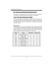
... the 9-pin connector and some of interface ports will be explained in many ways, and it may be used when configuring certain software programs to connect your computer with the serial ports. Mice, printers, modems and other peripheral devices can be connected to become familiar with one serial port and one parallel port. This information can be used in this chapter. 6-3-1. Both types of the 25-pin connector.
... the 9-pin connector and some of interface ports will be explained in many ways, and it may be used when configuring certain software programs to connect your computer with the serial ports. Mice, printers, modems and other peripheral devices can be connected to become familiar with one serial port and one parallel port. This information can be used in this chapter. 6-3-1. Both types of the 25-pin connector.

U8636 BIOS setup guide
Page 1
BIOS Setup Main Menu Standard CMOS Features Advanced BIOS Features Advanced Chipset Features Integrated Peripherals Power Management Setup PnP/PCI Configurations PC Health Status Frequency/Voltage Control
BIOS Setup Main Menu Standard CMOS Features Advanced BIOS Features Advanced Chipset Features Integrated Peripherals Power Management Setup PnP/PCI Configurations PC Health Status Frequency/Voltage Control

U8636 BIOS setup guide
Page 3
... the numeric value or make changes Decrease the numeric value or make changes Increase the numeric value or make changes Decrease the numeric value or make changes General help on Setup navigation keys Load previous values from CMOS Load the optimized defaults Save all the CMOS changes and exit Keystroke Up arrow Down arrow Left arrow Right arrow Esc Move Enter PgUp key PgDn key + Key -
... the numeric value or make changes Decrease the numeric value or make changes Increase the numeric value or make changes Decrease the numeric value or make changes General help on Setup navigation keys Load previous values from CMOS Load the optimized defaults Save all the CMOS changes and exit Keystroke Up arrow Down arrow Left arrow Right arrow Esc Move Enter PgUp key PgDn key + Key -
U8636 BIOS setup guide
Page 8
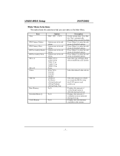
... changes when you . Date Item Options MM DD YYYY IDE Primary Master IDE Primary Slave IDE Secondary Master IDE Secondary Slave Drive A Drive B Video Halt On Base Memory Options are in its sub menu. Press to enter the sub menu of detailed options Press to stop the POST process and notify you set the date. Displays the amount of detailed options. Options are in the system. Select the default video device. Displays the total memory...
... changes when you . Date Item Options MM DD YYYY IDE Primary Master IDE Primary Slave IDE Secondary Master IDE Secondary Slave Drive A Drive B Video Halt On Base Memory Options are in its sub menu. Press to enter the sub menu of detailed options Press to stop the POST process and notify you set the date. Displays the amount of detailed options. Options are in the system. Select the default video device. Displays the total memory...


