Setup Manual
Page 2
Table of Contents Chapter 1: Introduction 1 1.1 Before You Start 1 1.2 Package Checklist 1 1.3 Motherboard Features 2 1.4 Rear Panel Connectors 3 1.5 Motherboard Layout (TP45 HP 4 1.6 Motherboard Layout (TP43 HP 5 Chapter 2: Hardware Installation 6 2.1 Installing Central Processing Unit (CPU 6 2.2 FAN Headers 8 2.3 Installing System Memory 9 2.4 Connectors and Slots 11 Chapter 3: Headers & Jumpers Setup 14 3.1 ...
Table of Contents Chapter 1: Introduction 1 1.1 Before You Start 1 1.2 Package Checklist 1 1.3 Motherboard Features 2 1.4 Rear Panel Connectors 3 1.5 Motherboard Layout (TP45 HP 4 1.6 Motherboard Layout (TP43 HP 5 Chapter 2: Hardware Installation 6 2.1 Installing Central Processing Unit (CPU 6 2.2 FAN Headers 8 2.3 Installing System Memory 9 2.4 Connectors and Slots 11 Chapter 3: Headers & Jumpers Setup 14 3.1 ...
Setup Manual
Page 3
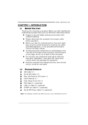
...the case after installation. CHAPTER 1: INTRODUCTION TP45 HP/TP43 HP 1.1 BEFORE YOU START Thank you take the motherboard out from anti-static bag, ground yourself properly by area or your motherboard version. 1 Hold the board on the edge, do not try to bend or flex the board. „..., or use grounded wrist strap to remove the static charge. „ Avoid touching the components on motherboard or the rear side of the board unless necessary. Before you start installing the motherboard, please make sure you follow the instructions below: „ Prepare a dry and stable working environment...
...the case after installation. CHAPTER 1: INTRODUCTION TP45 HP/TP43 HP 1.1 BEFORE YOU START Thank you take the motherboard out from anti-static bag, ground yourself properly by area or your motherboard version. 1 Hold the board on the edge, do not try to bend or flex the board. „..., or use grounded wrist strap to remove the static charge. „ Avoid touching the components on motherboard or the rear side of the board unless necessary. Before you start installing the motherboard, please make sure you follow the instructions below: „ Prepare a dry and stable working environment...
Setup Manual
Page 6
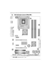
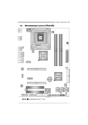
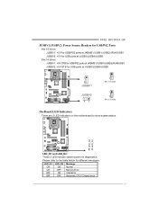
SATA2 RS TSW1 PWRSW1 4 Motherboard Manual 1.5 MOTHERBOARD LAYOUT (TP45 HP) JKBMS1 JATXPWR1 JUSB2 LGA775 CPU1 JCFAN1 DDR 2_A 1 DDR 2_A 2 DDR 2_B 1 DDR 2_B 2 BIOS JUSBV1 JUSB1 JRJ45USB1 JNFAN1 JAUDIO1 J1 Int el P45 JATXPWR2 LAN JCDIN1 PEX1_2 PEX16_1 JPE1 JPE3 JPE5 JPE7 PEX1_1 JPE2 JPE4 JPE6 JPE8 JPE9 BAT1 I ntel ICH10 JCMO S1 IDE1 CODEC PEX16_2 PCI1 SATA5 IDE SATA3 SATA1 JSPDIF_OUT1 PCI2 JAUDIOF1 JCOM1 JPRNT1 FDD1 Super I/O SATA6 SATA4 JUSBV2 JSFAN1 JUSB5 JUSB4 JUSB3 JPANEL1 LED_D2 LED_D1 Note: ■ represents the 1st pin.
SATA2 RS TSW1 PWRSW1 4 Motherboard Manual 1.5 MOTHERBOARD LAYOUT (TP45 HP) JKBMS1 JATXPWR1 JUSB2 LGA775 CPU1 JCFAN1 DDR 2_A 1 DDR 2_A 2 DDR 2_B 1 DDR 2_B 2 BIOS JUSBV1 JUSB1 JRJ45USB1 JNFAN1 JAUDIO1 J1 Int el P45 JATXPWR2 LAN JCDIN1 PEX1_2 PEX16_1 JPE1 JPE3 JPE5 JPE7 PEX1_1 JPE2 JPE4 JPE6 JPE8 JPE9 BAT1 I ntel ICH10 JCMO S1 IDE1 CODEC PEX16_2 PCI1 SATA5 IDE SATA3 SATA1 JSPDIF_OUT1 PCI2 JAUDIOF1 JCOM1 JPRNT1 FDD1 Super I/O SATA6 SATA4 JUSBV2 JSFAN1 JUSB5 JUSB4 JUSB3 JPANEL1 LED_D2 LED_D1 Note: ■ represents the 1st pin.
Setup Manual
Page 7
TP45 HP/TP43 HP 1.6 MOTHERBOARD LAYOUT (TP43 HP) JKBMS1 JATXPWR1 JUSB2 LGA775 CPU1 JCFAN1 DDR 2_A 1 DDR 2_A 2 DDR 2_B 1 DDR 2_B 2 BIOS JUSBV1 JUSB1 JRJ45USB1 JNFAN1 JAUDIO1 J1 Int el P43 JATXPWR2 LAN PEX16_1 JCMO S1 JCDIN1 PEX1_1 I ntel IDE1 ICH10 BAT1 CODEC PEX16_2 PCI1 SATA5 IDE SATA3 SATA1 JSPDIF_OUT1 PCI2 JAUDIOF1 JCOM1 JPRNT1 FDD1 Super I/O SATA6 SATA4 JUSBV2 JSFAN1 JUSB5 JUSB4 JUSB3 JPANEL1 LED_D2 LED_D1 Note: ■ represents the 1st pin. SATA2 RS TSW1 PWRSW1 5
TP45 HP/TP43 HP 1.6 MOTHERBOARD LAYOUT (TP43 HP) JKBMS1 JATXPWR1 JUSB2 LGA775 CPU1 JCFAN1 DDR 2_A 1 DDR 2_A 2 DDR 2_B 1 DDR 2_B 2 BIOS JUSBV1 JUSB1 JRJ45USB1 JNFAN1 JAUDIO1 J1 Int el P43 JATXPWR2 LAN PEX16_1 JCMO S1 JCDIN1 PEX1_1 I ntel IDE1 ICH10 BAT1 CODEC PEX16_2 PCI1 SATA5 IDE SATA3 SATA1 JSPDIF_OUT1 PCI2 JAUDIOF1 JCOM1 JPRNT1 FDD1 Super I/O SATA6 SATA4 JUSBV2 JSFAN1 JUSB5 JUSB4 JUSB3 JPANEL1 LED_D2 LED_D1 Note: ■ represents the 1st pin. SATA2 RS TSW1 PWRSW1 5
Setup Manual
Page 8
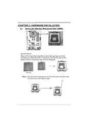
When the CPU is removed, cover the Pin Cap on the empty socket to a 90-degree angle. 6 Motherboard Manual CHAPTER 2: HARDWARE INSTALLATION 2.1 INSTALLING CENTRAL PROCESSING UNIT (CPU) Special Notice: Remove Pin Cap before installation, and make good preservation for future use. Pin Cap Step 1: Pull the socket locking lever out from the socket and then raise the lever up to ensure pin legs won't be damaged.
When the CPU is removed, cover the Pin Cap on the empty socket to a 90-degree angle. 6 Motherboard Manual CHAPTER 2: HARDWARE INSTALLATION 2.1 INSTALLING CENTRAL PROCESSING UNIT (CPU) Special Notice: Remove Pin Cap before installation, and make good preservation for future use. Pin Cap Step 1: Pull the socket locking lever out from the socket and then raise the lever up to ensure pin legs won't be damaged.

Setup Manual
Page 10
... wire is the positive and should be connected to pin#2, and the black wire is Ground and should be different according to the fan manufacturer. Motherboard Manual 2.2 FAN HEADERS These fan headers support cooling-fans built in the computer. JCFAN1: CPU Fan Header Pin Assignment 4 1 1 Ground 2 +12V 3 FAN RPM rate sense...
... wire is the positive and should be connected to pin#2, and the black wire is Ground and should be different according to the fan manufacturer. Motherboard Manual 2.2 FAN HEADERS These fan headers support cooling-fans built in the computer. JCFAN1: CPU Fan Header Pin Assignment 4 1 1 Ground 2 +12V 3 FAN RPM rate sense...
Setup Manual
Page 12
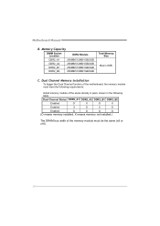
Dual Channel Memory installation To trigger the Dual Channel function of the motherboard, the memory module must meet the following requirements: Install memory module of the memory module must be the same (x8 or x16) 10...X O X Enabled X O X O Enabled O O O O (O means memory installed, X means memory not installed.) The DRAM bus width of the same density in pairs, shown in the following table. Motherboard Manual B. Memory Capacity DIMM Socket Location DDR2 Module DDR2_A1 256MB/512MB/1GB/2GB DDR2_A2 256MB/512MB/1GB/2GB DDR2_B1 256MB/512MB/1GB/2GB DDR2_B2 256MB...
Dual Channel Memory installation To trigger the Dual Channel function of the motherboard, the memory module must meet the following requirements: Install memory module of the memory module must be the same (x8 or x16) 10...X O X Enabled X O X O Enabled O O O O (O means memory installed, X means memory not installed.) The DRAM bus width of the same density in pairs, shown in the following table. Motherboard Manual B. Memory Capacity DIMM Socket Location DDR2 Module DDR2_A1 256MB/512MB/1GB/2GB DDR2_A2 256MB/512MB/1GB/2GB DDR2_B1 256MB/512MB/1GB/2GB DDR2_B2 256MB...
Setup Manual
Page 13
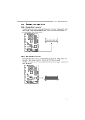
TP45 HP/TP43 HP 2.4 CONNECTORS AND SLOTS FDD1: Floppy Disk Connector The motherboard provides a standard floppy disk connector that provides PIO Mode 0~4, Bus Master, and Ultra DMA 33/66/100/133 functionality. The IDE connector can connect a master and a slave drive, so you can connect up to two drives. 39 1 40 2 11 This connector supports the provided floppy drive ribbon cables. 33 1 34 2 IDE1: IDE/ATAPI Connector The motherboard has a 32-bit Enhanced PCI IDE Controller that supports 360K, 720K, 1.2M, 1.44M and 2.88M floppy disk types.
TP45 HP/TP43 HP 2.4 CONNECTORS AND SLOTS FDD1: Floppy Disk Connector The motherboard provides a standard floppy disk connector that provides PIO Mode 0~4, Bus Master, and Ultra DMA 33/66/100/133 functionality. The IDE connector can connect a master and a slave drive, so you can connect up to two drives. 39 1 40 2 11 This connector supports the provided floppy drive ribbon cables. 33 1 34 2 IDE1: IDE/ATAPI Connector The motherboard has a 32-bit Enhanced PCI IDE Controller that supports 360K, 720K, 1.2M, 1.44M and 2.88M floppy disk types.
Setup Manual
Page 14
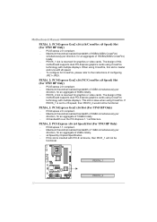
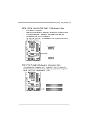
...) totally. - x4 Speed by Chipset Specification. - The design of 8GB/s totally. - To configure for an aggregate of this motherboard supports dual PCI-Express graphics cards using CrossFire technology with multiple displays. Maximum theoretical realized bandwidth of 16GB/s totally. - 2X bandwidth... over the PCI-Express 1.1 architecture. PEX16_1 PEX16_2 12 PEX16_1 slot is set to the instructions of this motherboard supports dual PCI-Express graphics cards using CrossFire technology with multiple displays. PEX16_1: PCI-Express Gen2 x16 Slot (For TP43 HP ...
...) totally. - x4 Speed by Chipset Specification. - The design of 8GB/s totally. - To configure for an aggregate of this motherboard supports dual PCI-Express graphics cards using CrossFire technology with multiple displays. Maximum theoretical realized bandwidth of 16GB/s totally. - 2X bandwidth... over the PCI-Express 1.1 architecture. PEX16_1 PEX16_2 12 PEX16_1 slot is set to the instructions of this motherboard supports dual PCI-Express graphics cards using CrossFire technology with multiple displays. PEX16_1: PCI-Express Gen2 x16 Slot (For TP43 HP ...
Setup Manual
Page 15
... is equipped with PCI-E x4 device, then PEX1_1 will not be functional. (For TP45 HP Only) PEX1_2 PEX1_1 PCI1~PCI2: Peripheral Component Interconnect Slots This motherboard is designated as 32 bits. PCI-Express 1.1 compliant. - Data transfer bandwidth up to 250MB/s per direction; 500MB/s in total. - PCI-Express supports a raw bit-rate...
... is equipped with PCI-E x4 device, then PEX1_1 will not be functional. (For TP45 HP Only) PEX1_2 PEX1_1 PCI1~PCI2: Peripheral Component Interconnect Slots This motherboard is designated as 32 bits. PCI-Express 1.1 compliant. - Data transfer bandwidth up to 250MB/s per direction; 500MB/s in total. - PCI-Express supports a raw bit-rate...

Setup Manual
Page 16
... 15 16 Assignment N/A N/A N/A Power LED (+) Power LED (+) Power LED (-) Power button Ground Function N/A N/A Power LED Power-on , Reset, HDD LED, Power LED, and speaker connection. Motherboard Manual CHAPTER 3: HEADERS & JUMPERS SETUP 3.1 HOW TO SETUP JUMPERS The illustration shows how to connect the PC case's front panel switch functions. When the jumper...
... 15 16 Assignment N/A N/A N/A Power LED (+) Power LED (+) Power LED (-) Power button Ground Function N/A N/A Power LED Power-on , Reset, HDD LED, Power LED, and speaker connection. Motherboard Manual CHAPTER 3: HEADERS & JUMPERS SETUP 3.1 HOW TO SETUP JUMPERS The illustration shows how to connect the PC case's front panel switch functions. When the jumper...
Setup Manual
Page 18
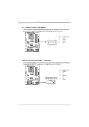
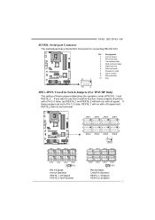
SATA5 SATA3 SATA1 SATA6 SATA4 SATA2 Pin Assignment 1 Ground 2 TX+ 3 TX4 Ground 5 RX6 RX+ 7 Ground 741 16 Exclusive power for graphics cards. Pin Assignment 1 +12V 1 4 2 Ground 3 Ground 4 VCC SATA1~SATA6: Serial ATA Connectors The motherboard has a PCI to SATA Controller with 6 channels SATA interface, it satisfies the SATA 2.0 spec and with transfer rate of 3.0Gb/s. Motherboard Manual J1: Auxiliary Power for Graphics This connector is an auxiliary power connection for the graphics card provides better graphics performance.
SATA5 SATA3 SATA1 SATA6 SATA4 SATA2 Pin Assignment 1 Ground 2 TX+ 3 TX4 Ground 5 RX6 RX+ 7 Ground 741 16 Exclusive power for graphics cards. Pin Assignment 1 +12V 1 4 2 Ground 3 Ground 4 VCC SATA1~SATA6: Serial ATA Connectors The motherboard has a PCI to SATA Controller with 6 channels SATA interface, it satisfies the SATA 2.0 spec and with transfer rate of 3.0Gb/s. Motherboard Manual J1: Auxiliary Power for Graphics This connector is an auxiliary power connection for the graphics card provides better graphics performance.
Setup Manual
Page 20
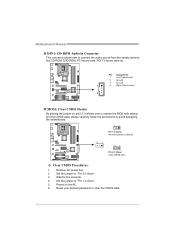
... or clear the CMOS data. 18 Set the jumper to "Pin 2-3 close ". 5. Set the jumper to "Pin 1-2 close ". 3. Motherboard Manual JCDIN1: CD-ROM Audio-in Connector This connector allows user to avoid damaging the motherboard. 3 1 Pin 1-2 Close: Normal Operation (default). 3 1 3 1 Pin 2-3 Close: Clear CMOS data. ※ Clear CMOS Procedures: 1. Remove AC power...
... or clear the CMOS data. 18 Set the jumper to "Pin 2-3 close ". 5. Set the jumper to "Pin 1-2 close ". 3. Motherboard Manual JCDIN1: CD-ROM Audio-in Connector This connector allows user to avoid damaging the motherboard. 3 1 Pin 1-2 Close: Normal Operation (default). 3 1 3 1 Pin 2-3 Close: Clear CMOS data. ※ Clear CMOS Procedures: 1. Remove AC power...
Setup Manual
Page 21
JUSBV2: +5V for USB ports at JKBMS1/JUSB1/JUSB2/JRJ45USB1. LED_D2 LED_D1 LED_D1 and LED_D2: These 2 LED indicate system power on the motherboard to the table below for USB ports at JKBMS1/JUSB1/JUSB2/JRJ45USB1. TP45 HP/TP43 HP JUSBV1/JUSBV2: Power Source Headers for USB/PS2 Ports ...
JUSBV2: +5V for USB ports at JKBMS1/JUSB1/JUSB2/JRJ45USB1. LED_D2 LED_D1 LED_D1 and LED_D2: These 2 LED indicate system power on the motherboard to the table below for USB ports at JKBMS1/JUSB1/JUSB2/JRJ45USB1. TP45 HP/TP43 HP JUSBV1/JUSBV2: Power Source Headers for USB/PS2 Ports ...
Setup Manual
Page 22
RSTSW1: This is an on -board Reset button. Motherboard Manual On-Board Buttons There are 2 on the PC. 25 1 Pin Assignment 1 -Strobe 2 -ALF 3 Data 0 4 -Error 5 Data 1 6 -Init 7 Data 2 8 -Scltin 9 Data 3 10 Ground 11 Data 4 ...
RSTSW1: This is an on -board Reset button. Motherboard Manual On-Board Buttons There are 2 on the PC. 25 1 Pin Assignment 1 -Strobe 2 -ALF 3 Data 0 4 -Error 5 Data 1 6 -Init 7 Data 2 8 -Scltin 9 Data 3 10 Ground 11 Data 4 ...
Setup Manual
Page 23
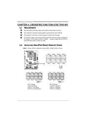
... 1 Carrier detect 2 Received data 3 Transmitted data 4 Data terminal ready 5 Signal ground 6 Data set to Pin 1-2 close ; TP45 HP/TP43 HP JCOM1: Serial port Connector The motherboard has a Serial Port Connector for connecting RS-232 Port. JPE1 1 3 1 3 JPE2 JPE3 JPE4 JPE5 JPE7 1 3 1 3 JPE6 JPE8 31 JPE9 JPE1 JPE3 JPE5 JPE7 1 1 3 3 1 1 3 3 JPE2 JPE4...
... 1 Carrier detect 2 Received data 3 Transmitted data 4 Data terminal ready 5 Signal ground 6 Data set to Pin 1-2 close ; TP45 HP/TP43 HP JCOM1: Serial port Connector The motherboard has a Serial Port Connector for connecting RS-232 Port. JPE1 1 3 1 3 JPE2 JPE3 JPE4 JPE5 JPE7 1 3 1 3 JPE6 JPE8 31 JPE9 JPE1 JPE3 JPE5 JPE7 1 1 3 3 1 1 3 3 JPE2 JPE4...
Setup Manual
Page 24
... supply above 500W is recommended under CrossFire mode. 4.2 INSTALLING CROSSFIRE-READY GRAPHICS CARDS Step 1: Power off the computer and set JPE1~JPE9 to Pin2-3 close. Motherboard Manual CHAPTER 4: CROSSFIRE FUNCTION (FOR TP45 HP) 4.1 REQUIREMENTS Only Windows XP/Vista supports CrossFire (Dual Video) function. The power supply unit must provide at least...
... supply above 500W is recommended under CrossFire mode. 4.2 INSTALLING CROSSFIRE-READY GRAPHICS CARDS Step 1: Power off the computer and set JPE1~JPE9 to Pin2-3 close. Motherboard Manual CHAPTER 4: CROSSFIRE FUNCTION (FOR TP45 HP) 4.1 REQUIREMENTS Only Windows XP/Vista supports CrossFire (Dual Video) function. The power supply unit must provide at least...

Setup Manual
Page 26
... BIOS, please refer to Sub Screen F1 General Help F10 Save and Exit ESC Exit vxx.xx (C)Copyright 1985-200x, American Megatrends, Inc. 24 A. WARNING !! Motherboard Manual CHAPTER 5: T-SERIES BIOS & SOFTWARE 5.1 T-SERIES BIOS T-Series BIOS Features Overclocking Navigator Engine (O.N.E.) Memory Integration Test (M.I.T., under Overclock Navigator Engine) BIO-Flasher: Update BIOS file...
... BIOS, please refer to Sub Screen F1 General Help F10 Save and Exit ESC Exit vxx.xx (C)Copyright 1985-200x, American Megatrends, Inc. 24 A. WARNING !! Motherboard Manual CHAPTER 5: T-SERIES BIOS & SOFTWARE 5.1 T-SERIES BIOS T-Series BIOS Features Overclocking Navigator Engine (O.N.E.) Memory Integration Test (M.I.T., under Overclock Navigator Engine) BIO-Flasher: Update BIOS file...

Setup Manual
Page 28
... configurations that are able to Sub Screen F1 General Help F10 Save and Exit ESC Exit vxx.xx (C)Copyright 1985-200x, American Megatrends, Inc. 26 Motherboard Manual Over Clock Retry Count This item allows you to select the FSB Frequency.
... configurations that are able to Sub Screen F1 General Help F10 Save and Exit ESC Exit vxx.xx (C)Copyright 1985-200x, American Megatrends, Inc. 26 Motherboard Manual Over Clock Retry Count This item allows you to select the FSB Frequency.

Setup Manual
Page 30
... F10 Save and Exit ESC Exit vxx.xx (C)Copyright 1985-200x, American Megatrends, Inc. the condition parameter should be based on the selected CPU model. Motherboard Manual Notices: Not all types of Intel CPU perform above overclock setting ideally; B. Step 1 The default setting under "Overclocking Navigator Engine" item. Step 3 When the...
... F10 Save and Exit ESC Exit vxx.xx (C)Copyright 1985-200x, American Megatrends, Inc. the condition parameter should be based on the selected CPU model. Motherboard Manual Notices: Not all types of Intel CPU perform above overclock setting ideally; B. Step 1 The default setting under "Overclocking Navigator Engine" item. Step 3 When the...

