
Setup Manual
Page 2
... Layout 4 Chapter 2: Hardware Installation 5 2.1 Installing Central Processing Unit (CPU 5 2.2 FAN Headers 7 2.3 Installing System Memory 8 2.4 Connectors and Slots 10 Chapter 3: Headers & Jumpers Setup 13 3.1 How to Setup Jumpers 13 3.2 Detail Settings 13 Chapter 4: CrossFire Function 21 4.1 Requirements 21 4.2 Installing CrossFire-Ready Graphics Cards 21 Chapter 5: RAID Functions 23 5.1 Operation System 23 5.2 Raid Arrays 23 5.3 How RAID Works 23 Chapter 6: T-Power BIOS & Software 27 6.1 T-Power BIOS 27 6.2 T-Power Software 35 Chapter 7: Useful Help 45 7.1 Driver...
... Layout 4 Chapter 2: Hardware Installation 5 2.1 Installing Central Processing Unit (CPU 5 2.2 FAN Headers 7 2.3 Installing System Memory 8 2.4 Connectors and Slots 10 Chapter 3: Headers & Jumpers Setup 13 3.1 How to Setup Jumpers 13 3.2 Detail Settings 13 Chapter 4: CrossFire Function 21 4.1 Requirements 21 4.2 Installing CrossFire-Ready Graphics Cards 21 Chapter 5: RAID Functions 23 5.1 Operation System 23 5.2 Raid Arrays 23 5.3 How RAID Works 23 Chapter 6: T-Power BIOS & Software 27 6.1 T-Power BIOS 27 6.2 T-Power Software 35 Chapter 7: Useful Help 45 7.1 Driver...
Setup Manual
Page 3
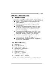
... not leave any unfastened small parts inside the case after installation. Before you start installing the motherboard, please make sure you follow the instructions below: „ Prepare a dry and stable working environment with sufficient lighting. „ Always disconnect the computer from power outlet before operation. „ Before you for ATX Case X 1 User's Manual X 1 Fully Setup Driver CD X 1 FDD Cable X 1 (optional) USB 2.0 Cable X1 (optional) S/PDIF out Cable X 1 (optional) Note: The package contents may...
... not leave any unfastened small parts inside the case after installation. Before you start installing the motherboard, please make sure you follow the instructions below: „ Prepare a dry and stable working environment with sufficient lighting. „ Always disconnect the computer from power outlet before operation. „ Before you for ATX Case X 1 User's Manual X 1 Fully Setup Driver CD X 1 FDD Cable X 1 (optional) USB 2.0 Cable X1 (optional) S/PDIF out Cable X 1 (optional) Note: The package contents may...

Setup Manual
Page 4
... PCI Express Gen2 x16 slot (x8) x1 Supports PCI-E Gen2 x16 expansion cards PCI Express x1 slot x2 Supports PCI-E x1 expansion cards On Board Floppy connector x1 Each connector supports 2 Floppy drives Connector Serial port Connector x1 Connects to 3 Gb/s. RAID 0 / 1 / 5 / 1+0 support Data transfer rates up to 3 Gb/s. eSATA Marvell 88SE6121 SATA Version 2.0 specification compliant. Fan Speed Controller Low Pin Count Interface ITE's "Smart Guardian" function Main Memory DIMM Slots x 4 Each DIMM supports 256MB / 512MB / 1GB / 2GB DDR2 Max Memory Capicity 8GB Dual Channel Mode...
... PCI Express Gen2 x16 slot (x8) x1 Supports PCI-E Gen2 x16 expansion cards PCI Express x1 slot x2 Supports PCI-E x1 expansion cards On Board Floppy connector x1 Each connector supports 2 Floppy drives Connector Serial port Connector x1 Connects to 3 Gb/s. RAID 0 / 1 / 5 / 1+0 support Data transfer rates up to 3 Gb/s. eSATA Marvell 88SE6121 SATA Version 2.0 specification compliant. Fan Speed Controller Low Pin Count Interface ITE's "Smart Guardian" function Main Memory DIMM Slots x 4 Each DIMM supports 256MB / 512MB / 1GB / 2GB DDR2 Max Memory Capicity 8GB Dual Channel Mode...
Setup Manual
Page 5
... in connector CPU Fan header System Fan header Clear CMOS header USB connector Power Connector (24pin) Power Connector (8pin) Power Connector (4pin) PS/2 Keyboard PS/2 Mouse Back Panel LAN port I/O USB Port Audio Jack eSATA Port Board Size 244 (W) x 305 (L) mm OS Support Windows 2000 / XP / VISTA TPower I45 SPEC x1 Supports front panel audio function x1 Supports CD audio-in function x2 Supports digital audio out function x1 Supports digital audio-in function x1 CPU Fan power supply (with Smart Fan function) x2 System Fan Power supply x1 Restore CMOS data to factory default x3...
... in connector CPU Fan header System Fan header Clear CMOS header USB connector Power Connector (24pin) Power Connector (8pin) Power Connector (4pin) PS/2 Keyboard PS/2 Mouse Back Panel LAN port I/O USB Port Audio Jack eSATA Port Board Size 244 (W) x 305 (L) mm OS Support Windows 2000 / XP / VISTA TPower I45 SPEC x1 Supports front panel audio function x1 Supports CD audio-in function x2 Supports digital audio out function x1 Supports digital audio-in function x1 CPU Fan power supply (with Smart Fan function) x2 System Fan Power supply x1 Restore CMOS data to factory default x3...
Setup Manual
Page 11
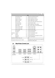
Dual Channel Memory installation To trigger the Dual Channel function of the same density in pairs, shown in the following table. Dual Channel Status DDR2_A1 DDR2_A2 DDR2_B1 DDR2_B2 Enabled O X O X Enabled X O X O Enabled O O O O (O means memory installed, X means memory not installed.) The DRAM bus width of the memory module must meet the following requirements: Install memory module of the motherboard, the memory module must be the same (x8 or x16) 9 C. TPower I45 B. Memory Capacity DIMM Socket Location DDR2 Module...
Dual Channel Memory installation To trigger the Dual Channel function of the same density in pairs, shown in the following table. Dual Channel Status DDR2_A1 DDR2_A2 DDR2_B1 DDR2_B2 Enabled O X O X Enabled X O X O Enabled O O O O (O means memory installed, X means memory not installed.) The DRAM bus width of the memory module must meet the following requirements: Install memory module of the motherboard, the memory module must be the same (x8 or x16) 9 C. TPower I45 B. Memory Capacity DIMM Socket Location DDR2 Module...
Setup Manual
Page 12
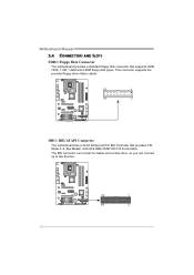
Motherboard Manual 2.4 CONNECTORS AND SLOTS FDD1: Floppy Disk Connector The motherboard provides a standard floppy disk connector that provides PIO Mode 0~4, Bus Master, and Ultra DMA 33/66/100/133 functionality. The IDE connector can connect a master and a slave drive, so you can connect up to two devices. 39 1 40 2 10 This connector supports the provided floppy drive ribbon cables. 33 1 34 2 IDE1: IDE/ATAPI Connector The motherboard has a 32-bit Enhanced PCI IDE Controller that supports 360K, 720K, 1.2M, 1.44M and 2.88M floppy disk types.
Motherboard Manual 2.4 CONNECTORS AND SLOTS FDD1: Floppy Disk Connector The motherboard provides a standard floppy disk connector that provides PIO Mode 0~4, Bus Master, and Ultra DMA 33/66/100/133 functionality. The IDE connector can connect a master and a slave drive, so you can connect up to two devices. 39 1 40 2 10 This connector supports the provided floppy drive ribbon cables. 33 1 34 2 IDE1: IDE/ATAPI Connector The motherboard has a 32-bit Enhanced PCI IDE Controller that supports 360K, 720K, 1.2M, 1.44M and 2.88M floppy disk types.
Setup Manual
Page 20
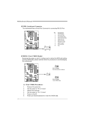
... 10 Key JCMOS1: Clear CMOS Header By placing the jumper on the AC. 6. Set the jumper to "Pin 2-3 close ". 5. Set the jumper to avoid damaging the motherboard. 3 1 Pin 1-2 Close: Normal Operation (default). 3 1 3 1 Pin 2-3 Close: Clear CMOS data. ※ Clear CMOS Procedures: 1. Power on pin2-3, it allows user to restore the BIOS safe setting and the CMOS data, please carefully follow the procedures to "Pin 1-2 close ". 3. Reset your desired password or clear the CMOS data. 18 Motherboard Manual JCOM1: Serial port Connector The motherboard has a Serial Port Connector for...
... 10 Key JCMOS1: Clear CMOS Header By placing the jumper on the AC. 6. Set the jumper to "Pin 2-3 close ". 5. Set the jumper to avoid damaging the motherboard. 3 1 Pin 1-2 Close: Normal Operation (default). 3 1 3 1 Pin 2-3 Close: Clear CMOS data. ※ Clear CMOS Procedures: 1. Power on pin2-3, it allows user to restore the BIOS safe setting and the CMOS data, please carefully follow the procedures to "Pin 1-2 close ". 3. Reset your desired password or clear the CMOS data. 18 Motherboard Manual JCOM1: Serial port Connector The motherboard has a Serial Port Connector for...
Setup Manual
Page 23
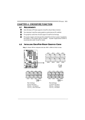
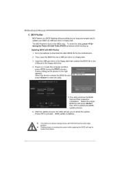
TPower I45 CHAPTER 4: CROSSFIRE FUNCTION 4.1 REQUIREMENTS Only Windows XP/Vista supports CrossFire (Dual Video) function. The graphics card driver should support CrossFire technology. The power supply unit must provide at least the minimum power required by the system, or the system will be unstable. A power supply above 500W is recommended under CrossFire mode. 4.2 INSTALLING CROSSFIRE-READY GRAPHICS CARDS Step 1: Power off the computer and set JPE1~JPE9 to Pin2-3 close. JPE1...
TPower I45 CHAPTER 4: CROSSFIRE FUNCTION 4.1 REQUIREMENTS Only Windows XP/Vista supports CrossFire (Dual Video) function. The graphics card driver should support CrossFire technology. The power supply unit must provide at least the minimum power required by the system, or the system will be unstable. A power supply above 500W is recommended under CrossFire mode. 4.2 INSTALLING CROSSFIRE-READY GRAPHICS CARDS Step 1: Power off the computer and set JPE1~JPE9 to Pin2-3 close. JPE1...

Setup Manual
Page 29
...To NorthBridge Latch [Auto] DRAM Frequency [Auto] DDR2 Enhanced Mode [Auto] > DRAM Timing Configuration > Clock Gen Configuration > Voltage Configuration Memory Test [Disabled] Options Normal Automate OverClock Manual OverClock Select Screen Select Item EnterGo to the BIOS Manual in this manual. Main Advanced BIOS SETUP UTILITY PCIPnP Boot Chipset O.N.E Exit Over-Clocking Navigator setting WARNING: Setting wrong values in below in the Setup CD. WARNING !! TPower I45 CHAPTER 6: T-POWER BIOS & SOFTWARE 6.1 T-POWER BIOS T-Power BIOS Features Overclocking Navigator Engine...
...To NorthBridge Latch [Auto] DRAM Frequency [Auto] DDR2 Enhanced Mode [Auto] > DRAM Timing Configuration > Clock Gen Configuration > Voltage Configuration Memory Test [Disabled] Options Normal Automate OverClock Manual OverClock Select Screen Select Item EnterGo to the BIOS Manual in this manual. Main Advanced BIOS SETUP UTILITY PCIPnP Boot Chipset O.N.E Exit Over-Clocking Navigator setting WARNING: Setting wrong values in below in the Setup CD. WARNING !! TPower I45 CHAPTER 6: T-POWER BIOS & SOFTWARE 6.1 T-POWER BIOS T-Power BIOS Features Overclocking Navigator Engine...
Setup Manual
Page 30
... CMOS Setting Nor[maxl9.0] CPU Frequency Setting Aut[o3m3a3t]e OverClock FSB(Bsel) To NorthBridge LatcMahn[uAaultoO]verClock DRAM Frequency [Auto] DDR2 Enhanced Mode [Auto] > DRAM Timing Configuration > Clock Gen Configuration > Voltage Configuration Memory Test [Disabled] Options Normal Automate OverClock Manual OverClock Select Screen Select Item EnterGo to Sub Screen F1 General Help F10 Save and Exit ESC Exit vxx.xx (C)Copyright 1985-200x, American Megatrends, Inc. ↓ Main Advanced PCIPnP BIOS SETUP UTILITY Boot Chipset O.N.E Exit Over-Clocking Navigator setting...
... CMOS Setting Nor[maxl9.0] CPU Frequency Setting Aut[o3m3a3t]e OverClock FSB(Bsel) To NorthBridge LatcMahn[uAaultoO]verClock DRAM Frequency [Auto] DDR2 Enhanced Mode [Auto] > DRAM Timing Configuration > Clock Gen Configuration > Voltage Configuration Memory Test [Disabled] Options Normal Automate OverClock Manual OverClock Select Screen Select Item EnterGo to Sub Screen F1 General Help F10 Save and Exit ESC Exit vxx.xx (C)Copyright 1985-200x, American Megatrends, Inc. ↓ Main Advanced PCIPnP BIOS SETUP UTILITY Boot Chipset O.N.E Exit Over-Clocking Navigator setting...

Setup Manual
Page 31
... single step. Over-Clocking Navigator [Normal] =========== Automate OverClock System =========== Auto OverClock System [V6-Tech Engine] Manual OverClock System Intel(R) SpeedStep(tm) tech [EnOapbtlieonds] Ratio CMOS Setting Nor[maxl9.0] CPU Frequency Setting Aut[o3m3a3t]e OverClock FSB(Bsel) To NorthBridge LatcMahn[uAaultoO]verClock DRAM Frequency [Auto] DDR2 Enhanced Mode [Auto] > DRAM Timing Configuration > Clock Gen Configuration > Voltage Configuration Memory Test [Disabled] Options Normal Automate OverClock Manual OverClock Select Screen Select Item EnterGo...
... single step. Over-Clocking Navigator [Normal] =========== Automate OverClock System =========== Auto OverClock System [V6-Tech Engine] Manual OverClock System Intel(R) SpeedStep(tm) tech [EnOapbtlieonds] Ratio CMOS Setting Nor[maxl9.0] CPU Frequency Setting Aut[o3m3a3t]e OverClock FSB(Bsel) To NorthBridge LatcMahn[uAaultoO]verClock DRAM Frequency [Auto] DDR2 Enhanced Mode [Auto] > DRAM Timing Configuration > Clock Gen Configuration > Voltage Configuration Memory Test [Disabled] Options Normal Automate OverClock Manual OverClock Select Screen Select Item EnterGo...

Setup Manual
Page 33
... System =========== Auto OverClock System [V6-Tech Engine] Manual OverClock System Intel(R) SpeedStep(tm) tech [Enabled] Ratio CMOS Setting [ x9.0] CPU Frequency Setting [333] FSB(Bsel) To NorthBridge Latch [Auto] DRAM Frequency [Auto] DDR2 Enhanced Mode [Auto] > DRAM Timing Configuration > Clock Gen Configuration > Voltage Configuration Memory Test [Enabled] Options Disabled Enabled Select Screen Select Item EnterGo to test memory compatibilities, and no extra devices or software are needed. Step 3 When the process is done, change the setting back from CMOS setup and...
... System =========== Auto OverClock System [V6-Tech Engine] Manual OverClock System Intel(R) SpeedStep(tm) tech [Enabled] Ratio CMOS Setting [ x9.0] CPU Frequency Setting [333] FSB(Bsel) To NorthBridge Latch [Auto] DRAM Frequency [Auto] DDR2 Enhanced Mode [Auto] > DRAM Timing Configuration > Clock Gen Configuration > Voltage Configuration Memory Test [Enabled] Options Disabled Enabled Select Screen Select Item EnterGo to test memory compatibilities, and no extra devices or software are needed. Step 3 When the process is done, change the setting back from CMOS setup and...
Setup Manual
Page 34
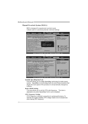
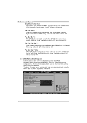
... to the USB port or the floppy disk drive. 4. BIOS update completes. To enter the utility, press during the POST process. Select the device contains the BIOS file and press to proceed. Press to enter the utility. 5. BIO-Flasher BIO-Flasher is built in the BIOS chip. z Shutting down or resetting the system while updating the BIOS will lead to perform the BIOS update process. 6. Select the proper BIOS file and press then to system boot failure. 32 Motherboard Manual C.
... to the USB port or the floppy disk drive. 4. BIOS update completes. To enter the utility, press during the POST process. Select the device contains the BIOS file and press to proceed. Press to enter the utility. 5. BIO-Flasher BIO-Flasher is built in the BIOS chip. z Shutting down or resetting the system while updating the BIOS will lead to perform the BIOS update process. 6. Select the proper BIOS file and press then to system boot failure. 32 Motherboard Manual C.

Setup Manual
Page 35
... Configuration > Hardware Health Configuration > Smart Fan Configuration > Power Configuration > Intel TXT(LT) Configuration > Intel VT-d Configuration > MPS Configuration > USB Configuration > Config Onboard PCI/PCI-E Devices O.N.E Exit Configure Smart Fan. This is controlled automatically by CPU/System temperature. This function will be seen under "Smart Fan Configuration" in below sections may cause system to inappropriate overclock actions. Main Advanced PCIPnP BIOS SETUP UTILITY Boot Chipset Advanced Settings WARNING: Setting wrong values in "Advanced Menu". Change Option...
... Configuration > Hardware Health Configuration > Smart Fan Configuration > Power Configuration > Intel TXT(LT) Configuration > Intel VT-d Configuration > MPS Configuration > USB Configuration > Config Onboard PCI/PCI-E Devices O.N.E Exit Configure Smart Fan. This is controlled automatically by CPU/System temperature. This function will be seen under "Smart Fan Configuration" in below sections may cause system to inappropriate overclock actions. Main Advanced PCIPnP BIOS SETUP UTILITY Boot Chipset Advanced Settings WARNING: Setting wrong values in "Advanced Menu". Change Option...
Setup Manual
Page 36
... Discard Changes Load Optimal Defaults Security Settings > Security CMOS Backup Function BIOS SETUP UTILITY Boot Chipset CMOS Backup Func CMOS Data Reload CMOS Data Save O.N.E Exit Select Screen Select Item EnterGo to reload any saved CMOS setting for customizing system configurations. Motherboard Manual Smart Fan Calibration Choose this set value. CMOS Reloading Program It allows users to this item and then the BIOS will turn off. Fan Ctrl On(℃) The CPU/System fan starts to save different CMOS settings into BIOS-ROM. The...
... Discard Changes Load Optimal Defaults Security Settings > Security CMOS Backup Function BIOS SETUP UTILITY Boot Chipset CMOS Backup Func CMOS Data Reload CMOS Data Save O.N.E Exit Select Screen Select Item EnterGo to reload any saved CMOS setting for customizing system configurations. Motherboard Manual Smart Fan Calibration Choose this set value. CMOS Reloading Program It allows users to this item and then the BIOS will turn off. Fan Ctrl On(℃) The CPU/System fan starts to save different CMOS settings into BIOS-ROM. The...
Setup Manual
Page 38
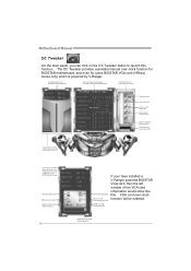
... VGA s etting file If your have installed a V-Ranger powered BIOSTAR VGA card, then the left window of the VGA card information would show . Tes t the VGA card Manual over - VGA card over -clock function for BIOSTAR motherboard, and even for some BIOSTAR VGA card (VR8xxx series only) which is a rea shows clo ck/vol ta ge infor matio n of th e VGA card Th is powered by V-Ranger. Motherboard Manual OC Tweaker On the main panel, you are not using a nVIDI A VGA...
... VGA s etting file If your have installed a V-Ranger powered BIOSTAR VGA card, then the left window of the VGA card information would show . Tes t the VGA card Manual over - VGA card over -clock function for BIOSTAR motherboard, and even for some BIOSTAR VGA card (VR8xxx series only) which is a rea shows clo ck/vol ta ge infor matio n of th e VGA card Th is powered by V-Ranger. Motherboard Manual OC Tweaker On the main panel, you are not using a nVIDI A VGA...
Setup Manual
Page 44
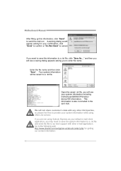
... system information to a .txt file and send the file to provide your system information while using eHot-Line service. Go to a .txt file, click "Save As..." Motherboard Manual After filling up this information to the following web http://www.biostar.com.tw/app/en-us/about/contact.php for your system information including motherboard/BIOS/CPU/video/ device/OS information. click "Send" to...
... system information to a .txt file and send the file to provide your system information while using eHot-Line service. Go to a .txt file, click "Save As..." Motherboard Manual After filling up this information to the following web http://www.biostar.com.tw/app/en-us/about/contact.php for your system information including motherboard/BIOS/CPU/video/ device/OS information. click "Send" to...

Setup Manual
Page 49
... are used for recovery 4 Flash Programming successful 5 File read error 7 No Flash EPROM detected 10 Flash Erase error 11 Flash Program error 12 "AMIBOOT.ROM" file size error 13 BIOS ROM image mismatch (file layout does not match image present in flash device) POST BIOS Beep Codes Number of Beeps Description 1 Memory refresh timer error 3 Base memory read/write test error 6 Keyboard controller BAT command failed 7 General exception error (processor exception interrupt error) 8 Display memory error (system video adapter) Troubleshooting POST BIOS Beep Codes Number...
... are used for recovery 4 Flash Programming successful 5 File read error 7 No Flash EPROM detected 10 Flash Erase error 11 Flash Program error 12 "AMIBOOT.ROM" file size error 13 BIOS ROM image mismatch (file layout does not match image present in flash device) POST BIOS Beep Codes Number of Beeps Description 1 Memory refresh timer error 3 Base memory read/write test error 6 Keyboard controller BAT command failed 7 General exception error (processor exception interrupt error) 8 Display memory error (system video adapter) Troubleshooting POST BIOS Beep Codes Number...

Setup Manual
Page 50
... keyboard controller command byte is OK. Set up application processors. Detects the presence of different Input Devices. Initializes different devices through DIM. Give control to determine if battery power is OK and CMOS checksum is being done on default values and clear passwords. Also initialize BIOS modules on CMOS setup questions. Verify CMOS checksum manually by reading storage area. Initializes both the 8259 compatible PICs in the system that have optional ROMs...
... keyboard controller command byte is OK. Set up application processors. Detects the presence of different Input Devices. Initializes different devices through DIM. Give control to determine if battery power is OK and CMOS checksum is being done on default values and clear passwords. Also initialize BIOS modules on CMOS setup questions. Verify CMOS checksum manually by reading storage area. Initializes both the 8259 compatible PICs in the system that have optional ROMs...

Setup Manual
Page 51
... INT09h vector. Prepare CPU for Int 19 boot. USB controllers are initialized at config display if needed / requested. Updates CMOS memory size from base memory. Please note this point. Save system context for Extended BIOS Data Area from memory found in system RAM size if needed. Mid POST initialization of chipset registers. Allocates memory for ACPI. Display errors to the user and gets the user response for DEL or ESC keys to OS Loader...
... INT09h vector. Prepare CPU for Int 19 boot. USB controllers are initialized at config display if needed / requested. Updates CMOS memory size from base memory. Please note this point. Save system context for Extended BIOS Data Area from memory found in system RAM size if needed. Mid POST initialization of chipset registers. Allocates memory for ACPI. Display errors to the user and gets the user response for DEL or ESC keys to OS Loader...


