
Setup Manual
Page 2
Table of Contents Chapter 1: Introduction 1 1.1 Before You Start 1 1.2 Package Checklist 1 1.3 Motherboard Features 2 1.4 Rear Panel Connectors 3 1.5 Motherboard Layout 4 Chapter 2: Hardware Installation 5 2.1 Installing Central Processing Unit (CPU 5 2.2 FAN Headers 7 2.3 Installing System Memory 8 2.4 Connectors and Slots 10 Chapter 3: Headers & Jumpers Setup 13 3.1 How to ...
Table of Contents Chapter 1: Introduction 1 1.1 Before You Start 1 1.2 Package Checklist 1 1.3 Motherboard Features 2 1.4 Rear Panel Connectors 3 1.5 Motherboard Layout 4 Chapter 2: Hardware Installation 5 2.1 Installing Central Processing Unit (CPU 5 2.2 FAN Headers 7 2.3 Installing System Memory 8 2.4 Connectors and Slots 10 Chapter 3: Headers & Jumpers Setup 13 3.1 How to ...
Setup Manual
Page 3
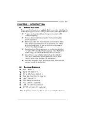
Before you start installing the motherboard, please make sure you follow the instructions below: „ Prepare a dry and stable working environment with sufficient lighting. „ Always disconnect the computer from power ... I/O Panel for choosing our product. CHAPTER 1: INTRODUCTION TPower I45 1.1 BEFORE YOU START Thank you take the motherboard out from anti-static bag, ground yourself properly by area or your motherboard version. 1 Hold the board on motherboard or the rear side of the board unless necessary. Loose parts will cause short circuits which may...
Before you start installing the motherboard, please make sure you follow the instructions below: „ Prepare a dry and stable working environment with sufficient lighting. „ Always disconnect the computer from power ... I/O Panel for choosing our product. CHAPTER 1: INTRODUCTION TPower I45 1.1 BEFORE YOU START Thank you take the motherboard out from anti-static bag, ground yourself properly by area or your motherboard version. 1 Hold the board on motherboard or the rear side of the board unless necessary. Loose parts will cause short circuits which may...

Setup Manual
Page 4
SATA II ICH10R SATA Version 2.0 specification compliant. Motherboard Manual 1.3 MOTHERBOARD FEATURES SPEC LGA 775 Supports Execute Disable Bit / Enhanced Intel Intel Core2Duo / Core2Quad / CPU SpeedStep® / Intel Architecture-64 / Extended Pentium Dual-Core / Celeron Dual-...
SATA II ICH10R SATA Version 2.0 specification compliant. Motherboard Manual 1.3 MOTHERBOARD FEATURES SPEC LGA 775 Supports Execute Disable Bit / Enhanced Intel Intel Core2Duo / Core2Quad / CPU SpeedStep® / Intel Architecture-64 / Extended Pentium Dual-Core / Celeron Dual-...

Setup Manual
Page 6
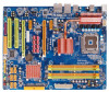
Motherboard Manual 1.5 MOTHERBOARD LAYOUT JKBMS1 JATXPWR1 LGA775 JUSB2 CPU1 JUSB1 JCFAN1 DDR2_A1 DDR2_A2 DDR2_B1 DDR2_B2 BIOS ESATAX1 JUSBV1 JRJ45USB1 JNFAN1 JAUDIO1 J1 Int el P45 JATXPWR2 PEX1_2 LAN PEX16_1 JCMOS1 JSPDIF_OUT2 JCDIN1 PEX1_1 JPE1 JPE3 JPE5 JPE7 JPE2 JPE4 JPE6 JPE8 JPE9 BAT1 Intel ICH10R SATA1 SATA2 PEX16 _2 CODEC PCI1 JSPDIF_OUT1 JAUDIOF1 JCOM1 PCI2 JSPDIF_IN1 FDD1 SATA3 Super IDE I/O IDE1 JUSBV2 JSFAN1 JUSB5 JUSB4 JUSB3 JPANEL1 RSTSW2 PWRSW1 Note: ■ represents the 1st pin. 4
Motherboard Manual 1.5 MOTHERBOARD LAYOUT JKBMS1 JATXPWR1 LGA775 JUSB2 CPU1 JUSB1 JCFAN1 DDR2_A1 DDR2_A2 DDR2_B1 DDR2_B2 BIOS ESATAX1 JUSBV1 JRJ45USB1 JNFAN1 JAUDIO1 J1 Int el P45 JATXPWR2 PEX1_2 LAN PEX16_1 JCMOS1 JSPDIF_OUT2 JCDIN1 PEX1_1 JPE1 JPE3 JPE5 JPE7 JPE2 JPE4 JPE6 JPE8 JPE9 BAT1 Intel ICH10R SATA1 SATA2 PEX16 _2 CODEC PCI1 JSPDIF_OUT1 JAUDIOF1 JCOM1 PCI2 JSPDIF_IN1 FDD1 SATA3 Super IDE I/O IDE1 JUSBV2 JSFAN1 JUSB5 JUSB4 JUSB3 JPANEL1 RSTSW2 PWRSW1 Note: ■ represents the 1st pin. 4

Setup Manual
Page 8
Motherboard Manual Step 2: Look for the triangular cut edge. Connect the CPU FAN power cable into the JCFAN1. Step 2-1: Step 2-2: Step 3: Hold the CPU down firmly, and then lower the lever to locked position to complete the installation. The CPU will fit only in the correct orientation. Step 4: Put the CPU Fan and heatsink assembly on the CPU and buckle it on CPU should point forwards this triangular cut edge on socket, and the golden dot on the retention frame. This completes the installation. 6
Motherboard Manual Step 2: Look for the triangular cut edge. Connect the CPU FAN power cable into the JCFAN1. Step 2-1: Step 2-2: Step 3: Hold the CPU down firmly, and then lower the lever to locked position to complete the installation. The CPU will fit only in the correct orientation. Step 4: Put the CPU Fan and heatsink assembly on the CPU and buckle it on CPU should point forwards this triangular cut edge on socket, and the golden dot on the retention frame. This completes the installation. 6

Setup Manual
Page 10
DD R2_A1 DD R2_A2 DD R2_B1 DD R2_B2 Motherboard Manual 2.3 INSTALLING SYSTEM MEMORY A. Insert the DIMM vertically and firmly into the slot until the retaining chip snap back in place and the DIMM is properly seated. 8 Unlock a DIMM slot by pressing the retaining clips outward. Memory Modules 1. Align a DIMM on the slot such that the notch on the DIMM matches the break on the Slot. 2.
DD R2_A1 DD R2_A2 DD R2_B1 DD R2_B2 Motherboard Manual 2.3 INSTALLING SYSTEM MEMORY A. Insert the DIMM vertically and firmly into the slot until the retaining chip snap back in place and the DIMM is properly seated. 8 Unlock a DIMM slot by pressing the retaining clips outward. Memory Modules 1. Align a DIMM on the slot such that the notch on the DIMM matches the break on the Slot. 2.
Setup Manual
Page 11
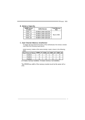
... O O O O (O means memory installed, X means memory not installed.) The DRAM bus width of the memory module must meet the following requirements: Install memory module of the motherboard, the memory module must be the same (x8 or x16) 9 TPower I45 B. Memory Capacity DIMM Socket Location DDR2 Module DDR2_A1 256MB/512MB/1GB/2GB DDR2_A2...
... O O O O (O means memory installed, X means memory not installed.) The DRAM bus width of the memory module must meet the following requirements: Install memory module of the motherboard, the memory module must be the same (x8 or x16) 9 TPower I45 B. Memory Capacity DIMM Socket Location DDR2 Module DDR2_A1 256MB/512MB/1GB/2GB DDR2_A2...
Setup Manual
Page 12
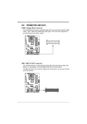
The IDE connector can connect a master and a slave drive, so you can connect up to two devices. 39 1 40 2 10 Motherboard Manual 2.4 CONNECTORS AND SLOTS FDD1: Floppy Disk Connector The motherboard provides a standard floppy disk connector that provides PIO Mode 0~4, Bus Master, and Ultra DMA 33/66/100/133 functionality. This connector supports the provided floppy drive ribbon cables. 33 1 34 2 IDE1: IDE/ATAPI Connector The motherboard has a 32-bit Enhanced PCI IDE Controller that supports 360K, 720K, 1.2M, 1.44M and 2.88M floppy disk types.
The IDE connector can connect a master and a slave drive, so you can connect up to two devices. 39 1 40 2 10 Motherboard Manual 2.4 CONNECTORS AND SLOTS FDD1: Floppy Disk Connector The motherboard provides a standard floppy disk connector that provides PIO Mode 0~4, Bus Master, and Ultra DMA 33/66/100/133 functionality. This connector supports the provided floppy drive ribbon cables. 33 1 34 2 IDE1: IDE/ATAPI Connector The motherboard has a 32-bit Enhanced PCI IDE Controller that supports 360K, 720K, 1.2M, 1.44M and 2.88M floppy disk types.

Setup Manual
Page 13
TPower I45 SATA1~SATA3: Serial ATA Connectors The motherboard has a PCI to SATA Controller with 6 channels SATA interface, it is designated as 32 bits. PCI1 PCI2 11 This PCI slot is a bus standard for expansion cards. SATA3 SATA2 SATA1 PCI1/PCI2: Peripheral Component Interconnect Slots This motherboard is equipped with transfer rate of 3.0Gb/s. PCI stands for Peripheral Component Interconnect, and it satisfies the SATA 2.0 spec and with 2 standard PCI slots.
TPower I45 SATA1~SATA3: Serial ATA Connectors The motherboard has a PCI to SATA Controller with 6 channels SATA interface, it is designated as 32 bits. PCI1 PCI2 11 This PCI slot is a bus standard for expansion cards. SATA3 SATA2 SATA1 PCI1/PCI2: Peripheral Component Interconnect Slots This motherboard is equipped with transfer rate of 3.0Gb/s. PCI stands for Peripheral Component Interconnect, and it satisfies the SATA 2.0 spec and with 2 standard PCI slots.

Setup Manual
Page 14
...When using CrossFire technology with multiple displays. PEX16_2 slot is master and runs with multiple displays. The design of this motherboard supports dual PCI-Express graphics cards using CrossFire, this slot is reserved for graphics or video cards. To configure for... an aggregate of configuring JPE1~JPE9. PCI-Express 1.0a compliant. - PCI-Express supports a raw bit-rate of this motherboard supports dual PCI-Express graphics cards using CrossFire. Maximum theoretical realized bandwidth of 8GB/s(4GB/s CrossFire) simultaneously per direction, for CrossFire...
...When using CrossFire technology with multiple displays. PEX16_2 slot is master and runs with multiple displays. The design of this motherboard supports dual PCI-Express graphics cards using CrossFire, this slot is reserved for graphics or video cards. To configure for... an aggregate of configuring JPE1~JPE9. PCI-Express 1.0a compliant. - PCI-Express supports a raw bit-rate of this motherboard supports dual PCI-Express graphics cards using CrossFire. Maximum theoretical realized bandwidth of 8GB/s(4GB/s CrossFire) simultaneously per direction, for CrossFire...

Setup Manual
Page 16
... will provide +12V to connect 24-pin power connector on the system, please make sure that both JATXPWR1 and JATXPWR2 connectors have been plugged-in. Motherboard Manual JATXPWR2: ATX Power Source Connector This connector allows user to CPU power circuit. 4 1 Pin Assignment 1 +12V 2 +12V 8 5 3 +12V 4 +12V 5 Ground 6 Ground 7 Ground 8 Ground Note...
... will provide +12V to connect 24-pin power connector on the system, please make sure that both JATXPWR1 and JATXPWR2 connectors have been plugged-in. Motherboard Manual JATXPWR2: ATX Power Source Connector This connector allows user to CPU power circuit. 4 1 Pin Assignment 1 +12V 2 +12V 8 5 3 +12V 4 +12V 5 Ground 6 Ground 7 Ground 8 Ground Note...

Setup Manual
Page 18
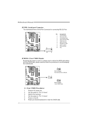
Motherboard Manual JAUDIOF1: Front Panel Audio Header This header allows user to connect the audio source from the variaty devices, like CD-ROM, DVD-ROM, PCI ...
Motherboard Manual JAUDIOF1: Front Panel Audio Header This header allows user to connect the audio source from the variaty devices, like CD-ROM, DVD-ROM, PCI ...
Setup Manual
Page 20
... safe setting and the CMOS data, please carefully follow the procedures to avoid damaging the motherboard. 3 1 Pin 1-2 Close: Normal Operation (default). 3 1 3 1 Pin 2-3 Close: Clear CMOS data. ※ Clear CMOS Procedures: 1. Motherboard Manual JCOM1: Serial port Connector The motherboard has a Serial Port Connector for five seconds. 4. Wait for connecting RS-232 Port. 9 1 10 2 Pin...
... safe setting and the CMOS data, please carefully follow the procedures to avoid damaging the motherboard. 3 1 Pin 1-2 Close: Normal Operation (default). 3 1 3 1 Pin 2-3 Close: Clear CMOS data. ※ Clear CMOS Procedures: 1. Motherboard Manual JCOM1: Serial port Connector The motherboard has a Serial Port Connector for five seconds. 4. Wait for connecting RS-232 Port. 9 1 10 2 Pin...

Setup Manual
Page 22
... Pin 1-2 Close JPE 9 31 Normal Operation PEX16_1: x16 Speed PEX16_2: Not Functional JPE 9 31 Pin 2-3 Close: CrossFire Operation PEX16_1: x8 Speed PEX16_2: x8 Speed 20 Motherboard Manual BIOS POST Code/CPU Temperature Indicator This indicator will show current CPU temperature.
... Pin 1-2 Close JPE 9 31 Normal Operation PEX16_1: x16 Speed PEX16_2: Not Functional JPE 9 31 Pin 2-3 Close: CrossFire Operation PEX16_1: x8 Speed PEX16_2: x8 Speed 20 Motherboard Manual BIOS POST Code/CPU Temperature Indicator This indicator will show current CPU temperature.

Setup Manual
Page 24
Motherboard Manual Step 2: Insert the two CrossFire-Ready graphics cards into PEX16_1 (Master) and PEX16_2 (Slave) PEX16_1(Mas ter ) PEX16_2(Slave) Notice: Make sure both the ...
Motherboard Manual Step 2: Insert the two CrossFire-Ready graphics cards into PEX16_1 (Master) and PEX16_2 (Slave) PEX16_1(Mas ter ) PEX16_2(Slave) Notice: Make sure both the ...

Setup Manual
Page 26
... 2 disk drives in the array. RAID techniques can reside on the same disk or on a second redundant drive in a RAID 1 array system. Should one drive. Motherboard Manual RAID 1: Every read and write is impaired during drive rebuilds. Fault Tolerance: Yes. The mirrored (backup) copy of the data can be applied...
... 2 disk drives in the array. RAID techniques can reside on the same disk or on a second redundant drive in a RAID 1 array system. Should one drive. Motherboard Manual RAID 1: Every read and write is impaired during drive rebuilds. Fault Tolerance: Yes. The mirrored (backup) copy of the data can be applied...

Setup Manual
Page 28
... ideal combination of good performance, good fault tolerance, and high capacity and storage efficiency. Drawbacks: Individual block data transfer rate same as a single disk. Motherboard Manual RAID 5 (For Onboard SATA Only): RAID 5 stripes both data and parity information across all the drives in the array. Disk 1 DATA 1 DATA 3 PARITY DATA...
... ideal combination of good performance, good fault tolerance, and high capacity and storage efficiency. Drawbacks: Individual block data transfer rate same as a single disk. Motherboard Manual RAID 5 (For Onboard SATA Only): RAID 5 stripes both data and parity information across all the drives in the array. Disk 1 DATA 1 DATA 3 PARITY DATA...
Setup Manual
Page 30
Motherboard Manual Manual Overclock System (M.O.S.) MOS is set the CPU ratio frequency. Intel(R) SpeedStep(tm) Tech This item allows you to set to Disabled. This item ...
Motherboard Manual Manual Overclock System (M.O.S.) MOS is set the CPU ratio frequency. Intel(R) SpeedStep(tm) Tech This item allows you to set to Disabled. This item ...

Setup Manual
Page 32
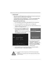
... > Clock Gen Configuration > Voltage Configuration Memory Test [Disabled] Options V6-Tech Engine V8-Tech Engine V12-Tech Engine Select Screen Select Item EnterGo to malfunction. Motherboard Manual V6 Tech Engine This engine will make a best over-clock performance. Main Advanced PCIPnP BIOS SETUP UTILITY Boot Chipset O.N.E Exit Over-Clocking Navigator setting...
... > Clock Gen Configuration > Voltage Configuration Memory Test [Disabled] Options V6-Tech Engine V8-Tech Engine V12-Tech Engine Select Screen Select Item EnterGo to malfunction. Motherboard Manual V6 Tech Engine This engine will make a best over-clock performance. Main Advanced PCIPnP BIOS SETUP UTILITY Boot Chipset O.N.E Exit Over-Clocking Navigator setting...
Setup Manual
Page 34
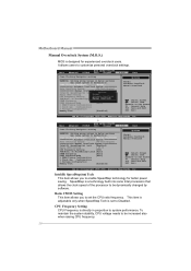
... the BIOS files and their respective information. Updating BIOS with FAT32/16 format and single partition. Press to download the latest BIOS file for the motherboard. 2. z This utility only allows storage device with BIO-Flasher 1. BIOS update completes. Go to the website to proceed. Power on the right appears. Then, save... drive or floppy disk. z Shutting down or resetting the system while updating the BIOS will lead to the USB port or the floppy disk drive. 4. Motherboard Manual C. BIO-Flasher BIO-Flasher is built in the BIOS chip.
... the BIOS files and their respective information. Updating BIOS with FAT32/16 format and single partition. Press to download the latest BIOS file for the motherboard. 2. z This utility only allows storage device with BIO-Flasher 1. BIOS update completes. Go to the website to proceed. Power on the right appears. Then, save... drive or floppy disk. z Shutting down or resetting the system while updating the BIOS will lead to the USB port or the floppy disk drive. 4. Motherboard Manual C. BIO-Flasher BIO-Flasher is built in the BIOS chip.

