
TForce4 SLI user's manual
Page 4
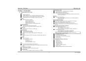
...-45 LAN jack. 1 PS/2 Mouse Port. 1 PS/2 Keyboard Port. 1 1394A Firewire Port. 1 Serial Port. (COM2 is 4GB, supporting 4 DIMM sockets. Environment Control initiatives, H/W Monitor Fan Speed Controller ITE's "Smart Guardian" function IDE 2 on-board connectors support 4 IDE ...400Mb/s. 1 TForce4 SLI Gigabit Ethernet LAN NVIDIA Gigabit MAC + VITESSE Gigabit PHY VSC8201. Two PCI-Express x1 slots: PEX1-1 and PEX1-2. Two Ultra DMA 133/100/66/33 IDE connectors. Biostar T-Series Chapter 1: Introduction 1.1 MOTHERBOARD FEATURES CPU Supports Socket 939. Note:...
...-45 LAN jack. 1 PS/2 Mouse Port. 1 PS/2 Keyboard Port. 1 1394A Firewire Port. 1 Serial Port. (COM2 is 4GB, supporting 4 DIMM sockets. Environment Control initiatives, H/W Monitor Fan Speed Controller ITE's "Smart Guardian" function IDE 2 on-board connectors support 4 IDE ...400Mb/s. 1 TForce4 SLI Gigabit Ethernet LAN NVIDIA Gigabit MAC + VITESSE Gigabit PHY VSC8201. Two PCI-Express x1 slots: PEX1-1 and PEX1-2. Two Ultra DMA 133/100/66/33 IDE connectors. Biostar T-Series Chapter 1: Introduction 1.1 MOTHERBOARD FEATURES CPU Supports Socket 939. Note:...

TForce4 SLI user's manual
Page 5
Biostar T-Series 1.2 LAYOUT AND COMPONENTS JATXPWR1 IDE1 JDDR_0V>3V IDE2 DIMM3 DIMM1 JSFAN2 JCFAN1 DIMM4 DIMM2 CPU1 Socket 939 JSATA2 JSATA1 JSATA4 JCI1 JSFAN1 JSATA3 JCMOS1 BAT1 JNBFAN1 PWRSW RSTSW FDD1 nForce4 SLI JUSB3 LED_DIMM LED_ JUSB2 5SB JUSBV1 LED_D1 LED_D2 JUSB1 J1394A1 IEEE 1394 Chip BIOS JPANEL1 TForce4 SLI SLI1 J1394PWR1 PEX16-1 PEX16-2 JSPDIF_OUT PEX1-1 PEX1...
Biostar T-Series 1.2 LAYOUT AND COMPONENTS JATXPWR1 IDE1 JDDR_0V>3V IDE2 DIMM3 DIMM1 JSFAN2 JCFAN1 DIMM4 DIMM2 CPU1 Socket 939 JSATA2 JSATA1 JSATA4 JCI1 JSFAN1 JSATA3 JCMOS1 BAT1 JNBFAN1 PWRSW RSTSW FDD1 nForce4 SLI JUSB3 LED_DIMM LED_ JUSB2 5SB JUSBV1 LED_D1 LED_D2 JUSB1 J1394A1 IEEE 1394 Chip BIOS JPANEL1 TForce4 SLI SLI1 J1394PWR1 PEX16-1 PEX16-2 JSPDIF_OUT PEX1-1 PEX1...

TForce4 SLI user's manual
Page 7
...939 CPU launched before Rev. Notes: To remove the DDR modules, push the ejector tabs at both sides of the slot outward at the same time, and pull the modules out vertically. C. "SS" represents Single Side DDR memory module. Star sign "*" represents leave the DIMM socket empty. DIMM2 DIMM4 DIMM1 DIMM3 TForce4 SLI...SS/DS * * * * SS/DS SS/DS SS/DS SS/DS SS/DS SS/DS D. Memory Space DIMM Socket Location DIMM1 DIMM2 DIMM3 DIMM4 DDR Module 128MB/256MB/512MB/1GB *1 128MB/256MB/512MB/1GB *1 128MB/256MB/512MB/1GB *1...and the DIMM is 4 GB. Biostar T-Series 2.2 SYSTEM MEMORY A.
...939 CPU launched before Rev. Notes: To remove the DDR modules, push the ejector tabs at both sides of the slot outward at the same time, and pull the modules out vertically. C. "SS" represents Single Side DDR memory module. Star sign "*" represents leave the DIMM socket empty. DIMM2 DIMM4 DIMM1 DIMM3 TForce4 SLI...SS/DS * * * * SS/DS SS/DS SS/DS SS/DS SS/DS SS/DS D. Memory Space DIMM Socket Location DIMM1 DIMM2 DIMM3 DIMM4 DDR Module 128MB/256MB/512MB/1GB *1 128MB/256MB/512MB/1GB *1 128MB/256MB/512MB/1GB *1...and the DIMM is 4 GB. Biostar T-Series 2.2 SYSTEM MEMORY A.


