

TForce4 SLI user's manual
Page 2
DDR Modules ...4 B. Memory Space...4 C. Biostar T-Series TForce4 SLI PACKAGE CHECKLIST ...I /O Slots:...5 B. Central Processing Unit (CPU) ...3 B. Know your CPU Version ...4 2.3 PERIPHERALS ...5 A. DDR Installation Notice...4 D. Connectors and Headers:...6 CHAPTER 3: NVIDIA SLI FUNCTION ...12 3.1 REQUIREMENTS...12 3.2 PLACING THE SLI-NF4 SELECTOR CARD ...12 3.3 THINGS TO NOTICE...13 3.4 INSTALLING SLI-READY GRAPHICS CARDS ...13 3.5 ENABLING MULTI-GPU FEATURE IN WINDOWS ...14 CHAPTER 4: NVIDIA...
DDR Modules ...4 B. Memory Space...4 C. Biostar T-Series TForce4 SLI PACKAGE CHECKLIST ...I /O Slots:...5 B. Central Processing Unit (CPU) ...3 B. Know your CPU Version ...4 2.3 PERIPHERALS ...5 A. DDR Installation Notice...4 D. Connectors and Headers:...6 CHAPTER 3: NVIDIA SLI FUNCTION ...12 3.1 REQUIREMENTS...12 3.2 PLACING THE SLI-NF4 SELECTOR CARD ...12 3.3 THINGS TO NOTICE...13 3.4 INSTALLING SLI-READY GRAPHICS CARDS ...13 3.5 ENABLING MULTI-GPU FEATURE IN WINDOWS ...14 CHAPTER 4: NVIDIA...
TForce4 SLI user's manual
Page 3
BIOS Update...18 B. Biostar T-Series TForce4 SLI CHAPTER 5: USEFUL HELP...18 5.1 AWARD BIOS BEEP CODE...18 5.2 EXTRA INFORMATION ...18 A. CPU Overheated...18 5.3 TROUBLESHOOTING ...19 GERMAN...20 FRENCH ...21 ITALIAN ...22 SPANISH...23 PORTUGUESE ...24 POLAND...25 RUSSIAN ...26 ARABIC ...27 JAPANESE ...28 iii User's Manual
BIOS Update...18 B. Biostar T-Series TForce4 SLI CHAPTER 5: USEFUL HELP...18 5.1 AWARD BIOS BEEP CODE...18 5.2 EXTRA INFORMATION ...18 A. CPU Overheated...18 5.3 TROUBLESHOOTING ...19 GERMAN...20 FRENCH ...21 ITALIAN ...22 SPANISH...23 PORTUGUESE ...24 POLAND...25 RUSSIAN ...26 ARABIC ...27 JAPANESE ...28 iii User's Manual
TForce4 SLI user's manual
Page 4
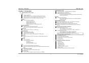
...PCI-Express slots: - One CD-ROM audio-in fastest networking performance. Back Panel I /O Chip: ITE IT8712F. Biostar T-Series Chapter 1: Introduction 1.1 MOTHERBOARD FEATURES CPU Supports Socket 939. Supports AMD Athlon 64 FX / Athlon 64 /Athlon 64 X2 processors. RAID 1 disk mirroring ..., with fault tolerance. Supports NVIDIA StreamThru technology Isochronous controller paired with transfer up to 400Mb/s. 1 TForce4 SLI Gigabit Ethernet LAN NVIDIA Gigabit MAC + VITESSE Gigabit PHY VSC8201. RAID 0+1 disk striping and mirroring for detail information...
...PCI-Express slots: - One CD-ROM audio-in fastest networking performance. Back Panel I /O Chip: ITE IT8712F. Biostar T-Series Chapter 1: Introduction 1.1 MOTHERBOARD FEATURES CPU Supports Socket 939. Supports AMD Athlon 64 FX / Athlon 64 /Athlon 64 X2 processors. RAID 1 disk mirroring ..., with fault tolerance. Supports NVIDIA StreamThru technology Isochronous controller paired with transfer up to 400Mb/s. 1 TForce4 SLI Gigabit Ethernet LAN NVIDIA Gigabit MAC + VITESSE Gigabit PHY VSC8201. RAID 0+1 disk striping and mirroring for detail information...

TForce4 SLI user's manual
Page 6
... When connecting with Smart Fan Control utilities. TForce4 SLI Step 4: Hold the CPU down firmly, and then lower the lever to locked position to a 90-degree angle. The CPU will fit only in the correct orientation. About FAN Headers CPU FAN Power Header: JCFAN1 System Fan Power ... should point towards this triangular cut edge on socket, and the golden dot on the retention frame. Biostar T-Series Chapter 2: Hardware Installations 2.1 CPU ASSEMBLY A. Central Processing Unit (CPU) Step 1: Remove the socket protection cap. Step 2: Pull the socket locking lever out from the ...
... When connecting with Smart Fan Control utilities. TForce4 SLI Step 4: Hold the CPU down firmly, and then lower the lever to locked position to a 90-degree angle. The CPU will fit only in the correct orientation. About FAN Headers CPU FAN Power Header: JCFAN1 System Fan Power ... should point towards this triangular cut edge on socket, and the golden dot on the retention frame. Biostar T-Series Chapter 2: Hardware Installations 2.1 CPU ASSEMBLY A. Central Processing Unit (CPU) Step 1: Remove the socket protection cap. Step 2: Pull the socket locking lever out from the ...

TForce4 SLI user's manual
Page 7
... both sides of the slot outward at the same time, and pull the modules out vertically. "DS" represents Double Side DDR memory module. Know your CPU Version AMD Athlon™ 64 Processor Ordering Part Number Example ADA 3200 A E P 5 AP Part Definition: AP = Rev C0 (see the table.../512MB/1GB *1 128MB/256MB/512MB/1GB *1 128MB/256MB/512MB/1GB *1 128MB/256MB/512MB/1GB *1 Total Memory Size Max is properly seated. C. Biostar T-Series 2.2 SYSTEM MEMORY A. Align a DIMM on the slot such that the notch on the DIMM matches the break on the slot. 2. DIMM2 DIMM4 DIMM1 DIMM3 TForce4 SLI B.
... both sides of the slot outward at the same time, and pull the modules out vertically. "DS" represents Double Side DDR memory module. Know your CPU Version AMD Athlon™ 64 Processor Ordering Part Number Example ADA 3200 A E P 5 AP Part Definition: AP = Rev C0 (see the table.../512MB/1GB *1 128MB/256MB/512MB/1GB *1 128MB/256MB/512MB/1GB *1 128MB/256MB/512MB/1GB *1 Total Memory Size Max is properly seated. C. Biostar T-Series 2.2 SYSTEM MEMORY A. Align a DIMM on the slot such that the notch on the DIMM matches the break on the slot. 2. DIMM2 DIMM4 DIMM1 DIMM3 TForce4 SLI B.

TForce4 SLI user's manual
Page 9
... 22 +5V 23 +5V 24 Ground TForce4 SLI ATX Power Source Connector: JATXPWR2 By connecting JATXPWR2, it will provide +12V to CPU power circuit. 21 34 Pin Assignment 1 +12V 2 +12V 3 Ground 4 Ground PCI-Express x16 Slot Power Source Connector: JPEXPWR1 When SLI mode is working under a stable environment. Biostar T-Series B. Please read Chapter 5 for detail...
... 22 +5V 23 +5V 24 Ground TForce4 SLI ATX Power Source Connector: JATXPWR2 By connecting JATXPWR2, it will provide +12V to CPU power circuit. 21 34 Pin Assignment 1 +12V 2 +12V 3 Ground 4 Ground PCI-Express x16 Slot Power Source Connector: JPEXPWR1 When SLI mode is working under a stable environment. Biostar T-Series B. Please read Chapter 5 for detail...

TForce4 SLI user's manual
Page 14
...PWRSW: This is an on diagnostics. On-Board Buttons There are 4 LED indicators on the motherboard to the table below for Power-on. TForce4 SLI RSTSW 2 PSRSW1 LED_D1 LED_D2 LED_DIMM LED_5SB LED_D1 and LED_D2: These 2 LED indicate system power on -board Reset button. 11 User's Manual LED_DIMM... is ready for different messages: LED_D1 LED_D2 Message ON ON Normal ON OFF Memory Error OFF ON VGA Error OFF OFF Abnormal: CPU / Chipset error. Biostar T-Series On-Board LED Indicators There are 2 on -board Power Switch button. RSTSW: This is an on -board buttons. ...
...PWRSW: This is an on diagnostics. On-Board Buttons There are 4 LED indicators on the motherboard to the table below for Power-on. TForce4 SLI RSTSW 2 PSRSW1 LED_D1 LED_D2 LED_DIMM LED_5SB LED_D1 and LED_D2: These 2 LED indicate system power on -board Reset button. 11 User's Manual LED_DIMM... is ready for different messages: LED_D1 LED_D2 Message ON ON Normal ON OFF Memory Error OFF ON VGA Error OFF OFF Abnormal: CPU / Chipset error. Biostar T-Series On-Board LED Indicators There are 2 on -board Power Switch button. RSTSW: This is an on -board buttons. ...
TForce4 SLI user's manual
Page 21
... into floppy drive and press Enter. 6. TForce4 SLI B. Clear the CMOS data. (See "JCMOS1: Clear CMOS Header" section) 2. Type "Awdflash xxxx.bf/sn/py/r" in the power cord and boot up to restore the BIOS: 1. The CPU cooler surface is fulfilling the CPU speed. Wait for a few seconds. 3. Biostar T-Series CHAPTER 5: USEFUL HELP 5.1 AWARD BIOS...
... into floppy drive and press Enter. 6. TForce4 SLI B. Clear the CMOS data. (See "JCMOS1: Clear CMOS Header" section) 2. Type "Awdflash xxxx.bf/sn/py/r" in the power cord and boot up to restore the BIOS: 1. The CPU cooler surface is fulfilling the CPU speed. Wait for a few seconds. 3. Biostar T-Series CHAPTER 5: USEFUL HELP 5.1 AWARD BIOS...
TForce4 SLI BIOS setup guide
Page 3
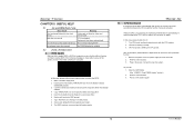
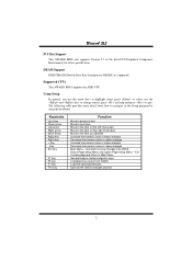
Quit and not save changes into CMOS Status Page Setup Menu and Option Page Setup Menu - Supported CPUs This AWARD BIOS supports the AMD CPU. Keystroke Up arrow Down arrow Left arrow Right arrow Move Enter PgUp key PgDn key + Key - Exit Current page and return to Main...make changes Decrease the numeric value or make changes Increase the numeric value or make changes Decrease the numeric value or make changes Main Menu - TForce4 SLI PCI Bus Support This AWARD BIOS also supports Version 2.1 of the Intel PCI (Peripheral Component Interconnect) local bus specification. Using Setup In general,...
Quit and not save changes into CMOS Status Page Setup Menu and Option Page Setup Menu - Supported CPUs This AWARD BIOS supports the AMD CPU. Keystroke Up arrow Down arrow Left arrow Right arrow Move Enter PgUp key PgDn key + Key - Exit Current page and return to Main...make changes Decrease the numeric value or make changes Increase the numeric value or make changes Decrease the numeric value or make changes Main Menu - TForce4 SLI PCI Bus Support This AWARD BIOS also supports Version 2.1 of the Intel PCI (Peripheral Component Interconnect) local bus specification. Using Setup In general,...

TForce4 SLI BIOS setup guide
Page 10
Disabled Disable cache. 9 TForce4 SLI 3 Advanced BIOS Features Figure 3. Enabled (default) Enable cache. Advanced BIOS Setup Cache Setup These BIOS attempt to load the operating system from the device in the sequence selected in these items. CPU Internal Cache Depending on the CPU/chipset in use, you may be able to increase memory access time with this option.
Disabled Disable cache. 9 TForce4 SLI 3 Advanced BIOS Features Figure 3. Enabled (default) Enable cache. Advanced BIOS Setup Cache Setup These BIOS attempt to load the operating system from the device in the sequence selected in these items. CPU Internal Cache Depending on the CPU/chipset in use, you may be able to increase memory access time with this option.
TForce4 SLI BIOS setup guide
Page 11
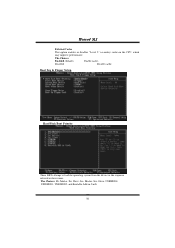
The Choices: Enabled (default) Enable cache. Master, Pri. Master, Sec, Slave, USBHDD0, USB HDD1, USB HDD2, and Bootable Add-in these items. The Choices: Pri. Boot Seq & Floppy Setup Hard Disk Boot Priority These BIOS attempt to load the operating system from the device in the sequence selected in Cards. 10 Slave, Sec. Disabled Disable cache. TForce4 SLI External Cache This option enables or disables "Level 2" secondary cache on the CPU, which may improve performance.
The Choices: Enabled (default) Enable cache. Master, Pri. Master, Sec, Slave, USBHDD0, USB HDD1, USB HDD2, and Bootable Add-in these items. The Choices: Pri. Boot Seq & Floppy Setup Hard Disk Boot Priority These BIOS attempt to load the operating system from the device in the sequence selected in Cards. 10 Slave, Sec. Disabled Disable cache. TForce4 SLI External Cache This option enables or disables "Level 2" secondary cache on the CPU, which may improve performance.
TForce4 SLI BIOS setup guide
Page 13
... required for OS2 systems with passwords to bring the system online and/or to enable/ disable display the Summary Screen Show. Note: If the CPU type is required to the operating system. The Choices: Non-OS2 (default), OS2. OS Select For DRAM > 64MB A choice other than ...1000. Select version supported by the operation system running on this item will be always"Enabled". This will enable only individuals with memory exceeding 64MB. TForce4 SLI Typematic Rate (Chars/Sec) Sets the rate at which a keystroke is only used for the system to boot and is held down . Setup ...
... required for OS2 systems with passwords to bring the system online and/or to enable/ disable display the Summary Screen Show. Note: If the CPU type is required to the operating system. The Choices: Non-OS2 (default), OS2. OS Select For DRAM > 64MB A choice other than ...1000. Select version supported by the operation system running on this item will be always"Enabled". This will enable only individuals with memory exceeding 64MB. TForce4 SLI Typematic Rate (Chars/Sec) Sets the rate at which a keystroke is only used for the system to boot and is held down . Setup ...

TForce4 SLI BIOS setup guide
Page 14
...optimized and therefore should not be changed unless you to system memory resources, such as DRAM. The Choices: Disabled (default), Enable. TForce4 SLI 4 Advanced Chipset Features This submenu allows you to disable \ enable the SATA spread spectrum function. The default settings that came with the...link. This chipset manage bus speeds and access to control the utilized width of the outgoing side of K8 CPU. The Choices: Disabled (default), Enable. 13 CPU Spread Spectrum The Choices: Center Spread (default). It also coordinates communications with your system. Advanced Chipset Setup ...
...optimized and therefore should not be changed unless you to system memory resources, such as DRAM. The Choices: Disabled (default), Enable. TForce4 SLI 4 Advanced Chipset Features This submenu allows you to disable \ enable the SATA spread spectrum function. The default settings that came with the...link. This chipset manage bus speeds and access to control the utilized width of the outgoing side of K8 CPU. The Choices: Disabled (default), Enable. 13 CPU Spread Spectrum The Choices: Center Spread (default). It also coordinates communications with your system. Advanced Chipset Setup ...

TForce4 SLI BIOS setup guide
Page 22
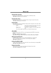
..., 5 Min, 6 Min, 7 Min, 8 Min, 9 Min, 10 Min, 11 Min, 12 Min, 13 Min, 14 Min, 15Min. The Choices: Delay 4 Sec, Instant-Off (default). to 1 hr. TForce4 SLI HDD Power Down = 15 min Max. to 15 min. Power Saving Maximum power management only available for more than 4 seconds forces the system to set... time of the ranges are from 1 min. Soft-Off by PWR-BTTN Pressing the power button for sl CPU's. HDD Power Down = 1 min. and disable. The Choices: Stop Grant, PwrOn Suspend.
..., 5 Min, 6 Min, 7 Min, 8 Min, 9 Min, 10 Min, 11 Min, 12 Min, 13 Min, 14 Min, 15Min. The Choices: Delay 4 Sec, Instant-Off (default). to 1 hr. TForce4 SLI HDD Power Down = 15 min Max. to 15 min. Power Saving Maximum power management only available for more than 4 seconds forces the system to set... time of the ranges are from 1 min. Soft-Off by PWR-BTTN Pressing the power button for sl CPU's. HDD Power Down = 1 min. and disable. The Choices: Stop Grant, PwrOn Suspend.
TForce4 SLI BIOS setup guide
Page 24
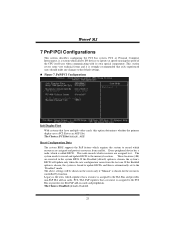
... above settings will update only when the new configuration varies from conflict. PnP/PCI Configurations Init Display First With systems that a resource is called ESCD. TForce4 SLI 7 PnP/PCI Configurations This section describes configuring the PCI bus system. Reset Configuration Data The system BIOS supports the PnP feature which signifies that have... Interconnect, is automatically set to the memory locations. Legacy is the term, which requires the system to operate at speeds nearing the speed of the CPU itself uses when communicating with its own special components.
... above settings will update only when the new configuration varies from conflict. PnP/PCI Configurations Init Display First With systems that a resource is called ESCD. TForce4 SLI 7 PnP/PCI Configurations This section describes configuring the PCI bus system. Reset Configuration Data The system BIOS supports the PnP feature which signifies that have... Interconnect, is automatically set to the memory locations. Legacy is the term, which requires the system to operate at speeds nearing the speed of the CPU itself uses when communicating with its own special components.

TForce4 SLI BIOS setup guide
Page 26
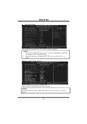
Show H/W Monitor in POST If your CPU FAN to choose. CPU Vcore/ +1.5V+3.3V/ +5.0V/ +12.0V/ 5VSB/ Voltage Battery Detect the system's voltage status automatically. 25 Shutdown Temperature This item allows you to enable or ... Health Status Chassis Open Warning This item allows you to reduce noise. CPU FAN Control by The Choice "smart" can make your computer contains a monitoring system, it will show PC health status during POST stage. The Choices: Disabled (default), Enabled. TForce4 SLI 8 PC Health Status A、Figure 8. The item offers several delay time...
Show H/W Monitor in POST If your CPU FAN to choose. CPU Vcore/ +1.5V+3.3V/ +5.0V/ +12.0V/ 5VSB/ Voltage Battery Detect the system's voltage status automatically. 25 Shutdown Temperature This item allows you to enable or ... Health Status Chassis Open Warning This item allows you to reduce noise. CPU FAN Control by The Choice "smart" can make your computer contains a monitoring system, it will show PC health status during POST stage. The Choices: Disabled (default), Enabled. TForce4 SLI 8 PC Health Status A、Figure 8. The item offers several delay time...

TForce4 SLI BIOS setup guide
Page 27
... Speed This field displays the current speed of the CPU. Current SYS FAN Speed This field displays the current speed SYSTEM fan. Shutdown Temperature This item allows you to reduce noise. TForce4 SLI CPU Temperature This field displays the current temperature of CPU fan. This item only effective under Windows 98 ACPI mode. The Choices...
... Speed This field displays the current speed of the CPU. Current SYS FAN Speed This field displays the current speed SYSTEM fan. Shutdown Temperature This item allows you to reduce noise. TForce4 SLI CPU Temperature This field displays the current temperature of CPU fan. This item only effective under Windows 98 ACPI mode. The Choices...

TForce4 SLI BIOS setup guide
Page 28
...(default). Show H/W Monitor in POST If your computer contains a monitoring system, it will turn off. Start PWM Value The Choices: 32 (default). CPU Vcore/ +1.5V+3.3V/ +5.0V/ +12.0V/ 5V/ Voltage Battery Detect the system's voltage status automatically. The item offers several delay time for ...lower than the set value, FAN will show PC health status during POST stage. The Choices: 52(default). TForce4 SLI CPU Fan Off If the CPU Temperature is arriving the set value, the CPU fan will work under Full Speed. Slope PWM The Choices: 1 PWM Value/℃(default), 2 PWM Value/℃...
...(default). Show H/W Monitor in POST If your computer contains a monitoring system, it will turn off. Start PWM Value The Choices: 32 (default). CPU Vcore/ +1.5V+3.3V/ +5.0V/ +12.0V/ 5V/ Voltage Battery Detect the system's voltage status automatically. The item offers several delay time for ...lower than the set value, FAN will show PC health status during POST stage. The Choices: 52(default). TForce4 SLI CPU Fan Off If the CPU Temperature is arriving the set value, the CPU fan will work under Full Speed. Slope PWM The Choices: 1 PWM Value/℃(default), 2 PWM Value/℃...
TForce4 SLI BIOS setup guide
Page 31
Cautions: 1. the difference will raise about 25%~30% of AMD CPU perform above overclock setting ideally; Manual Overclock System (M.O.S.) MOS is the best CPU type for experienced overclock users. Cautions: According tests have been done; It allows users to customize personal overclock setting. AMD 3000+ CPU is designed for overclock function. 30 From BET experiment, the Atholon64 FX CPU are not suitable for this A.O.S. feature. TForce4 SLI V12 Tech Engine This setting will be based on the selected CPU model. 2. Not all types of whole system performance.
Cautions: 1. the difference will raise about 25%~30% of AMD CPU perform above overclock setting ideally; Manual Overclock System (M.O.S.) MOS is the best CPU type for experienced overclock users. Cautions: According tests have been done; It allows users to customize personal overclock setting. AMD 3000+ CPU is designed for overclock function. 30 From BET experiment, the Atholon64 FX CPU are not suitable for this A.O.S. feature. TForce4 SLI V12 Tech Engine This setting will be based on the selected CPU model. 2. Not all types of whole system performance.

TForce4 SLI BIOS setup guide
Page 32
...from the selected CPU types. The Choices: StartUp (default),1.725V,1.700V,1.675V,1.650V,1.625V,1.600V etc. The Choices: StartUp (default),X4 800MHz, X5 1000MHz, X6 1200MHz, X7 1400MHz, X8 1600MHz, X9 1800MHz, etc. The Choices: 4x (default),1x,2x,3x,5x.Auto,x4. TForce4 SLI CPU Voltage This ...item allows you to select the CPU Frequency. NB/SB Voltage Regulator The Choices:1.52V(default),1.60V,1.68V,1.76V. Memory Voltage The Choices:2.60V(default),2.70V,2.80V...
...from the selected CPU types. The Choices: StartUp (default),1.725V,1.700V,1.675V,1.650V,1.625V,1.600V etc. The Choices: StartUp (default),X4 800MHz, X5 1000MHz, X6 1200MHz, X7 1400MHz, X8 1600MHz, X9 1800MHz, etc. The Choices: 4x (default),1x,2x,3x,5x.Auto,x4. TForce4 SLI CPU Voltage This ...item allows you to select the CPU Frequency. NB/SB Voltage Regulator The Choices:1.52V(default),1.60V,1.68V,1.76V. Memory Voltage The Choices:2.60V(default),2.70V,2.80V...


