
TForce4 SLI user's manual
Page 4
.../s. 1 TForce4 SLI Gigabit Ethernet LAN NVIDIA Gigabit MAC + VITESSE Gigabit PHY VSC8201. SLI Mode PCI-Express slots: - Notice: Normal Mode and SLI Mode are switched by filtering unauthorized traffic. Maximum memory space is optional.) 4 USB 2.0 Ports. 6 audio ports support 8 channels audio-out facilities. AMD 64 architecture enables simultaneous 32 and 64 bit computing. Biostar T-Series...
.../s. 1 TForce4 SLI Gigabit Ethernet LAN NVIDIA Gigabit MAC + VITESSE Gigabit PHY VSC8201. SLI Mode PCI-Express slots: - Notice: Normal Mode and SLI Mode are switched by filtering unauthorized traffic. Maximum memory space is optional.) 4 USB 2.0 Ports. 6 audio ports support 8 channels audio-out facilities. AMD 64 architecture enables simultaneous 32 and 64 bit computing. Biostar T-Series...

TForce4 SLI user's manual
Page 5
... I/O User's Manual Biostar T-Series 1.2 LAYOUT AND COMPONENTS JATXPWR1 IDE1 JDDR_0V>3V IDE2 DIMM3 DIMM1 JSFAN2 JCFAN1 DIMM4 DIMM2 CPU1 Socket 939 JSATA2 JSATA1 JSATA4 JCI1 JSFAN1 JSATA3 JCMOS1 BAT1 JNBFAN1 PWRSW RSTSW FDD1 nForce4 SLI JUSB3 LED_DIMM LED_ JUSB2 5SB JUSBV1 LED_D1 LED_D2 JUSB1 J1394A1 IEEE 1394 Chip BIOS JPANEL1 TForce4 SLI SLI1 J1394PWR1 PEX16...
... I/O User's Manual Biostar T-Series 1.2 LAYOUT AND COMPONENTS JATXPWR1 IDE1 JDDR_0V>3V IDE2 DIMM3 DIMM1 JSFAN2 JCFAN1 DIMM4 DIMM2 CPU1 Socket 939 JSATA2 JSATA1 JSATA4 JCI1 JSFAN1 JSATA3 JCMOS1 BAT1 JNBFAN1 PWRSW RSTSW FDD1 nForce4 SLI JUSB3 LED_DIMM LED_ JUSB2 5SB JUSBV1 LED_D1 LED_D2 JUSB1 J1394A1 IEEE 1394 Chip BIOS JPANEL1 TForce4 SLI SLI1 J1394PWR1 PEX16...

TForce4 SLI user's manual
Page 7
... D0 Part Definition BN BP BO BY BW Revision Rev E4 Rev E3 Rev E3 Rev E6 Rev E6 4 User's Manual DIMM2 DIMM4 DIMM1 DIMM3 TForce4 SLI B. "DS" represents Double Side DDR memory module. Unlock a DIMM slot by pressing the retaining clips outward. C. DIMM1 DIMM2 DIMM3 DIMM4 SS/DS * * * *...SS/DS SS/DS SS/DS SS/DS D. DDR Installation Notice For AMD K8 939 CPU launched before Rev. "SS" represents Single Side DDR memory module. Star sign "*" represents leave the DIMM socket empty. Biostar T-Series 2.2 SYSTEM MEMORY A. DDR Modules 1. Memory Space DIMM Socket Location DIMM1 DIMM2...
... D0 Part Definition BN BP BO BY BW Revision Rev E4 Rev E3 Rev E3 Rev E6 Rev E6 4 User's Manual DIMM2 DIMM4 DIMM1 DIMM3 TForce4 SLI B. "DS" represents Double Side DDR memory module. Unlock a DIMM slot by pressing the retaining clips outward. C. DIMM1 DIMM2 DIMM3 DIMM4 SS/DS * * * *...SS/DS SS/DS SS/DS SS/DS D. DDR Installation Notice For AMD K8 939 CPU launched before Rev. "SS" represents Single Side DDR memory module. Star sign "*" represents leave the DIMM socket empty. Biostar T-Series 2.2 SYSTEM MEMORY A. DDR Modules 1. Memory Space DIMM Socket Location DIMM1 DIMM2...
TForce4 SLI BIOS setup guide
Page 13
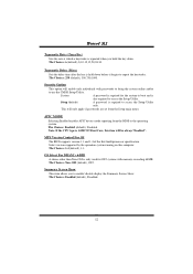
... Intel multiprocessor specification. The Choices: Enabled (default), Disabled. 12 The Choices: 250 (default), 500,750,1000. Note: If the CPU type is AMD 939 Dual Core, this computer. Typematic Delay (Msec) Sets the delay time after the key is held down . The Choices: Non-OS2 (default), OS2. ... reporting from the Setup main menu. Summary Screen Show This item allows you hold the key down before it begins to repeat the keystroke. TForce4 SLI Typematic Rate (Chars/Sec) Sets the rate at which a keystroke is repeated when you to enable/ disable display the Summary Screen Show....
... Intel multiprocessor specification. The Choices: Enabled (default), Disabled. 12 The Choices: 250 (default), 500,750,1000. Note: If the CPU type is AMD 939 Dual Core, this computer. Typematic Delay (Msec) Sets the delay time after the key is held down . The Choices: Non-OS2 (default), OS2. ... reporting from the Setup main menu. Summary Screen Show This item allows you hold the key down before it begins to repeat the keystroke. TForce4 SLI Typematic Rate (Chars/Sec) Sets the rate at which a keystroke is repeated when you to enable/ disable display the Summary Screen Show....
