
TForce4 SLI user's manual
Page 4
...2.0 Ports. 6 audio ports support 8 channels audio-out facilities. Serial ATA nForce4 SLI supports SATA 2.0 specification, with transfer up to 400Mb/s. 1 TForce4 SLI Gigabit Ethernet LAN NVIDIA Gigabit MAC + VITESSE Gigabit PHY VSC8201. Super I /O ...PCI-Express slots: - Two PCI-Express x8 slots: PEX16-1 and PEX16-2. - User's Manual Chipset NVIDIA nForce4 SLI, supports: Supports NVIDIA Firewall. Supports Gigabit Ethernet. Supports NVIDIA... IDE connectors. Biostar T-Series Chapter 1: Introduction 1.1 MOTHERBOARD FEATURES CPU Supports Socket 939.
...2.0 Ports. 6 audio ports support 8 channels audio-out facilities. Serial ATA nForce4 SLI supports SATA 2.0 specification, with transfer up to 400Mb/s. 1 TForce4 SLI Gigabit Ethernet LAN NVIDIA Gigabit MAC + VITESSE Gigabit PHY VSC8201. Super I /O ...PCI-Express slots: - Two PCI-Express x8 slots: PEX16-1 and PEX16-2. - User's Manual Chipset NVIDIA nForce4 SLI, supports: Supports NVIDIA Firewall. Supports Gigabit Ethernet. Supports NVIDIA... IDE connectors. Biostar T-Series Chapter 1: Introduction 1.1 MOTHERBOARD FEATURES CPU Supports Socket 939.

TForce4 SLI user's manual
Page 11
... 2 SPDIF OUT 3 Ground 31 Power Source Header for 1394 Chip: J1394PWR1 3 1 Pin 1-2 Close: +3.3V for 1394 chipset (default). 3 1 Pin 2-3 Close: +3.3V SB for 1394 chipset. 31 TForce4 SLI Power Source Header for USB Ports at Front Panel: JUSBV1 Pin 1-2 Close: +5V for USB ports at Front Panel: J1394A1...standby voltage. 3 1 Pin 1-2 Close (default) 3 1 Pin 2-3 Close Note: In order to connect the PCI bracket SPDIF output header. Biostar T-Series Digital Audio-out Connector: JSPDIF_OUT This connector allows users to support this function "Power-on system via USB device," JUSBV1 jumper cap should be...
... 2 SPDIF OUT 3 Ground 31 Power Source Header for 1394 Chip: J1394PWR1 3 1 Pin 1-2 Close: +3.3V for 1394 chipset (default). 3 1 Pin 2-3 Close: +3.3V SB for 1394 chipset. 31 TForce4 SLI Power Source Header for USB Ports at Front Panel: JUSBV1 Pin 1-2 Close: +5V for USB ports at Front Panel: J1394A1...standby voltage. 3 1 Pin 1-2 Close (default) 3 1 Pin 2-3 Close Note: In order to connect the PCI bracket SPDIF output header. Biostar T-Series Digital Audio-out Connector: JSPDIF_OUT This connector allows users to support this function "Power-on system via USB device," JUSBV1 jumper cap should be...

TForce4 SLI user's manual
Page 14
... Error OFF ON VGA Error OFF OFF Abnormal: CPU / Chipset error. PWRSW: This is an on -board buttons. LED_5SB: This LED indicates the system is activated normally. Biostar T-Series On-Board LED Indicators There are 2 on -board Reset button. 11 User's Manual TForce4 SLI RSTSW 2 PSRSW1 LED_D1 LED_D2 LED_DIMM LED_5SB LED_D1 and LED_D2: These...
... Error OFF ON VGA Error OFF OFF Abnormal: CPU / Chipset error. PWRSW: This is an on -board buttons. LED_5SB: This LED indicates the system is activated normally. Biostar T-Series On-Board LED Indicators There are 2 on -board Reset button. 11 User's Manual TForce4 SLI RSTSW 2 PSRSW1 LED_D1 LED_D2 LED_DIMM LED_5SB LED_D1 and LED_D2: These...
TForce4 SLI BIOS setup guide
Page 1
TForce4 SLI BIOS Setup BIOS Setup 1 1 Main Menu ...3 2 Standard CMOS Features 6 3 Advanced BIOS Features 9 4 Advanced Chipset Features 13 5 Integrated Peripherals ...15 6 Power Management Setup 20 7 PnP/PCI Configurations 23 8 PC Health Status...25 9 Over Clock Navigator Engine 28 10 CMOS Reload Program 34 i
TForce4 SLI BIOS Setup BIOS Setup 1 1 Main Menu ...3 2 Standard CMOS Features 6 3 Advanced BIOS Features 9 4 Advanced Chipset Features 13 5 Integrated Peripherals ...15 6 Power Management Setup 20 7 PnP/PCI Configurations 23 8 PC Health Status...25 9 Over Clock Navigator Engine 28 10 CMOS Reload Program 34 i

TForce4 SLI BIOS setup guide
Page 2
... stored in your system using Setup. ACPI Support Award ACPI BIOS support Version 1.0 of configuring your computer system's ROM (Read Only Memory) is turned off. TForce4 SLI BIOS Setup Introduction This manual discussed Award™ Setup program built into the ROM BIOS. The Award BIOS™ installed in battery-backed RAM so...
... stored in your system using Setup. ACPI Support Award ACPI BIOS support Version 1.0 of configuring your computer system's ROM (Read Only Memory) is turned off. TForce4 SLI BIOS Setup Introduction This manual discussed Award™ Setup program built into the ROM BIOS. The Award BIOS™ installed in battery-backed RAM so...

TForce4 SLI BIOS setup guide
Page 4
... configure certain IDE hard drive options and Programmed Input/ Output features. 3 Integrated Peripherals This submenu allows you to configure special chipset features. Advanced BIOS Features This submenu allows you to select from several setup functions. Main Menu Standard CMOS Features This submenu... to accept and enter the sub-menu. !! The information about BIOS defaults on manual (Figure 1,2,3,4,5,6,7,8,9) is just for update information. TForce4 SLI 1 Main Menu Once you enter Award BIOS™ CMOS Setup Utility, the Main Menu will appear on board, for reference, please...
... configure certain IDE hard drive options and Programmed Input/ Output features. 3 Integrated Peripherals This submenu allows you to configure special chipset features. Advanced BIOS Features This submenu allows you to select from several setup functions. Main Menu Standard CMOS Features This submenu... to accept and enter the sub-menu. !! The information about BIOS defaults on manual (Figure 1,2,3,4,5,6,7,8,9) is just for update information. TForce4 SLI 1 Main Menu Once you enter Award BIOS™ CMOS Setup Utility, the Main Menu will appear on board, for reference, please...

TForce4 SLI BIOS setup guide
Page 10
Enabled (default) Enable cache. Disabled Disable cache. 9 TForce4 SLI 3 Advanced BIOS Features Figure 3. Advanced BIOS Setup Cache Setup These BIOS attempt to load the operating system from the device in the sequence selected in these items. CPU Internal Cache Depending on the CPU/chipset in use, you may be able to increase memory access time with this option.
Enabled (default) Enable cache. Disabled Disable cache. 9 TForce4 SLI 3 Advanced BIOS Features Figure 3. Advanced BIOS Setup Cache Setup These BIOS attempt to load the operating system from the device in the sequence selected in these items. CPU Internal Cache Depending on the CPU/chipset in use, you may be able to increase memory access time with this option.
TForce4 SLI BIOS setup guide
Page 12
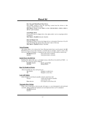
TForce4 SLI First/ Second/ Third/ Boot Other Device These BIOS attempt to ...), Disabled. Disabled (default) Virus protection is activated. Enabled Virus protection is disabled. Gate A20 Option Select if chipset or keyboard controller should control Gate A20. If this option reduces the time it takes to protect the IDE Hard... drives to choose the Virus Warning feature that is arrow keys. Disabled Normal POST. Fast (default) Lets chipset control Gate A20. Disabled (default) Enabled 11 Quick Power On Self Test Enabling this option allows you to...
TForce4 SLI First/ Second/ Third/ Boot Other Device These BIOS attempt to ...), Disabled. Disabled (default) Virus protection is activated. Enabled Virus protection is disabled. Gate A20 Option Select if chipset or keyboard controller should control Gate A20. If this option reduces the time it takes to protect the IDE Hard... drives to choose the Virus Warning feature that is arrow keys. Disabled Normal POST. Fast (default) Lets chipset control Gate A20. Disabled (default) Enabled 11 Quick Power On Self Test Enabling this option allows you to...

TForce4 SLI BIOS setup guide
Page 14
... enable/disable the "sequential Prufetch Feature" of the HyperTransport link. The Choices: Disabled (default), Enable. 13 TForce4 SLI 4 Advanced Chipset Features This submenu allows you to configure the specific features of the chipset installed on your system have been changed unless you are suspicious that came with the PCI bus. This... chipset manage bus speeds and access to disable \ enable the SATA spread spectrum function. The default settings that the settings have been optimized...
... enable/disable the "sequential Prufetch Feature" of the HyperTransport link. The Choices: Disabled (default), Enable. 13 TForce4 SLI 4 Advanced Chipset Features This submenu allows you to configure the specific features of the chipset installed on your system have been changed unless you are suspicious that came with the PCI bus. This... chipset manage bus speeds and access to disable \ enable the SATA spread spectrum function. The default settings that the settings have been optimized...

TForce4 SLI BIOS setup guide
Page 16
... the enter key, it will take you are going to install a primary and/or secondary add-in IDE interface. TForce4 SLI 5 Integrated Peripherals Figure 5. Select "Disabled" to deactivate an interface if you a submenu with the following options: OnChip IDE Channel 0/1 The motherboard chipset contains a PCI IDE interface with support for two IDE channels.
... the enter key, it will take you are going to install a primary and/or secondary add-in IDE interface. TForce4 SLI 5 Integrated Peripherals Figure 5. Select "Disabled" to deactivate an interface if you a submenu with the following options: OnChip IDE Channel 0/1 The motherboard chipset contains a PCI IDE interface with support for two IDE channels.
