Setup Manual
Page 4
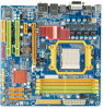
... I /O functionality. SATA Version 2.0 specification compliant. I /O Low Pin Count Interface Environment Control initiatives, H/W Monitor Fan Speed Controller ITE's "Smart Guardian" function Low Pin Count Interface Environment Control initiatives, H/W Monitor Fan Speed Controller ITE's "Smart Guardian" function DIMM Slots x 4 Each DIMM supports 256MB/512MB/ 1GB/2GB/4GB DDR2 DIMM Slots x 4 Each DIMM supports 256MB/512MB/ 1GB/2GB/4GB DDR2 Main Memory Max Memory Capicity 16GB Dual Channel Mode DDR2 memory module Supports DDR2 533 / 667 / 800 Supports DDR2 1066 (by AM2+ CPU) Registered DIMM...
... I /O functionality. SATA Version 2.0 specification compliant. I /O Low Pin Count Interface Environment Control initiatives, H/W Monitor Fan Speed Controller ITE's "Smart Guardian" function Low Pin Count Interface Environment Control initiatives, H/W Monitor Fan Speed Controller ITE's "Smart Guardian" function DIMM Slots x 4 Each DIMM supports 256MB/512MB/ 1GB/2GB/4GB DDR2 DIMM Slots x 4 Each DIMM supports 256MB/512MB/ 1GB/2GB/4GB DDR2 Main Memory Max Memory Capicity 16GB Dual Channel Mode DDR2 memory module Supports DDR2 533 / 667 / 800 Supports DDR2 1066 (by AM2+ CPU) Registered DIMM...

Setup Manual
Page 5
...x1 CPU Fan header x1 System Fan header x2 System Fan header x2 CMOS clear header x1 CMOS clear header x1 USB connector x3 USB connector x3 Serial port Connector x1 Serial port Connector x1 Power Connector (24pin) x1 Power Connector (24pin) x1 Power Connector (4pin) x1 Power Connector (4pin) x1 PS/2 Keyboard x1 PS/2 Keyboard x1 PS/2 Mouse x1 PS/2 Mouse x1 HDMI port x1 HDMI port x1 Back Panel VGA port x1 VGA port x1 I/O DVI-D port x1 DVI-D port x1 LAN port x1 LAN port x1 USB Port x4 USB Port x4 Audio Jack x6 Audio Jack x6 Board Size 244...
...x1 CPU Fan header x1 System Fan header x2 System Fan header x2 CMOS clear header x1 CMOS clear header x1 USB connector x3 USB connector x3 Serial port Connector x1 Serial port Connector x1 Power Connector (24pin) x1 Power Connector (24pin) x1 Power Connector (4pin) x1 Power Connector (4pin) x1 PS/2 Keyboard x1 PS/2 Keyboard x1 PS/2 Mouse x1 PS/2 Mouse x1 HDMI port x1 HDMI port x1 Back Panel VGA port x1 VGA port x1 I/O DVI-D port x1 DVI-D port x1 LAN port x1 LAN port x1 USB Port x4 USB Port x4 Audio Jack x6 Audio Jack x6 Board Size 244...

Setup Manual
Page 13
The IDE connector can connect a master and a slave drive, so you can connect up to two drives. 40 39 2 1 11 TA790GX XE/TA790GX M2+/TA790GXB M2+ 2.4 CONNECTORS AND SLOTS FDD1: Floppy Disk Connector The motherboard provides a standard floppy disk connector that provides PIO Mode 0~4, Bus Master, and Ultra DMA 33/66/100/133 functionality. This connector supports the provided floppy drive ribbon cables. 2 34 1 33 IDE1: IDE/ATAPI Connector The motherboard has a 32-bit Enhanced IDE Controller that supports 360K, 720K, 1.2M, 1.44M and 2.88M floppy disk types.
The IDE connector can connect a master and a slave drive, so you can connect up to two drives. 40 39 2 1 11 TA790GX XE/TA790GX M2+/TA790GXB M2+ 2.4 CONNECTORS AND SLOTS FDD1: Floppy Disk Connector The motherboard provides a standard floppy disk connector that provides PIO Mode 0~4, Bus Master, and Ultra DMA 33/66/100/133 functionality. This connector supports the provided floppy drive ribbon cables. 2 34 1 33 IDE1: IDE/ATAPI Connector The motherboard has a 32-bit Enhanced IDE Controller that supports 360K, 720K, 1.2M, 1.44M and 2.88M floppy disk types.
Setup Manual
Page 27
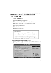
TA790GX XE/TA790GX M2+/TA790GXB M2+ CHAPTER 6: T-SERIES BIOS & SOFTWARE 6.1 T-SERIES BIOS T-Series BIOS Features Overclocking Navigator Engine (O.N.E.) Memory Integration Test (M.I.T., under Overclock Navigator Engine) BIO-Flasher: Update BIOS file from this manual is being continuously updated. Change Option F1 General Help F10 Save and Exit ESC Exit vxx.xx (C)Copyright 1985-200x, American Megatrends, Inc. 25 For better system performance, the BIOS firmware is for both Elite and Casual overclockers. Main Advanced BIOS SETUP UTILITY PCIPnP Boot Chipset T-Series Exit T-...
TA790GX XE/TA790GX M2+/TA790GXB M2+ CHAPTER 6: T-SERIES BIOS & SOFTWARE 6.1 T-SERIES BIOS T-Series BIOS Features Overclocking Navigator Engine (O.N.E.) Memory Integration Test (M.I.T., under Overclock Navigator Engine) BIO-Flasher: Update BIOS file from this manual is being continuously updated. Change Option F1 General Help F10 Save and Exit ESC Exit vxx.xx (C)Copyright 1985-200x, American Megatrends, Inc. 25 For better system performance, the BIOS firmware is for both Elite and Casual overclockers. Main Advanced BIOS SETUP UTILITY PCIPnP Boot Chipset T-Series Exit T-...

Setup Manual
Page 31
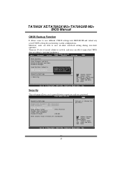
... model. Step 3 When the process is under this test. B. MIT allows users to test memory compatibilities, and no extra devices or software are needed. OverClock Navigator [Normal] =========== Automate OverClock System =========== Auto OverClock System [V6-Tech Engine] Manual OverClock System CPU Frequency [200] > CPU FID/VID Control > Voltage Configuration > DRAM Timing Configuration > Hyper Transport Configuration > Memory Configuration > EC Configuration GFX Engine Clock Override [Disabled] Integrated Memory Test [Disabled] Options Enabled Disabled Select Screen...
... model. Step 3 When the process is under this test. B. MIT allows users to test memory compatibilities, and no extra devices or software are needed. OverClock Navigator [Normal] =========== Automate OverClock System =========== Auto OverClock System [V6-Tech Engine] Manual OverClock System CPU Frequency [200] > CPU FID/VID Control > Voltage Configuration > DRAM Timing Configuration > Hyper Transport Configuration > Memory Configuration > EC Configuration GFX Engine Clock Override [Disabled] Integrated Memory Test [Disabled] Options Enabled Disabled Select Screen...

Setup Manual
Page 33
... BIOS SETUP UTILITY Smart Fan Configuration CPU Smart Fan Smart Fan Calibration Control Mode Fan Ctrl OFF(oC) Fan Ctrl On(oC) Fan Ctrl Start value Fan Ctrl Sensitive [Disabled] When you choice [Auto] ,[3Pin] or [4Pin], please run the calibration to control CPU/System Temperature vs. Self Recovery System (S.R.S.) This function can prevent system hang-up due to inappropriate overclock actions. However, it can 't be seen under "Smart Fan Configuration" in the default BIOS setting, and all overclock settings will be re-configured...
... BIOS SETUP UTILITY Smart Fan Configuration CPU Smart Fan Smart Fan Calibration Control Mode Fan Ctrl OFF(oC) Fan Ctrl On(oC) Fan Ctrl Start value Fan Ctrl Sensitive [Disabled] When you choice [Auto] ,[3Pin] or [4Pin], please run the calibration to control CPU/System Temperature vs. Self Recovery System (S.R.S.) This function can prevent system hang-up due to inappropriate overclock actions. However, it can 't be seen under "Smart Fan Configuration" in the default BIOS setting, and all overclock settings will be re-configured...

Setup Manual
Page 34
... Discard Changes Load Optimal Defaults CMOS Backup Function Security Settings > Security BIOS SETUP UTILITY Boot Chipset T-Series Exit CMOS Backup Func CMOS Data Reload CMOS Data Save Select Screen Select Item EnterGo to the set value, the CPU/System fan will turn off. There are 10 sets of CPU/System fan. Fan Ctrl On(℃) The CPU/System fan starts to this item and then the BIOS will raise the speed of record addresses in total, and users are...
... Discard Changes Load Optimal Defaults CMOS Backup Function Security Settings > Security BIOS SETUP UTILITY Boot Chipset T-Series Exit CMOS Backup Func CMOS Data Reload CMOS Data Save Select Screen Select Item EnterGo to the set value, the CPU/System fan will turn off. There are 10 sets of CPU/System fan. Fan Ctrl On(℃) The CPU/System fan starts to this item and then the BIOS will raise the speed of record addresses in total, and users are...

Setup Manual
Page 44
... BIOS setup, use the Load Optimized Defaults function and then Save and Exit Setup to proceed. Download completes; The programing procedure may be changed without notice. the utility will ask you to enter BIOS setup. Click Yes to exit BIOS setup. While the system boots up and the full screen logo shows, press key to program (update) the BIOS. Motherboard Manual (for your BIOS has been the latest version. Online Update is being continuously updated...
... BIOS setup, use the Load Optimized Defaults function and then Save and Exit Setup to proceed. Download completes; The programing procedure may be changed without notice. the utility will ask you to enter BIOS setup. Click Yes to exit BIOS setup. While the system boots up and the full screen logo shows, press key to program (update) the BIOS. Motherboard Manual (for your BIOS has been the latest version. Online Update is being continuously updated...

Setup Manual
Page 47
... are used for recovery 4 Flash Programming successful 5 File read error 7 No Flash EPROM detected 10 Flash Erase error 11 Flash Program error 12 "AMIBOOT.ROM" file size error 13 BIOS ROM image mismatch (file layout does not match image present in flash device) POST BIOS Beep Codes Number of Beeps Description 1 Memory refresh timer error 3 Base memory read/write test error 6 Keyboard controller BAT command failed 7 General exception error (processor exception interrupt error) 8 Display memory error (system video adapter) Troubleshooting POST BIOS Beep Codes Number...
... are used for recovery 4 Flash Programming successful 5 File read error 7 No Flash EPROM detected 10 Flash Erase error 11 Flash Program error 12 "AMIBOOT.ROM" file size error 13 BIOS ROM image mismatch (file layout does not match image present in flash device) POST BIOS Beep Codes Number of Beeps Description 1 Memory refresh timer error 3 Base memory read/write test error 6 Keyboard controller BAT command failed 7 General exception error (processor exception interrupt error) 8 Display memory error (system video adapter) Troubleshooting POST BIOS Beep Codes Number...

Bios Manual
Page 6
... (C)Copyright 1985-200x, American Megatrends, Inc. SATA 1/2/3/4/5/6 Dev ice Main BIOS SETUP UTILITY Primary IDE Master Device : Type [Auto] LBA/Large Mode [Auto] Block (Multi-Sector Transfer)[Auto] PIO Mode [Auto] DMA Mode [Auto] S.M.A.R.T [Auto] 32Bit Data Transfer [Enabled] Select the type of the sub-menu. TA790GX XE/TA790GX M2+/TA790GXB M2+ BIOS Manual Primary IDE Master/Slav e ; Select Screen Select Item +- Type Select the type of the IDE/SAT A drive. Options: Auto (Default) / Disabled S.M.A.R.T Set the Smart Monitoring, Analysis, and Reporting T echnology.
... (C)Copyright 1985-200x, American Megatrends, Inc. SATA 1/2/3/4/5/6 Dev ice Main BIOS SETUP UTILITY Primary IDE Master Device : Type [Auto] LBA/Large Mode [Auto] Block (Multi-Sector Transfer)[Auto] PIO Mode [Auto] DMA Mode [Auto] S.M.A.R.T [Auto] 32Bit Data Transfer [Enabled] Select the type of the sub-menu. TA790GX XE/TA790GX M2+/TA790GXB M2+ BIOS Manual Primary IDE Master/Slav e ; Select Screen Select Item +- Type Select the type of the IDE/SAT A drive. Options: Auto (Default) / Disabled S.M.A.R.T Set the Smart Monitoring, Analysis, and Reporting T echnology.

Bios Manual
Page 9
Options: Enabled (Default) / Disabled SuperIO Configuration Advan ced BIOS SETU P U TILITY Configure ITE8 718 Super IO Chipse t Onboard Floppy Controller Serial Port1 A ddress Parallel Port Address Parallel Por t Mode Parallel Por t IRQ Keyboard Power On Mouse PowerOn Restore on the system board and you installed another FDC or the system uses no floppy drive, select disabled in this field. Onboard Floppy Controller Select enabled if your system resou rce into several parts, thus enhance the performance when...
Options: Enabled (Default) / Disabled SuperIO Configuration Advan ced BIOS SETU P U TILITY Configure ITE8 718 Super IO Chipse t Onboard Floppy Controller Serial Port1 A ddress Parallel Port Address Parallel Por t Mode Parallel Por t IRQ Keyboard Power On Mouse PowerOn Restore on the system board and you installed another FDC or the system uses no floppy drive, select disabled in this field. Onboard Floppy Controller Select enabled if your system resou rce into several parts, thus enhance the performance when...

Bios Manual
Page 12
... +5.00V +12.0V DDR Voltage HT Voltage 5VSB S elect Screen S elect Item +- Options: Enabled (Default) / Disabled Shutdow n Temperature T his item shows the system temperature, fan speed, and voltage information. This item is only effective under Smart Fan Function mode. Advan ced BIOS SETU P U TILITY Hardware Healt h Configuration H/W Health Fun ction Shutdown Tempe rature [Ena bled] [Dis abled] SYS Temperatur e CPU Temperatur e CPU FAN Speed( JCFAN1) CHIP FAN Speed (JNFAN1) SYS FAN Speed( JSFAN1) Enables Hardware Health Monitoring Device. Options: Disabled (Default) / 60℃/140...
... +5.00V +12.0V DDR Voltage HT Voltage 5VSB S elect Screen S elect Item +- Options: Enabled (Default) / Disabled Shutdow n Temperature T his item shows the system temperature, fan speed, and voltage information. This item is only effective under Smart Fan Function mode. Advan ced BIOS SETU P U TILITY Hardware Healt h Configuration H/W Health Fun ction Shutdown Tempe rature [Ena bled] [Dis abled] SYS Temperatur e CPU Temperatur e CPU FAN Speed( JCFAN1) CHIP FAN Speed (JNFAN1) SYS FAN Speed( JSFAN1) Enables Hardware Health Monitoring Device. Options: Disabled (Default) / 60℃/140...

Bios Manual
Page 13
... abled] Power On by PC IE/Onboard LAN [Dis abled] Wake up by PCI [Dis abled] Select the ACPI state used to enable or disable the motherboard's APIC (Advan ced Programmable Interrupt Controller). Options: Enabled (Default) / Disabled 12 T he item allows you to an OEMB table in the Root System Description T able (RSDT ) table. Options: ACPI v1.0 (Default) / ACPI v2.0 ACPI APIC support T his item is used for System Suspend. Suspend mode T he...
... abled] Power On by PC IE/Onboard LAN [Dis abled] Wake up by PCI [Dis abled] Select the ACPI state used to enable or disable the motherboard's APIC (Advan ced Programmable Interrupt Controller). Options: Enabled (Default) / Disabled 12 T he item allows you to an OEMB table in the Root System Description T able (RSDT ) table. Options: ACPI v1.0 (Default) / ACPI v2.0 ACPI APIC support T his item is used for System Suspend. Suspend mode T he...

Bios Manual
Page 26
Options: Enabled (Default) / Disabled * SP=SIDEPORT. Options: Auto (Default) / Disabled FB Location T his item allows you to control the northbridge HD azalia (HDMI audio) function. PCI Express Configuration BIOS SETU P U TILITY Chipset PCI Express Co nfiguration GFX Dual Slot Configuration [Dis abled] GPP Slots Powe r Limit, W [25 ] > Port #02 Fea tures > Port #04 Fea tures > Port #05 Fea tures > Port #06 Fea tures > Port #07 Fea tures > Port #09 Fea tures > Port #10 Fea tures > NB-SB Port F eatures Options Auto Enabled Disabled S elect Screen S elect Item...
Options: Enabled (Default) / Disabled * SP=SIDEPORT. Options: Auto (Default) / Disabled FB Location T his item allows you to control the northbridge HD azalia (HDMI audio) function. PCI Express Configuration BIOS SETU P U TILITY Chipset PCI Express Co nfiguration GFX Dual Slot Configuration [Dis abled] GPP Slots Powe r Limit, W [25 ] > Port #02 Fea tures > Port #04 Fea tures > Port #05 Fea tures > Port #06 Fea tures > Port #07 Fea tures > Port #09 Fea tures > Port #10 Fea tures > NB-SB Port F eatures Options Auto Enabled Disabled S elect Screen S elect Item...

Bios Manual
Page 30
MAC ID Information T his option allows you to control the onboard LAN controller. Options: Enable (Default) / Disable Realtek Option ROM T his item allows you to enable or disable the Onboard LAN Boot ROM. TA790GX XE/TA790GX M2+/TA790GXB M2+ BIOS Manual OnBoard Peripherals Configuration BIOS SETU P U TILITY Chipset MAC ID Informa tion Realtek PCIE N IC Realtek Optio n ROM [Ena ble] [Dis abled] Enable/Disable Onboard RTL8111C PCIE Network Controller S elect Screen S elect Item +- Realtek PCIE NIC T his area shows the MAC ID. C hange Option F1 G eneral Help F10...
MAC ID Information T his option allows you to control the onboard LAN controller. Options: Enable (Default) / Disable Realtek Option ROM T his item allows you to enable or disable the Onboard LAN Boot ROM. TA790GX XE/TA790GX M2+/TA790GXB M2+ BIOS Manual OnBoard Peripherals Configuration BIOS SETU P U TILITY Chipset MAC ID Informa tion Realtek PCIE N IC Realtek Optio n ROM [Ena ble] [Dis abled] Enable/Disable Onboard RTL8111C PCIE Network Controller S elect Screen S elect Item +- Realtek PCIE NIC T his area shows the MAC ID. C hange Option F1 G eneral Help F10...

Bios Manual
Page 38
... allows you to control the DDR2 dual-channel function. Bank Interleaving Bank Interleaving is an advanced chipset technique used to more than one piece ofmemory. Options: Auto (Default) Channel Interleaving T his item determines whether the BIOS should actively reduce EMI (Electromagn etic Interference) and reduce power consumption by allowing simultaneous access to improve memory perform ance. Options: Disabled (Default) / Enabled 37 TA790GX XE/TA790GX M2+/TA790GXB M2+ BIOS Manual Memory Configuration Memory Configu ration Bank...
... allows you to control the DDR2 dual-channel function. Bank Interleaving Bank Interleaving is an advanced chipset technique used to more than one piece ofmemory. Options: Auto (Default) Channel Interleaving T his item determines whether the BIOS should actively reduce EMI (Electromagn etic Interference) and reduce power consumption by allowing simultaneous access to improve memory perform ance. Options: Disabled (Default) / Enabled 37 TA790GX XE/TA790GX M2+/TA790GXB M2+ BIOS Manual Memory Configuration Memory Configu ration Bank...
Bios Manual
Page 44
... Pas sword :Not Installe d User Password :Not Installe d Change Supervi sor Password User Access Le vel Change User Pa ssword Clear User Pas sword Password Check [Ful l Access] [Set up] Boot Sector Vi rus Protection [Dis abled] Install or Change the password. Main Advan ced BIOS SETU P U TILITY PCIPnP Boot Chipset T-Series Exit Exit Options Save Changes a nd Exit Discard Change s and Exit Discard Change s Load Optimal D efaults CMOS Backup Fu nction CMOS Backup Func CMOS Data Reload CMOS Data Save Security Setti...
... Pas sword :Not Installe d User Password :Not Installe d Change Supervi sor Password User Access Le vel Change User Pa ssword Clear User Pas sword Password Check [Ful l Access] [Set up] Boot Sector Vi rus Protection [Dis abled] Install or Change the password. Main Advan ced BIOS SETU P U TILITY PCIPnP Boot Chipset T-Series Exit Exit Options Save Changes a nd Exit Discard Change s and Exit Discard Change s Load Optimal D efaults CMOS Backup Fu nction CMOS Backup Func CMOS Data Reload CMOS Data Save Security Setti...
Update Manual
Page 1
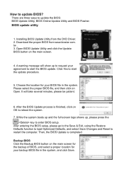
... the DVD Driver. 2. Click Yes to enter BIOS setup. While the system boots up and the full screen logo shows up to request your agreement to update the BIOS: BIOS Update Utility, BIOS Online Update Utility and BIOS Flasher. How to restart the computer. BIOS update utility 1. Installing BIOS Update Utility from www.biostar.com. After entering the BIOS setup, please go to the Save & Exit, using the Restore Defaults function to load Optimized Defaults, and select Save Changes and Reset to update BIOS? Open BIOS Update Utility...
... the DVD Driver. 2. Click Yes to enter BIOS setup. While the system boots up and the full screen logo shows up to request your agreement to update the BIOS: BIOS Update Utility, BIOS Online Update Utility and BIOS Flasher. How to restart the computer. BIOS update utility 1. Installing BIOS Update Utility from www.biostar.com. After entering the BIOS setup, please go to the Save & Exit, using the Restore Defaults function to load Optimized Defaults, and select Save Changes and Reset to update BIOS? Open BIOS Update Utility...
Update Manual
Page 2
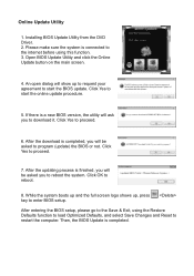
... using the Restore Defaults function to load Optimized Defaults, and select Save Changes and Reset to restart the computer. If there is finished, you will ask you to start the BIOS update. Open BIOS Update Utility and click the Online Update button on the main screen. 4. Click Yes to download it. Installing BIOS Update Utility from the DVD Driver. 2. After the updating process is a new BIOS version, the utility will be asked you will show up , press key...
... using the Restore Defaults function to load Optimized Defaults, and select Save Changes and Reset to restart the computer. If there is finished, you will ask you to start the BIOS update. Open BIOS Update Utility and click the Online Update button on the main screen. 4. Click Yes to download it. Installing BIOS Update Utility from the DVD Driver. 2. After the updating process is a new BIOS version, the utility will be asked you will show up , press key...
Update Manual
Page 3
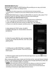
After entering the POST screen, the BIOSFLASHER utility pops out. Choose [fs0] to search for the motherboard. 2. Select the proper BIOS file, and a message asking if you are subject to be slightly different from this manual. After entering the BIOS setup, please go to the Save & Exit, using the Restore Defaults function to load Optimized Defaults, and select Save Changes and Reset to system boot failure. Then, the BIOS Update is being...
After entering the POST screen, the BIOSFLASHER utility pops out. Choose [fs0] to search for the motherboard. 2. Select the proper BIOS file, and a message asking if you are subject to be slightly different from this manual. After entering the BIOS setup, please go to the Save & Exit, using the Restore Defaults function to load Optimized Defaults, and select Save Changes and Reset to system boot failure. Then, the BIOS Update is being...


