Biostar P4TGE Support and Manuals
Get Help and Manuals for this Biostar item

View All Support Options Below
Free Biostar P4TGE manuals!
Problems with Biostar P4TGE?
Ask a Question
Free Biostar P4TGE manuals!
Problems with Biostar P4TGE?
Ask a Question
Popular Biostar P4TGE Manual Pages
P4TGE user's manual - Page 1

... reasonable protection against harmful interference in a residential installation. These limits are trademarks of this publication, in part or in whole is subject to the contents here of and specially disclaims any implied warranties of merchantability or fitness for any mistakes found to comply with the instructions, may cause harmful interference to notify any...
P4TGE user's manual - Page 3

... modes. MMootthheerrbbooaarrdd DDeessccrriippttiioonn
English
P4TGE Features
Use Intel 845GE/ ICH4 Chipset, Winbond W83627, 1394A Chip, SATA/ RAID Chip (Optional). Supports Intel Pentium 4 processor with PC ATX form factor specifications. Supports five 32-bit PCI Bus slots, one AGP Slot, and one VGA port, a parallel port, a PS/2 mouse port, a PS/2 keyboard port, audio ports, USB ports and...
P4TGE user's manual - Page 4

...can transfer data with rear out . Provides advance chained packet commands for AC3® 5.1CH purpose. Supports ATA proprosal PIO Mode 0, 1, 2, 3, 4, Ultra DMA Mode 0, 1, 2, 3, 4, 5, 6. Supports 4.1/5.1 speakers, C3DX positional audio in 2 channels SATA PHY, which satisfy ATA 133 specification. Built in 4/ 6 CH speaker mode. Automatically detects whether or not the cable is capable of...
P4TGE user's manual - Page 6

...
9
1 JUSBV3_4
ICH4
IDE2 IDE1 JSFAN1 1
1 JCDIN1
PCI3
PCI4 JSPDIF_OUT 1
PCI SLOT PCI SLOT
Hardware Audio
PCI5
PCI SLOT
CNR1
CNR SLOT
JWOL1 2 10 1
19 J1394A1
2 10 J1394B1
19
Winbond I/O
JCMOS1 ...2 JPANEL1 24
1
23
4
Floppy Disk Conn. MMootthheerrbbooaarrdd DDeessccrriippttiioonn
Layout of P4TGE
JKBMS1 KB &
Mouse
JUSBLAN1
USB & LAN 1
JCOM1
1
JKBV1 JUSBV1
JATXPWR2 CPU1
Socket 478
...
P4TGE user's manual - Page 7

Pull the lever sideways away from the socket then raise the lever up to complete the installation. Locate Pin A in the socket and lock for the white dot or cut edge then insert ...fan's power port into the JCFAN1, then to 90-degree angle.
2.
MMootthheerrbbooaarrdd DDeessccrriippttiioonn
CPU Installation
CPU
1. Match Pin A with the white dot/cut edge in the CPU. Press the lever down.
P4TGE user's manual - Page 8

If use FSB 400MHz CPU, the memory run only at DDR200/266. How to install a DIMM Module
1.
Insert the DIMM memory modules into the socket at a 90... and the DIMM memory module has an "Asymmetrical notch", so the DIMM memory module can only fit into the place.
3. Push the tabs out. MMootthheerrbbooaarrdd DDeessccrriippttiioonn
DDR DIMM Modules: DDR1-2
Supports DDR200/266/333 unregistered...
P4TGE user's manual - Page 9
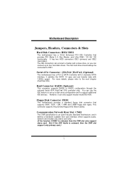
... ATA Connector: (JSATA1/ JSATA2) (Optional)
The motherboard has a PCI to the next chapter (FastTrak 376).
This connector supports the provided floppy drive ribbon cables. Communication Network Riser Slot: CNR1
The CNR specification is an open Industry Standard Architecture, and it defines a hardware scalable riser card interface, which supports audio, network and modem only (slave card...
P4TGE user's manual - Page 10
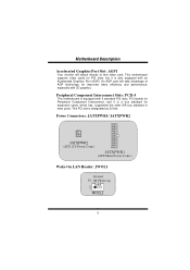
This PCI slot is also equipped with 5 standard PCI slots. This motherboard supports video cards for PCI slots, but it is equipped with an Accelerated Graphics Port (AGP). Peripheral Component Interconnect Slots: PCI1-5
This motherboard is a bus standard for expansion cards, which has, supplanted the older ISA bus standard in most ports. Power Connectors: JATXPWR1...
P4TGE user's manual - Page 12
...
9 KEY 10 NA
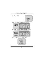
Serial ATA Connector: JSATA1/ JSATA2 (Optional)
14 7
23 56
JSATA1/2
Pin Assignment Pin Assignment 1 Ground 2 TX+
3 TX- 4 Ground 5 RX- 6 RX+ 7 Ground
Digital Audio Connector: JSPDIF_OUT SPDIF_Out GND 5V 1
JSPDIF_OUT
10
P4TGE user's manual - Page 13

... Header)
22 1
14 13 JAUDIO1
Pin
Assignment Pin Assignment
1
Mic In
2
Ground
3
Mic Power
4
Audio Power
5
RT Line Out
6
RT Line Out
7
Reserved
8
Key
9
LFT Line Out
10 LFT Line Out
11
RT Line In
12 RT Line In...
13 LFT Line In
14 LFT Line In
Pin 5, 9, 11, 13 are routed from Front Panel Audio Out.
11 Pin 6, 10, 12, 14 are routed to Front Panel...
P4TGE user's manual - Page 14

... MMootthheerrbbooaarrdd DDeessccrriippttiioonn
Front Panel Audio Connector/ Jumper Block
Jumper Setting
1 3 5 7
246
Pin 5 and 6 Pin 9 and 10
9 10 Pin11 and 12
11 12 Pin13 and 14
13 14
Configuration
Audio line out signals are routed to the back panel audio line out connector.
12
3 5
4 6
No jumpers
7 9
10
installed
11 12
13 14
Audio line out and mic...
P4TGE user's manual - Page 15
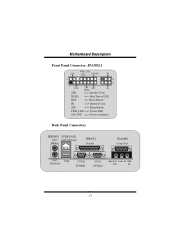
HLED ==> Hard Driver LED
RST
==> Reset Button
IR
==> Infrared Conn.
MMootthheerrbbooaarrdd DDeessccrriippttiioonn
Front Panel Connector: JPANEL1
PWR_LED
SLP
(+) (+) (-) ON/OFF
IR
2
24
1
23
SPK
SPK
(+) (-)
RST
IR
HLED
==> ...
P4TGE user's manual - Page 28

... MMootthheerrbbooaarrdd DDeessccrriippttiioonn
Front Panel Audio Connector/ Jumper Block
Jumper Setting
1 3 5 7
246
Pin 5 and 6 Pin 9 and 10
9 10 Pin11 and 12
11 12 Pin13 and 14
13 14
Configuration
Audio line out signals are routed to the back panel audio line out connector.
12
3 5 7 9
46
No jumpers
10 installed
11 12
13 14
Audio line out and...
P4TGE user's manual - Page 31

... SETUP program and select correct drive
types. check the drive type in
illuminate, fan inside on. Make sure
"CMOS Failure." PROBABLE CAUSE
SOLUTION
Cannot boot system after installing second hard * Set...
Trouble Shooting
PROBABLE CAUSE
SOLUTION
No power to disk
be booted from CD-ROM drive. Keyboard lights are on, * Using even pressure on
*
Replace
cable
* Contact technical support...
Biostar P4TGE Reviews
We have not received any reviews for Biostar yet.