
M7VIT Bravo user's manual
Page 2
TTaabbllee ooff tthhee CCoonntteennttss LAYOUT OF M7VIT BRAVO 1 COMPONENT INDEX 2 M7VIT BRAVO SYSTEM STRUCTURE 3 ENGLISH 4 M7VIT Bravo Features 4 Package contents...5 How to set up Jumper 6 CPU Installation...6 DDR DIMM Modules: DDR1, DDR2 7 Installing DDR Module 7 Jumpers, Headers, Connectors & Slots 8 WARPSPEEDER 13 Introduction ...13 System Requirement 13 Installation ...14 Usage ...15 TROUBLE SHOOTING 23 ii
TTaabbllee ooff tthhee CCoonntteennttss LAYOUT OF M7VIT BRAVO 1 COMPONENT INDEX 2 M7VIT BRAVO SYSTEM STRUCTURE 3 ENGLISH 4 M7VIT Bravo Features 4 Package contents...5 How to set up Jumper 6 CPU Installation...6 DDR DIMM Modules: DDR1, DDR2 7 Installing DDR Module 7 Jumpers, Headers, Connectors & Slots 8 WARPSPEEDER 13 Introduction ...13 System Requirement 13 Installation ...14 Usage ...15 TROUBLE SHOOTING 23 ii
M7VIT Bravo user's manual
Page 3
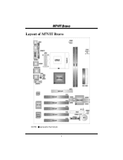
MM77VVIITT BBrraavvoo Layout of M7VIT Bravo NOTE: ●represents the first pin. 1
MM77VVIITT BBrraavvoo Layout of M7VIT Bravo NOTE: ●represents the first pin. 1
M7VIT Bravo user's manual
Page 4
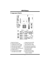
Back Panel Connector J. PCI BUS Slots:PCI 1-5 P. ATX Power Connector:ATX1 K. Front Audio Header:JAUDIO1 N. Case Open Connector:JCI1 C. Serial ATA Connectors:JSATA1-2* E. Front USB Header:JUSB2/(JUSB3)* F. IDE Connectors:IDE1-2 G. Front Panel Connector:JPANEL1 Q. CPU Fan Connector:JCFAN1 * stands for "Optional." 2 MM77VVIITT BBrraavvoo Component Index A. System FAN Header:JSFAN1 D. Accelerated Graphics Port Slot:AGP1 O. CD-ROM Audio-In Header:JCDIN1 L. Digital Audio Connector:JSPDIF1 M. Frequency Selection:JCLK1 I. DDR Modules:DDR1-2 H. Clear CMOS ...
Back Panel Connector J. PCI BUS Slots:PCI 1-5 P. ATX Power Connector:ATX1 K. Front Audio Header:JAUDIO1 N. Case Open Connector:JCI1 C. Serial ATA Connectors:JSATA1-2* E. Front USB Header:JUSB2/(JUSB3)* F. IDE Connectors:IDE1-2 G. Front Panel Connector:JPANEL1 Q. CPU Fan Connector:JCFAN1 * stands for "Optional." 2 MM77VVIITT BBrraavvoo Component Index A. System FAN Header:JSFAN1 D. Accelerated Graphics Port Slot:AGP1 O. CD-ROM Audio-In Header:JCDIN1 L. Digital Audio Connector:JSPDIF1 M. Frequency Selection:JCLK1 I. DDR Modules:DDR1-2 H. Clear CMOS ...
M7VIT Bravo user's manual
Page 6
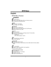
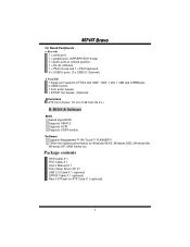
.../100/133 Bus Master Mode. Supports 6 channels. One AGP 4X/8X slot. Main Memory Supports up to 2 DDR devices. On Board IDE Supports four IDE disk drives. LAN PHY: VIA VT6103. Front Side Bus at 200/266/333 MHz. Provides the most commonly used legacy Super I /O Chip: U2 ITE8705F. ITE's "Smart Guardian" function Slots Five 32-bit PCI bus master slots. On Board AC'97 Sound Codec Chip: CMI9761A. Maximum memory size is 2GB. MM77VVIITT BBrraavvoo English M7VIT Bravo Features A. Hardware CPU Provides Socket A. South...
.../100/133 Bus Master Mode. Supports 6 channels. One AGP 4X/8X slot. Main Memory Supports up to 2 DDR devices. On Board IDE Supports four IDE disk drives. LAN PHY: VIA VT6103. Front Side Bus at 200/266/333 MHz. Provides the most commonly used legacy Super I /O Chip: U2 ITE8705F. ITE's "Smart Guardian" function Slots Five 32-bit PCI bus master slots. On Board AC'97 Sound Codec Chip: CMI9761A. Maximum memory size is 2GB. MM77VVIITT BBrraavvoo English M7VIT Bravo Features A. Hardware CPU Provides Socket A. South...
M7VIT Bravo user's manual
Page 7
... Award legal BIOS. Supports ACPI. Supports USB Function. Offers the highest performance for ATX Case X 1 (optional) 5 Supports APM1.2. Rear side 1 x serial port. 1 x parallel port. (SPP/EPP/ECP mode) 1x Audio ports in vertical position. 1 x RJ-45 LAN jack. 1 x PS/2 mouse and 1 x PS/2 keyboard. 4 x USB2.0 ports. (2 x USB2.0: Optional) b. Software Supports Warpspeeder™, 9th Touch™, FLASHER™. Package contents HDD Cable X 1 FDD Cable X 1 User's Manual X 1 Fully Setup Driver CD X 1 USB 2.0 Cable X 1 (optional) S/PDIF Cable X 1 (optional) Rear I/O Panel for Windows...
... Award legal BIOS. Supports ACPI. Supports USB Function. Offers the highest performance for ATX Case X 1 (optional) 5 Supports APM1.2. Rear side 1 x serial port. 1 x parallel port. (SPP/EPP/ECP mode) 1x Audio ports in vertical position. 1 x RJ-45 LAN jack. 1 x PS/2 mouse and 1 x PS/2 keyboard. 4 x USB2.0 ports. (2 x USB2.0: Optional) b. Software Supports Warpspeeder™, 9th Touch™, FLASHER™. Package contents HDD Cable X 1 FDD Cable X 1 User's Manual X 1 Fully Setup Driver CD X 1 USB 2.0 Cable X 1 (optional) S/PDIF Cable X 1 (optional) Rear I/O Panel for Windows...
M7VIT Bravo user's manual
Page 8
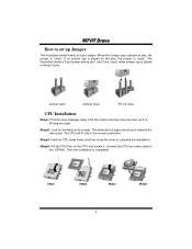
.... Step3: Hold the CPU down firmly, and then close CPU Installation Step1: Pull the lever sideways away from the socket and then raise the lever up to complete the installation. Jumper open ". If no jumper cap is placed on the CPU and buckle it. The CPU will fit only in the correct orientation. Connect the CPU fan power cable to set up Jumper The illustration shows...
.... Step3: Hold the CPU down firmly, and then close CPU Installation Step1: Pull the lever sideways away from the socket and then raise the lever up to complete the installation. Jumper open ". If no jumper cap is placed on the CPU and buckle it. The CPU will fit only in the correct orientation. Connect the CPU fan power cable to set up Jumper The illustration shows...

M7VIT Bravo user's manual
Page 9
... into the slot until the retaining chip snap back in the way that the notch of the DIMM matches the break of the slot. 2. Unlock a DIMM slot by pressing the retaining clips outward. DRAM Type: 64MB/ 128MB/ 256MB/ 512MB/ 1GB DIMM Module (184 pin) DIMM Socket Location DDR Module Total Memory Size (MB) DDR 1 64MB/128MB/256MB/512MB/1GB *1 Max is properly...
... into the slot until the retaining chip snap back in the way that the notch of the DIMM matches the break of the slot. 2. Unlock a DIMM slot by pressing the retaining clips outward. DRAM Type: 64MB/ 128MB/ 256MB/ 512MB/ 1GB DIMM Module (184 pin) DIMM Socket Location DDR Module Total Memory Size (MB) DDR 1 64MB/128MB/256MB/512MB/1GB *1 Max is properly...
M7VIT Bravo user's manual
Page 10
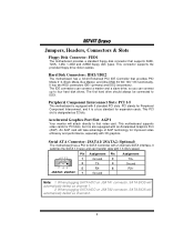
... to four hard disk drives. Serial ATA Connector: JSATA1/ JSATA2 (Optional) The motherboard has a PCI to that video card. This motherboard supports video cards for PCI slots, but it satisfies the SATA 1.0 spec and can connect up to IDE1. Accelerated Graphics Port Slot: AGP1 Your monitor will automatically detect as channel 1. 2. When plugging SATA HDD on JSATA1 connector, SATA BIOS will attach directly to SATA Controller with 2 channels SATA interface, it is a bus standard for improved video efficiency and performance, especially with 1.5 Gb/s speed. 65 3 2 Pin...
... to four hard disk drives. Serial ATA Connector: JSATA1/ JSATA2 (Optional) The motherboard has a PCI to that video card. This motherboard supports video cards for PCI slots, but it satisfies the SATA 1.0 spec and can connect up to IDE1. Accelerated Graphics Port Slot: AGP1 Your monitor will automatically detect as channel 1. 2. When plugging SATA HDD on JSATA1 connector, SATA BIOS will attach directly to SATA Controller with 2 channels SATA interface, it is a bus standard for improved video efficiency and performance, especially with 1.5 Gb/s speed. 65 3 2 Pin...
M7VIT Bravo user's manual
Page 11
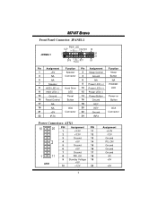
... Front Panel Connector: JPANEL1 JPANEL1 SLP PWR_LED (+) (+)(-) ON/OFF 2 1 SPK (+) (-) HLED RST IR 24 23 IR Pin Assignment 1 +5V 3 NA 5 NA 7 Speaker 9 HDD LED (+) 11 HDD LED (-) 13 Ground 15 Reset Control 17 NA 19 NA 21 +5V 23 IRTX Function Speaker Connector Hard Drive LED Reset Button IrDA Connector Pin Assignment 2 Sleep Control 4 Ground 6 NA 8 Power LED (+) 10 Power LED (+) 12 Power LED (-) 14 Power Button 16 Ground 18 KEY 20 KEY 22 Ground 24 IRRX Function Sleep Button NA POWER LED Power-on Button IrDA Connector Power Connectors...
... Front Panel Connector: JPANEL1 JPANEL1 SLP PWR_LED (+) (+)(-) ON/OFF 2 1 SPK (+) (-) HLED RST IR 24 23 IR Pin Assignment 1 +5V 3 NA 5 NA 7 Speaker 9 HDD LED (+) 11 HDD LED (-) 13 Ground 15 Reset Control 17 NA 19 NA 21 +5V 23 IRTX Function Speaker Connector Hard Drive LED Reset Button IrDA Connector Pin Assignment 2 Sleep Control 4 Ground 6 NA 8 Power LED (+) 10 Power LED (+) 12 Power LED (-) 14 Power Button 16 Ground 18 KEY 20 KEY 22 Ground 24 IRRX Function Sleep Button NA POWER LED Power-on Button IrDA Connector Power Connectors...
M7VIT Bravo user's manual
Page 12
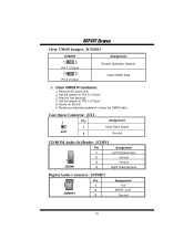
... 13 Pin 1-2 Close 13 Pin 2-3 Close Assignment Normal Operation (default) Clear CMOS Data ※ Clear CMOS Procedures: 1. Set the jumper to "Pin 1-2 Close". 5. Remove AC power line. 2. Power on the AC. 6. Set the jumper to "Pin 2-3 Close". 3. Wait for five seconds. 4. Reset your desired password or clear the CMOS data. Case Open Connector: JCI1 1 Pin 1 JCI1 2 Assignment Case Open Signal Ground CD-ROM Audio-In Header: JCDIN1 Pin Assignment 1 JCDIN1 1 Left Channel Input 2 Ground 3 Ground 4 Right Channel Input Digital Audio Connector: JSPDIF1 1 Pin...
... 13 Pin 1-2 Close 13 Pin 2-3 Close Assignment Normal Operation (default) Clear CMOS Data ※ Clear CMOS Procedures: 1. Set the jumper to "Pin 1-2 Close". 5. Remove AC power line. 2. Power on the AC. 6. Set the jumper to "Pin 2-3 Close". 3. Wait for five seconds. 4. Reset your desired password or clear the CMOS data. Case Open Connector: JCI1 1 Pin 1 JCI1 2 Assignment Case Open Signal Ground CD-ROM Audio-In Header: JCDIN1 Pin Assignment 1 JCDIN1 1 Left Channel Input 2 Ground 3 Ground 4 Right Channel Input Digital Audio Connector: JSPDIF1 1 Pin...
M7VIT Bravo user's manual
Page 13
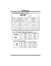
... 4 Audio Power 5 Right Line Out/ Speaker Out 6 Right Line Out/ Speaker Out Right Right 7 Reserved 8 Key 9 Left Line Out/ Speaker Out 10 Left Line Out/ Speaker Out Left Left 11 Right Line In/ Rear Speaker 12 Right Line In/ Rear Speaker Right Right 13 Left Line In/ Rear Speaker Left 14 Left Line In/ Rear Speaker Left Front USB Header: JUSB2/ (JUSB3: Optional) 2 1 10 9 Pin...
... 4 Audio Power 5 Right Line Out/ Speaker Out 6 Right Line Out/ Speaker Out Right Right 7 Reserved 8 Key 9 Left Line Out/ Speaker Out 10 Left Line Out/ Speaker Out Left Left 11 Right Line In/ Rear Speaker 12 Right Line In/ Rear Speaker Right Right 13 Left Line In/ Rear Speaker Left 14 Left Line In/ Rear Speaker Left Front USB Header: JUSB2/ (JUSB3: Optional) 2 1 10 9 Pin...
M7VIT Bravo user's manual
Page 15
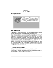
..., on our main panel. The cool Hardware Monitor smartly indicates the temperatures, voltage and CPU fan speed as well as the chipset information. MM77VVIITT BBrraavvoo WarpSpeeder Introduction [ WarpSpeeder™ ], a new powerful control utility, features three user-friendly functions including Overclock Manager, Overvoltage Manager, and Hardware Monitor. If you use Windows XP, you can get detail descriptions about BIOS model and chipsets. In addition, the frequency status of CPU, memory, AGP and PCI along with just...
..., on our main panel. The cool Hardware Monitor smartly indicates the temperatures, voltage and CPU fan speed as well as the chipset information. MM77VVIITT BBrraavvoo WarpSpeeder Introduction [ WarpSpeeder™ ], a new powerful control utility, features three user-friendly functions including Overclock Manager, Overvoltage Manager, and Hardware Monitor. If you use Windows XP, you can get detail descriptions about BIOS model and chipsets. In addition, the frequency status of CPU, memory, AGP and PCI along with just...
M7VIT Bravo user's manual
Page 17
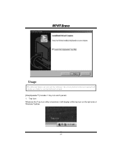
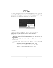
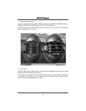
Tray Icon: Whenever the Tray Icon utility is launched, it will change according to your motherboard on the right side of Windows Taskbar. 15 MM77VVIITT BBrraavvoo Usage The following figures are just only for reference, the screen printed in this user manual will display a little tray icon on hand. [WarpSpeeder™] includes 1 tray icon and 5 panels: 1.
Tray Icon: Whenever the Tray Icon utility is launched, it will change according to your motherboard on the right side of Windows Taskbar. 15 MM77VVIITT BBrraavvoo Usage The following figures are just only for reference, the screen printed in this user manual will display a little tray icon on hand. [WarpSpeeder™] includes 1 tray icon and 5 panels: 1.
M7VIT Bravo user's manual
Page 18
... figure; Contains About, Voltage, Overclock, and Hardware Monitor Buttons for conveniently invoking [WarpSpeeder™] Utility. Please refer do the following figure. b. Display the CPU Speed, CPU external clock, Memory clock, AGP clock, and PCI clock information. c. the utility's first window you click the tray icon, [ WarpSpeeder™ ] utility will be invoked. Main Panel contains features as mouse left button in the popup menu has the same function as follows: a. Main Panel If you will...
... figure; Contains About, Voltage, Overclock, and Hardware Monitor Buttons for conveniently invoking [WarpSpeeder™] Utility. Please refer do the following figure. b. Display the CPU Speed, CPU external clock, Memory clock, AGP clock, and PCI clock information. c. the utility's first window you click the tray icon, [ WarpSpeeder™ ] utility will be invoked. Main Panel contains features as mouse left button in the popup menu has the same function as follows: a. Main Panel If you will...
M7VIT Bravo user's manual
Page 19
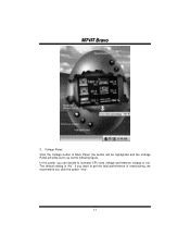
Voltage Panel Click the Voltage button in Main Panel, the button will be highlighted and the Voltage Panel will slide out to increase CPU core voltage and Memory voltage or not. The default setting is "No". If you want to get the best performance of overclocking, we recommend you can decide to up as the following figure. MM77VVIITT BBrraavvoo 3. In this panel, you click the option "Yes". 17
Voltage Panel Click the Voltage button in Main Panel, the button will be highlighted and the Voltage Panel will slide out to increase CPU core voltage and Memory voltage or not. The default setting is "No". If you want to get the best performance of overclocking, we recommend you can decide to up as the following figure. MM77VVIITT BBrraavvoo 3. In this panel, you click the option "Yes". 17
M7VIT Bravo user's manual
Page 21
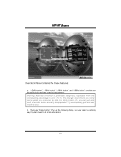
... best result for you overclock by click the Verify button. "-3MHz button", "-1MHz button", "+1MHz button", and "+3MHz button": provide user the ability to do real-time overclock adjustment. b. Let user select a restoring way if system need to do a fail-safe reboot. 19 We strongly recommend you verify every speed you . "Recovery Dialog button": Pop up the following dialog. Warning: Manually overclock is potentially dangerous...
... best result for you overclock by click the Verify button. "-3MHz button", "-1MHz button", "+1MHz button", and "+3MHz button": provide user the ability to do real-time overclock adjustment. b. Let user select a restoring way if system need to do a fail-safe reboot. 19 We strongly recommend you verify every speed you . "Recovery Dialog button": Pop up the following dialog. Warning: Manually overclock is potentially dangerous...
M7VIT Bravo user's manual
Page 22
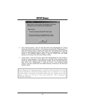
..., invoked in Auto-overclock and Verify, include DirectDraw, Direct3D and DirectShow tests, the DirectX 8.1 or newer runtime library is ok, then the current frequency will do fail-safe reboot by using Watchdog function. After reboot, the [ WarpSpeeder™ ] utility will restore to the hardware default setting or load the verified best and stable frequency according to the Recovery Dialog's setting. If the...
..., invoked in Auto-overclock and Verify, include DirectDraw, Direct3D and DirectShow tests, the DirectX 8.1 or newer runtime library is ok, then the current frequency will do fail-safe reboot by using Watchdog function. After reboot, the [ WarpSpeeder™ ] utility will restore to the hardware default setting or load the verified best and stable frequency according to the Recovery Dialog's setting. If the...
M7VIT Bravo user's manual
Page 23
... will be highlighted and the Hardware Monitor panel will be refreshed every 1 second. 6. You can also get the real-time status information of your system. About Panel Click the About button in Main Panel, the button will slide out to overclocking. In this panel, you can get the mainboard's BIOS model and the Version number of all the chipset that are related to left...
... will be highlighted and the Hardware Monitor panel will be refreshed every 1 second. 6. You can also get the real-time status information of your system. About Panel Click the About button in Main Panel, the button will slide out to overclocking. In this panel, you can get the mainboard's BIOS model and the Version number of all the chipset that are related to left...
M7VIT Bravo user's manual
Page 24
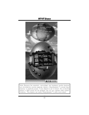
This property can make [ WarpSpeeder™ ] utility more robust. 22 If one chipset is not on board, the correlative button in Main panel will be disabled, but will not interfere other panels' functions. MM77VVIITT BBrraavvoo Note: Because the overclock, overvoltage, and hardware monitor features are controlled by several separate chipset, [ WarpSpeeder™ ] divide these features to separate panels.
This property can make [ WarpSpeeder™ ] utility more robust. 22 If one chipset is not on board, the correlative button in Main panel will be disabled, but will not interfere other panels' functions. MM77VVIITT BBrraavvoo Note: Because the overclock, overvoltage, and hardware monitor features are controlled by several separate chipset, [ WarpSpeeder™ ] divide these features to separate panels.
M7VIT Bravo user's manual
Page 25
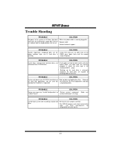
... not boot from hard disk drive, can * Check cable running from hard disk is securely plugged in ; All hard disks are capable of the power indicator lights are securely plugged in illuminate, fan inside power supply does not turn on * Replace cable * Contact technical support PROBABLE SOLUTION System inoperative. PROBABLE SOLUTION System only boots from CD-ROM drive. Make sure "CMOS Failure." Keyboard lights are on, * Using even pressure on . Call drive manufacturers for compatibility with other drives. 23 using backup disks. Make...
... not boot from hard disk drive, can * Check cable running from hard disk is securely plugged in ; All hard disks are capable of the power indicator lights are securely plugged in illuminate, fan inside power supply does not turn on * Replace cable * Contact technical support PROBABLE SOLUTION System inoperative. PROBABLE SOLUTION System only boots from CD-ROM drive. Make sure "CMOS Failure." Keyboard lights are on, * Using even pressure on . Call drive manufacturers for compatibility with other drives. 23 using backup disks. Make...


