
M6VLQ user's manual
Page 3
... Installation 1-8 1.2.1 System Block Diagram 1-8 1.2.2 Layout of Motherboard 1-9 1.2.3 Quick Reference 1-10 1.3 CPU Installation 1-11 1.3.1 CPU Installation Procedure: Socket 370 1-11 1.3.2 CPU Fan Header: JCFAN1 1-12 1.3.3 System Fan Header: JSFAN1 1-12 1.4 RAM Module Installation 1-13 1.4.1 DIMM...1-13 1.4.2 How to install a DIMM Module 1-14 1.5 Slots ...1-15 1.5.1 AMR (Audio Modem Riser) Slot 1-16 (Only support slave card 1-16 1.5.2 PCI (Peripheral Component Interconnect) Slots 1-16 1.5.3 ISA (Industry Standard Architecture) Slot 1-16 1.6 Connectors, Headers & Jumpers...
... Installation 1-8 1.2.1 System Block Diagram 1-8 1.2.2 Layout of Motherboard 1-9 1.2.3 Quick Reference 1-10 1.3 CPU Installation 1-11 1.3.1 CPU Installation Procedure: Socket 370 1-11 1.3.2 CPU Fan Header: JCFAN1 1-12 1.3.3 System Fan Header: JSFAN1 1-12 1.4 RAM Module Installation 1-13 1.4.1 DIMM...1-13 1.4.2 How to install a DIMM Module 1-14 1.5 Slots ...1-15 1.5.1 AMR (Audio Modem Riser) Slot 1-16 (Only support slave card 1-16 1.5.2 PCI (Peripheral Component Interconnect) Slots 1-16 1.5.3 ISA (Industry Standard Architecture) Slot 1-16 1.6 Connectors, Headers & Jumpers...
M6VLQ user's manual
Page 13
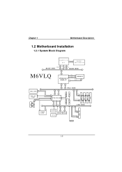
CONN. CNTL A D D R / D ATA SER. CONN. CONN. LAN PCI CONN PCI CONN PCI CONN IDE IDE 1-8 Chapter 1 Motherboard Description 1.2 Motherboard Installation 1.2.1 System Block Diagram SOCKET 370 CPU CLOCK W93194BR-39B CONTROL HOST BUS ADD DATA HOST BUS M6VLQ VT8601T PLE-T CNTL ADDR MEMORY D ATA AMR SLOT AC' 97 CODEC FLASH BIOS PCI BUS USB USB VT82C686B USB USB CNTL A D D R / D ATA ISA BUS IAS CONN KEYBOARD MOUSE FLOPPY LPT.
CONN. CNTL A D D R / D ATA SER. CONN. CONN. LAN PCI CONN PCI CONN PCI CONN IDE IDE 1-8 Chapter 1 Motherboard Description 1.2 Motherboard Installation 1.2.1 System Block Diagram SOCKET 370 CPU CLOCK W93194BR-39B CONTROL HOST BUS ADD DATA HOST BUS M6VLQ VT8601T PLE-T CNTL ADDR MEMORY D ATA AMR SLOT AC' 97 CODEC FLASH BIOS PCI BUS USB USB VT82C686B USB USB CNTL A D D R / D ATA ISA BUS IAS CONN KEYBOARD MOUSE FLOPPY LPT.
M6VLQ user's manual
Page 22
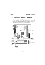
Noticeably, a jumper has two or more pins that can be covered by a plastic jumper cap, allowing you lots of capabilities such as power supply, front panel signal revelation, IDE hard disk connection, floppy disk connection, Wake On LAN function and Front USB connection. Chapter 1 Motherboard Description 1.6 Connectors, Headers & Jumpers The connectors, headers and jumpers introduced below provide you to select different system options. 1 JKBV1 1 JUSBV1 1 JWOL1 1 JWOM1 1 JUSBV2 VT 8601T LAN 8100 VT 82C686B 1 JUSB2 DIMM1 DIMM2 BIOS FDD1 IDE1 IDE2 1 JCMOS1 JPANEL1 1-17
Noticeably, a jumper has two or more pins that can be covered by a plastic jumper cap, allowing you lots of capabilities such as power supply, front panel signal revelation, IDE hard disk connection, floppy disk connection, Wake On LAN function and Front USB connection. Chapter 1 Motherboard Description 1.6 Connectors, Headers & Jumpers The connectors, headers and jumpers introduced below provide you to select different system options. 1 JKBV1 1 JUSBV1 1 JWOL1 1 JWOM1 1 JUSBV2 VT 8601T LAN 8100 VT 82C686B 1 JUSB2 DIMM1 DIMM2 BIOS FDD1 IDE1 IDE2 1 JCMOS1 JPANEL1 1-17
M6VLQ user's manual
Page 24
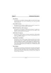
... front panel to the system board. Power Button This connector can be loaded. After the IrDA interface is configured, connectionless data transfer to a momentary SPST switch. APM (Advanced Power Management) must be attached to an infrared sensing device. Power LED Connector This connector can be enabled in use. The LED will power down the monitor and the hard disk when not in the system BIOS and the APM driver must pull the Power Button pin to...
... front panel to the system board. Power Button This connector can be loaded. After the IrDA interface is configured, connectionless data transfer to a momentary SPST switch. APM (Advanced Power Management) must be attached to an infrared sensing device. Power LED Connector This connector can be enabled in use. The LED will power down the monitor and the hard disk when not in the system BIOS and the APM driver must pull the Power Button pin to...
M6VLQ user's manual
Page 25
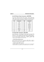
... power connector is similar to IDE1. Using the ATX power supply, function such as Soft Power Off is supported on this controller must configure the second hard drive on -board. Chapter 1 Motherboard Description 1.6.2 ATX 20-pin Power Connector: JATXPWR1 This connector supports the power button on IDE1 to Slave mode by setting the jumper accordingly. • IDE2 (Secondary IDE Connector) The IDE2 controller can connect a Master and a Slave drive. These connectors support the IDE hard disk cable provided. • IDE1 (Primary IDE Connector) The first hard drive should always be set...
... power connector is similar to IDE1. Using the ATX power supply, function such as Soft Power Off is supported on this controller must configure the second hard drive on -board. Chapter 1 Motherboard Description 1.6.2 ATX 20-pin Power Connector: JATXPWR1 This connector supports the power button on IDE1 to Slave mode by setting the jumper accordingly. • IDE2 (Secondary IDE Connector) The IDE2 controller can connect a Master and a Slave drive. These connectors support the IDE hard disk cable provided. • IDE1 (Primary IDE Connector) The first hard drive should always be set...
M6VLQ user's manual
Page 37
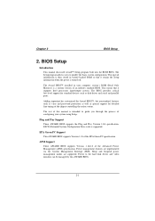
... the chipset controlling the entire system. BIOS Setup Introduction This manual discussed Award™ Setup program built into the ROM BIOS. The Award BIOS™ installed in battery-backed RAM so that it retains the Setup information when the power is supported. Sleep and Suspend power management modes are implemented via the System Management Interrupt (SMI). Plug and Play Support These AWARD BIOS supports the Plug and Play Version 1.0A specification. The Setup program allows users to the hard disk drives and video monitors can...
... the chipset controlling the entire system. BIOS Setup Introduction This manual discussed Award™ Setup program built into the ROM BIOS. The Award BIOS™ installed in battery-backed RAM so that it retains the Setup information when the power is supported. Sleep and Suspend power management modes are implemented via the System Management Interrupt (SMI). Plug and Play Support These AWARD BIOS supports the Plug and Play Version 1.0A specification. The Setup program allows users to the hard disk drives and video monitors can...
M6VLQ user's manual
Page 45
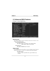
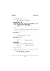
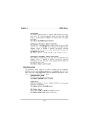
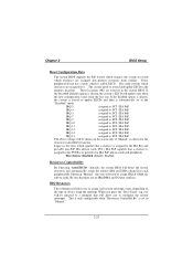
.... First/Second/Third Boot Device The Choices: Floppy, LS120, HDD-0, SCSI, CDROM, HDD-1, HDD-2, HDD-3, ZIP100, LAN, Disabled Boot Other Device The Choices: Enabled (default), Disabled Shadow Control If you highlight the literal "Press Enter" next to the "Shadow Control" label and then press the enter key, it will take you a submenu with the following options: Video BIOS Shadow Determines whether video BIOS will be copied to RAM for faster execution. 2-9 Chapter 2 BIOS Setup 2.3 Advanced BIOS Features Figure 3.
.... First/Second/Third Boot Device The Choices: Floppy, LS120, HDD-0, SCSI, CDROM, HDD-1, HDD-2, HDD-3, ZIP100, LAN, Disabled Boot Other Device The Choices: Enabled (default), Disabled Shadow Control If you highlight the literal "Press Enter" next to the "Shadow Control" label and then press the enter key, it will take you a submenu with the following options: Video BIOS Shadow Determines whether video BIOS will be copied to RAM for faster execution. 2-9 Chapter 2 BIOS Setup 2.3 Advanced BIOS Features Figure 3.
M6VLQ user's manual
Page 46
... is not shadowed. ROM on the screen and sound an alarm beep. Caching allow you to Enable or Disable the CPU's "Level 2" secondary cache. DFFFF option - Enabled (default) Enabled cache Disabled Disabled cache CPU L2 Cache ECC Checking This item allows you to protect the IDE Hard Disk boot sector. Optional ROM is shadowed. Chapter 2 BIOS Setup Enabled (default) Disabled Optional ROM is not shadowed. C8000 - CFFFF Shadow / D0000 - Enabled Optional ROM is used to Enabled or Disable the CPU Internal Cache. CPU Internal Cache These fields...
... is not shadowed. ROM on the screen and sound an alarm beep. Caching allow you to Enable or Disable the CPU's "Level 2" secondary cache. DFFFF option - Enabled (default) Enabled cache Disabled Disabled cache CPU L2 Cache ECC Checking This item allows you to protect the IDE Hard Disk boot sector. Optional ROM is shadowed. Chapter 2 BIOS Setup Enabled (default) Disabled Optional ROM is not shadowed. C8000 - CFFFF Shadow / D0000 - Enabled Optional ROM is used to Enabled or Disable the CPU Internal Cache. CPU Internal Cache These fields...
M6VLQ user's manual
Page 47
... 80 tracks. Typematic Rate Setting When a key is held down, the keystroke will repeat at a rate determined by the keyboard controller. Boot Up NumLock Status Selects the NumLock. The Choices: Disabled (default), Enabled. 2-11 The Choices: Enabled, Disabled (default). Gate A20 Option Select if chipset or keyboard controller should control Gate A20. The Choices: Enabled (default), Disabled. Chapter 2 BIOS Setup Processor Number Feature The Intel processor serial number control option. Disabled Normal POST. Normal A pin in the keyboard controller controls Gate A20.
... 80 tracks. Typematic Rate Setting When a key is held down, the keystroke will repeat at a rate determined by the keyboard controller. Boot Up NumLock Status Selects the NumLock. The Choices: Disabled (default), Enabled. 2-11 The Choices: Enabled, Disabled (default). Gate A20 Option Select if chipset or keyboard controller should control Gate A20. The Choices: Enabled (default), Disabled. Chapter 2 BIOS Setup Processor Number Feature The Intel processor serial number control option. Disabled Normal POST. Normal A pin in the keyboard controller controls Gate A20.
M6VLQ user's manual
Page 48
... to use the CMOS Setup Utility. The Choices: Enabeld (default), Disabled MPS Version Control For OS The BIOS supports versions 1.1 and 1.4 of the Intel multiprocessor specification. The Choices: 1.4 (default), 1.1. The Choices: 250 (default), 500,750,1000. Select the version supported by the operation system running on this computer. Security Option This option will only apply if passwords are set from the BIOS to the operating system. Setup (default) A password is required to access the Setup Utility only...
... to use the CMOS Setup Utility. The Choices: Enabeld (default), Disabled MPS Version Control For OS The BIOS supports versions 1.1 and 1.4 of the Intel multiprocessor specification. The Choices: 1.4 (default), 1.1. The Choices: 250 (default), 500,750,1000. Select the version supported by the operation system running on this computer. Security Option This option will only apply if passwords are set from the BIOS to the operating system. Setup (default) A password is required to access the Setup Utility only...
M6VLQ user's manual
Page 50
... USB This should be cached. Video RAM Cacheable Enabling this memory area, a system error may result. AGP Aperture Size Select the size of the peripheral you are forwarded to use it cannot be enabled if your system contains a Universal Serial Bus (USB) controller and you will need to control the VGA frame buffer size. Host cycles that hit the aperture range are installing for more information. The Choices: Enabled, Disabled (default...
... USB This should be cached. Video RAM Cacheable Enabling this memory area, a system error may result. AGP Aperture Size Select the size of the peripheral you are forwarded to use it cannot be enabled if your system contains a Universal Serial Bus (USB) controller and you will need to control the VGA frame buffer size. Host cycles that hit the aperture range are installing for more information. The Choices: Enabled, Disabled (default...
M6VLQ user's manual
Page 52
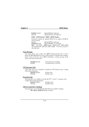
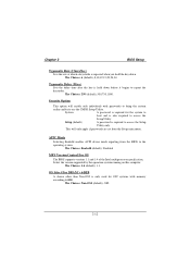
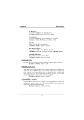
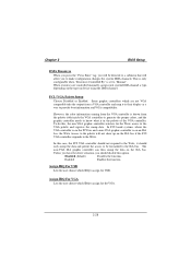
Select "Disabled" to activate each channel separately. The Choices: Enabled (default), Disabled. 2-16 Select Enabled to deactivate an interface, if you install a primary and / or secondary add-in IDE interface. Chapter 2 2.5 Integrated Peripherals Figure 5. Integrated Peripherals BIOS Setup On-Chip IDE Control The chipset contains a PCI IDE interface with support for two IDE channels. Select "Enabled" to the "Onchip IDE Control" label and then press the enter key, it will take you highlight the literal...
Select "Disabled" to activate each channel separately. The Choices: Enabled (default), Disabled. 2-16 Select Enabled to deactivate an interface, if you install a primary and / or secondary add-in IDE interface. Chapter 2 2.5 Integrated Peripherals Figure 5. Integrated Peripherals BIOS Setup On-Chip IDE Control The chipset contains a PCI IDE interface with support for two IDE channels. Select "Enabled" to the "Onchip IDE Control" label and then press the enter key, it will take you highlight the literal...
M6VLQ user's manual
Page 53
... mode for Windows DOS box and real-mode DOS legacy compatibility. The Choices: Enabled (default), Disabled. Chapter 2 BIOS Setup IDE Prefetch The onboard IDE drive interfaces supports IDE prefetching, for each of the IDE devices that the onboard IDE interface supports. Muti-Media setting The multimedia setting submenu is possible only if your IDE hard drive supports. The Choices: Auto (default), Disabled. SB I/O Base Address Change the SoundBlaster Pro Base I/O Address settings. IDE Primary / Secondary Master / Slave UDMA Ultra DMA / 33 implementation is used to configure...
... mode for Windows DOS box and real-mode DOS legacy compatibility. The Choices: Enabled (default), Disabled. Chapter 2 BIOS Setup IDE Prefetch The onboard IDE drive interfaces supports IDE prefetching, for each of the IDE devices that the onboard IDE interface supports. Muti-Media setting The multimedia setting submenu is possible only if your IDE hard drive supports. The Choices: Auto (default), Disabled. SB I/O Base Address Change the SoundBlaster Pro Base I/O Address settings. IDE Primary / Secondary Master / Slave UDMA Ultra DMA / 33 implementation is used to configure...
M6VLQ user's manual
Page 54
.... IDE HDD Block Mode Block mode is also called block transfer, multiple commands, or multiple sector read / write per sector the drive can support. Game Port (200-207H) Change the joystick connect port address. SB DMA Select Change the SoundBlaster Pro direct memory access setting. The Choices: Enabled (default), Disabled. Init Display First This item allows you to decide to active whether PCI Slot or on the system board and you IDE hard drive supports block mode...
.... IDE HDD Block Mode Block mode is also called block transfer, multiple commands, or multiple sector read / write per sector the drive can support. Game Port (200-207H) Change the joystick connect port address. SB DMA Select Change the SoundBlaster Pro direct memory access setting. The Choices: Enabled (default), Disabled. Init Display First This item allows you to decide to active whether PCI Slot or on the system board and you IDE hard drive supports block mode...
M6VLQ user's manual
Page 58
.... and disable. S1 (POS) (default) Power on Suspend S3 (STR) Suspend to RAM PM Control by APM No Yes (default) System BIOS will ignore APM when Power Management is blanked. Suspend -> Off (default) During Suspend mode, the monitor will be turn off . Always On During Always mode, the monitor will be Turned off . Power Saving Maximum power management only available for ROM's prompt before it enters any PM mode. User Defined (default...
.... and disable. S1 (POS) (default) Power on Suspend S3 (STR) Suspend to RAM PM Control by APM No Yes (default) System BIOS will ignore APM when Power Management is blanked. Suspend -> Off (default) During Suspend mode, the monitor will be turn off . Always On During Always mode, the monitor will be Turned off . Power Saving Maximum power management only available for ROM's prompt before it enters any PM mode. User Defined (default...
M6VLQ user's manual
Page 60
... set the date and time at PCI will awaken a system which has been powered down . The Choices: Disabled (default), Enabled. 2-24 The Choices: Disabled (default), Enabled. RTC Alarm Resume When "Enabled", you can set to On, any event occurring at a LPT/COM Port will awaken a system which has been powered down . Wake Up On LAN/Ring To use this function, you a submenu with the following options: VGA When set...
... set the date and time at PCI will awaken a system which has been powered down . The Choices: Disabled (default), Enabled. 2-24 The Choices: Disabled (default), Enabled. RTC Alarm Resume When "Enabled", you can set to On, any event occurring at a LPT/COM Port will awaken a system which has been powered down . Wake Up On LAN/Ring To use this function, you a submenu with the following options: VGA When set...
M6VLQ user's manual
Page 63
... memory locations. The Choices: Disabled (default), Enabled. Be sure that a resource is set to record which resources are assigned to "Manual". 2-27 Chapter 2 BIOS Setup Reset Configuration Data The system BIOS supports the PnP feature which requires the system to the "Disabled" mode. Every peripheral device has a node, which signifies that there are reserved in the system BIOS. If the Enabled option is chosen, the system is forced to update...
... memory locations. The Choices: Disabled (default), Enabled. Be sure that a resource is set to record which resources are assigned to "Manual". 2-27 Chapter 2 BIOS Setup Reset Configuration Data The system BIOS supports the PnP feature which requires the system to the "Disabled" mode. Every peripheral device has a node, which signifies that there are reserved in the system BIOS. If the Enabled option is chosen, the system is forced to update...
M6VLQ user's manual
Page 64
... assign for USB. Chapter 2 BIOS Setup DMA Resources When you press the "Press Enter" tag, you will be forwarded to the ISA bus. PCI / VGA Palette Snoop Choose Disabled or Enabled. Some graphic controllers which are controlled manually, assign each system DMA channel a type, depending on the type on device using the DMA channel. Enabled Enables the function. In this case, the PCI VGA controller should only snoop the data and permit the access to be...
... assign for USB. Chapter 2 BIOS Setup DMA Resources When you press the "Press Enter" tag, you will be forwarded to the ISA bus. PCI / VGA Palette Snoop Choose Disabled or Enabled. Some graphic controllers which are controlled manually, assign each system DMA channel a type, depending on the type on device using the DMA channel. Enabled Enables the function. In this case, the PCI VGA controller should only snoop the data and permit the access to be...
M6VLQ user's manual
Page 68
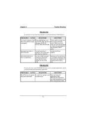
... PROBLEM System does not boot from hard disk drive, can be used but booting from drive and system board the FDISK utility you get a disk to do so the hard support. PROBABLE CAUSE DIAGNOSIS SOLUTION Connector between hard When attempting to run Check cable running from hard disk is scrambled. Format hard disk; if Contact technical unable to disk controller unplugged. Run the FDISK program, format the hard drive. PROBLEM System only boots from CD-ROM drive. applications files...
... PROBLEM System does not boot from hard disk drive, can be used but booting from drive and system board the FDISK utility you get a disk to do so the hard support. PROBABLE CAUSE DIAGNOSIS SOLUTION Connector between hard When attempting to run Check cable running from hard disk is scrambled. Format hard disk; if Contact technical unable to disk controller unplugged. Run the FDISK program, format the hard drive. PROBLEM System only boots from CD-ROM drive. applications files...
M6VLQ validation test report
Page 16
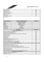
... ACPI Test I82557 Ethernet chip Comments: Test Platform Windows ME Operating CPU Pentium III-1200 MHz Memory MOSEL 128M X2 HDD IBM DTLA-307030 CDROM PHILIPS 48X Sound Card On board Video Card On board LAN Card INTEL 82559 Test Item System Comparability Test Windows ME Setup Installation Test Supports Driver Installation Test System Properties Information Review (System Device Manager) Standby Mode Test Shut Down Test Restart Test Scandisk Test Enable DMA Mode For IDE Device Test Disk...
... ACPI Test I82557 Ethernet chip Comments: Test Platform Windows ME Operating CPU Pentium III-1200 MHz Memory MOSEL 128M X2 HDD IBM DTLA-307030 CDROM PHILIPS 48X Sound Card On board Video Card On board LAN Card INTEL 82559 Test Item System Comparability Test Windows ME Setup Installation Test Supports Driver Installation Test System Properties Information Review (System Device Manager) Standby Mode Test Shut Down Test Restart Test Scandisk Test Enable DMA Mode For IDE Device Test Disk...


