
M6VLQ user's manual
Page 5
BIOS Setup 2-1 2.1 Main Menu 2-3 2.2 Standard CMOS Features 2-6 2.3 Advanced BIOS Features 2-9 2.4 Advanced Chipset Features 2-13 2.5 Integrated Peripherals 2-16 2.6 Power Management Setup 2-21 2.7 PnP/PCI Configurations 2-26 2.8 PC Health Status 2-29 2.9 Frequency Control 2-30 3. Trouble Shooting 3-1 iii Contents 1.7.6.3 Front Audio Header: JAUDIO1 1-31 1.7.6.4 Telephony Audio Header: JTAD1 1-31 2.
BIOS Setup 2-1 2.1 Main Menu 2-3 2.2 Standard CMOS Features 2-6 2.3 Advanced BIOS Features 2-9 2.4 Advanced Chipset Features 2-13 2.5 Integrated Peripherals 2-16 2.6 Power Management Setup 2-21 2.7 PnP/PCI Configurations 2-26 2.8 PC Health Status 2-29 2.9 Frequency Control 2-30 3. Trouble Shooting 3-1 iii Contents 1.7.6.3 Front Audio Header: JAUDIO1 1-31 1.7.6.4 Telephony Audio Header: JTAD1 1-31 2.
M6VLQ user's manual
Page 12
Supports PnP functions. Operating Systems − Offers the highest performance for MS-DOS, Windows NT, Windows 2000, Windows 95/ 98, Windows ME, Windows XP, Novell, LINUX (Red hat 7.0), SCO UNIT. 1.1.3 Attachments − HDD Cable. − FDD Cable. − USB2 Cable (Optional). − Rear I/O Panel for Micro ATX Case (Optional). − CD for sound, VGA, IDE drivers utilities. 1-7 Chapter 1 Motherboard Description 1.1.2 Software BIOS − − Phoenix legal & user-friendly BIOS.
Supports PnP functions. Operating Systems − Offers the highest performance for MS-DOS, Windows NT, Windows 2000, Windows 95/ 98, Windows ME, Windows XP, Novell, LINUX (Red hat 7.0), SCO UNIT. 1.1.3 Attachments − HDD Cable. − FDD Cable. − USB2 Cable (Optional). − Rear I/O Panel for Micro ATX Case (Optional). − CD for sound, VGA, IDE drivers utilities. 1-7 Chapter 1 Motherboard Description 1.1.2 Software BIOS − − Phoenix legal & user-friendly BIOS.
M6VLQ user's manual
Page 13
CONN. CNTL A D D R / D ATA SER. CONN. Chapter 1 Motherboard Description 1.2 Motherboard Installation 1.2.1 System Block Diagram SOCKET 370 CPU CLOCK W93194BR-39B CONTROL HOST BUS ADD DATA HOST BUS M6VLQ VT8601T PLE-T CNTL ADDR MEMORY D ATA AMR SLOT AC' 97 CODEC FLASH BIOS PCI BUS USB USB VT82C686B USB USB CNTL A D D R / D ATA ISA BUS IAS CONN KEYBOARD MOUSE FLOPPY LPT. CONN. LAN PCI CONN PCI CONN PCI CONN IDE IDE 1-8
CONN. CNTL A D D R / D ATA SER. CONN. Chapter 1 Motherboard Description 1.2 Motherboard Installation 1.2.1 System Block Diagram SOCKET 370 CPU CLOCK W93194BR-39B CONTROL HOST BUS ADD DATA HOST BUS M6VLQ VT8601T PLE-T CNTL ADDR MEMORY D ATA AMR SLOT AC' 97 CODEC FLASH BIOS PCI BUS USB USB VT82C686B USB USB CNTL A D D R / D ATA ISA BUS IAS CONN KEYBOARD MOUSE FLOPPY LPT. CONN. LAN PCI CONN PCI CONN PCI CONN IDE IDE 1-8
M6VLQ user's manual
Page 14
Chapter 1 Motherboard Description 1.2.2 Layout of Motherboard Model No.M6VLQ JKBMS1 JKBV1 JC FA N1 JUSBV1 JUSBLAN1 JCOM1 JPRNT1 FDD1 CPU1 DIMM1 DIMM2 FLOPPY DISK CONN. SECONDARY IDE CONN. IDE1 IDE2 JSFAN1 BIOS ROM1 21 JPANEL1 1-9 JVGA1 JSPKR1 SP-OUT JGAME1 GAME Port JLIN1 LINE-IN JMIC1 MIC-IN JAUDIO1 JWOL1 JATXPWR1 VT 8601T LAN 8100 AMR1 JWOM1 BAT1 JCMOS1 PCI1 JCDIN2 JCDIN1 JTAD1 JUSBV2 JUSB2 ISA1 PCI2 PCI3 VT 82C686B PRIMARY IDE CONN.
Chapter 1 Motherboard Description 1.2.2 Layout of Motherboard Model No.M6VLQ JKBMS1 JKBV1 JC FA N1 JUSBV1 JUSBLAN1 JCOM1 JPRNT1 FDD1 CPU1 DIMM1 DIMM2 FLOPPY DISK CONN. SECONDARY IDE CONN. IDE1 IDE2 JSFAN1 BIOS ROM1 21 JPANEL1 1-9 JVGA1 JSPKR1 SP-OUT JGAME1 GAME Port JLIN1 LINE-IN JMIC1 MIC-IN JAUDIO1 JWOL1 JATXPWR1 VT 8601T LAN 8100 AMR1 JWOM1 BAT1 JCMOS1 PCI1 JCDIN2 JCDIN1 JTAD1 JUSBV2 JUSB2 ISA1 PCI2 PCI3 VT 82C686B PRIMARY IDE CONN.
M6VLQ user's manual
Page 15
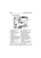
... USB (*JUSBV2) (*JUSBV1) J. Wake-On-Modem Header O. Clear CMOS Header (JCMOS1) G. Primary IDE Connector (IDE1) (*JWOM1) P. Back Panel I H G F E DC B A J W V U K T LAN S 8100 VT 8601T VT 82C686B BIOS L R DIMM1 Q DIMM2 M N O P A. ISA Slot (ISA1) W. CD-ROM Audio Header (JCDIN1) T. Wake-On-LAN Header (JWOL1) N. PCI Slots (PCI1-3) Q. Chapter 1 Motherboard Description 1.2.3 Quick Reference I /O Connectors L.
... USB (*JUSBV2) (*JUSBV1) J. Wake-On-Modem Header O. Clear CMOS Header (JCMOS1) G. Primary IDE Connector (IDE1) (*JWOM1) P. Back Panel I H G F E DC B A J W V U K T LAN S 8100 VT 8601T VT 82C686B BIOS L R DIMM1 Q DIMM2 M N O P A. ISA Slot (ISA1) W. CD-ROM Audio Header (JCDIN1) T. Wake-On-LAN Header (JWOL1) N. PCI Slots (PCI1-3) Q. Chapter 1 Motherboard Description 1.2.3 Quick Reference I /O Connectors L.
M6VLQ user's manual
Page 17
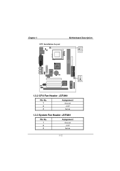
Chapter 1 CPU Installation Layout Motherboard Description 1 JCFAN1 DIMM1 DIMM2 VT 8601T LAN 8100 VT 82C686B 1 JSFAN1 BIOS 1.3.2 CPU Fan Header: JCFAN1 Pin No. 1 2 3 Assignment Ground +12V Sense 1.3.3 System Fan Header: JSFAN1 Pin No. 1 2 3 Assignment Ground +12V Sense 1-12
Chapter 1 CPU Installation Layout Motherboard Description 1 JCFAN1 DIMM1 DIMM2 VT 8601T LAN 8100 VT 82C686B 1 JSFAN1 BIOS 1.3.2 CPU Fan Header: JCFAN1 Pin No. 1 2 3 Assignment Ground +12V Sense 1.3.3 System Fan Header: JSFAN1 Pin No. 1 2 3 Assignment Ground +12V Sense 1-12
M6VLQ user's manual
Page 20
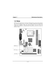
Expansion slots are a means of the basic system. DIMM1 DIMM2 BIOS AMR Slot PCI Slots ISA Slot VT 8601T LAN 8100 VT 82C686B 1-15 Chapter 1 Motherboard Description 1.5 Slots The slots in this motherboard are not part of adding or enhancing the motherboard's features and capabilities. With these efficient facilities, you can increase the motherboard's capabilities by adding hardware that performs tasks that are designed to hold expansion cards and connect them to the system bus.
Expansion slots are a means of the basic system. DIMM1 DIMM2 BIOS AMR Slot PCI Slots ISA Slot VT 8601T LAN 8100 VT 82C686B 1-15 Chapter 1 Motherboard Description 1.5 Slots The slots in this motherboard are not part of adding or enhancing the motherboard's features and capabilities. With these efficient facilities, you can increase the motherboard's capabilities by adding hardware that performs tasks that are designed to hold expansion cards and connect them to the system bus.
M6VLQ user's manual
Page 22
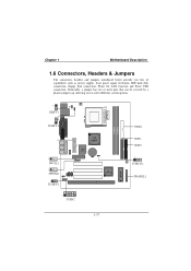
Noticeably, a jumper has two or more pins that can be covered by a plastic jumper cap, allowing you lots of capabilities such as power supply, front panel signal revelation, IDE hard disk connection, floppy disk connection, Wake On LAN function and Front USB connection. Chapter 1 Motherboard Description 1.6 Connectors, Headers & Jumpers The connectors, headers and jumpers introduced below provide you to select different system options. 1 JKBV1 1 JUSBV1 1 JWOL1 1 JWOM1 1 JUSBV2 VT 8601T LAN 8100 VT 82C686B 1 JUSB2 DIMM1 DIMM2 BIOS FDD1 IDE1 IDE2 1 JCMOS1 JPANEL1 1-17
Noticeably, a jumper has two or more pins that can be covered by a plastic jumper cap, allowing you lots of capabilities such as power supply, front panel signal revelation, IDE hard disk connection, floppy disk connection, Wake On LAN function and Front USB connection. Chapter 1 Motherboard Description 1.6 Connectors, Headers & Jumpers The connectors, headers and jumpers introduced below provide you to select different system options. 1 JKBV1 1 JUSBV1 1 JWOL1 1 JWOM1 1 JUSBV2 VT 8601T LAN 8100 VT 82C686B 1 JUSB2 DIMM1 DIMM2 BIOS FDD1 IDE1 IDE2 1 JCMOS1 JPANEL1 1-17
M6VLQ user's manual
Page 24
... need to the system board. The LED will cause the motherboard to a momentary SPST switch. APM (Advanced Power Management) must be enabled in the system BIOS and the APM driver must pass before the power supply will power down the monitor and hard drives until the system is invoked by powering...
... need to the system board. The LED will cause the motherboard to a momentary SPST switch. APM (Advanced Power Management) must be enabled in the system BIOS and the APM driver must pass before the power supply will power down the monitor and hard drives until the system is invoked by powering...
M6VLQ user's manual
Page 25
... has a 32-bit Enhanced PCI IDE Controller that the system will boot up to four hard disk drives, a CD-ROM, a 120MB Floppy (reserved for future BIOS) and other devices to slave mode. 1-20 The second drive on the board. It has two HDD connectors IDE1 (primary) and IDE2 (secondary). This power...
... has a 32-bit Enhanced PCI IDE Controller that the system will boot up to four hard disk drives, a CD-ROM, a 120MB Floppy (reserved for future BIOS) and other devices to slave mode. 1-20 The second drive on the board. It has two HDD connectors IDE1 (primary) and IDE2 (secondary). This power...
M6VLQ user's manual
Page 35
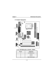
Chapter 1 1.7.6 Audio Subsystem Motherboard Description DIMM1 DIMM2 BIOS 1 JAUDIO1 1 JTAD1 VT 8602 LAN 8100 1 JCDIN2 1 JCDIN1 VT 82C686B 1.7.6.1 CD-ROM Audio-In Header: JCDIN1 Pin No. 1 2 3 4 Assignment Left Channel Input Ground Ground Right Channel Input 1-30
Chapter 1 1.7.6 Audio Subsystem Motherboard Description DIMM1 DIMM2 BIOS 1 JAUDIO1 1 JTAD1 VT 8602 LAN 8100 1 JCDIN2 1 JCDIN1 VT 82C686B 1.7.6.1 CD-ROM Audio-In Header: JCDIN1 Pin No. 1 2 3 4 Assignment Left Channel Input Ground Ground Right Channel Input 1-30
M6VLQ user's manual
Page 37
...such as disk drives and serial and parallel ports. Power to guide you through the process of this manual is supported. Chapter 2 BIOS Setup 2. This special information is then stored in your system using Setup. The rest of configuring your computer system's ROM (Read ...features are supported. Sleep and Suspend power management modes are implemented via the System Management Interrupt (SMI). EPA Green PC Support This AWARD BIOS supports Version 1.03 of the Advanced Power Management (APM) specification. The Setup program allows users to modify the basic system configuration. ...
...such as disk drives and serial and parallel ports. Power to guide you through the process of this manual is supported. Chapter 2 BIOS Setup 2. This special information is then stored in your system using Setup. The rest of configuring your computer system's ROM (Read ...features are supported. Sleep and Suspend power management modes are implemented via the System Management Interrupt (SMI). EPA Green PC Support This AWARD BIOS supports Version 1.03 of the Advanced Power Management (APM) specification. The Setup program allows users to modify the basic system configuration. ...
M6VLQ user's manual
Page 38
... the left (menu bar) Move to the item on Setup navigation keys Load previous values from CMOS Load the fail-safe defaults from BIOS default table Load the optimized defaults Save all the CMOS changes and exit 2-2 Exit Current page and return to Main Menu General help ... Page Setup Menu - Keystroke Up arrow Down arrow Left arrow Right arrow Move Enter PgUp key PgDn key + Key - Chapter 2 BIOS Setup PCI Bus Support This AWARD BIOS also supports Version 2.1 of the Intel PCI (Peripheral Component Interconnect) local bus specification. DRAM Support SDRAM (Synchronous DRAM) are supported.
... the left (menu bar) Move to the item on Setup navigation keys Load previous values from CMOS Load the fail-safe defaults from BIOS default table Load the optimized defaults Save all the CMOS changes and exit 2-2 Exit Current page and return to Main Menu General help ... Page Setup Menu - Keystroke Up arrow Down arrow Left arrow Right arrow Move Enter PgUp key PgDn key + Key - Chapter 2 BIOS Setup PCI Bus Support This AWARD BIOS also supports Version 2.1 of the Intel PCI (Peripheral Component Interconnect) local bus specification. DRAM Support SDRAM (Synchronous DRAM) are supported.
M6VLQ user's manual
Page 39
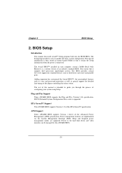
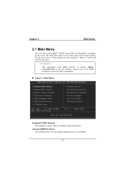
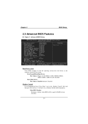
... among the items and press to configure enhanced features of the BIOS. 2-3 WARNING !! Advanced BIOS Features This submenu allows you to select from several setup functions. Figure 1. Chapter 2 BIOS Setup 2.1 Main Menu Once you enter Award BIOS™ CMOS Setup Utility, the Main Menu will appear on ...board, for reference, please refer to the BIOS installed on the screen. The Main Menu allows you to ...
... among the items and press to configure enhanced features of the BIOS. 2-3 WARNING !! Advanced BIOS Features This submenu allows you to select from several setup functions. Figure 1. Chapter 2 BIOS Setup 2.1 Main Menu Once you enter Award BIOS™ CMOS Setup Utility, the Main Menu will appear on ...board, for reference, please refer to the BIOS installed on the screen. The Main Menu allows you to ...
M6VLQ user's manual
Page 40
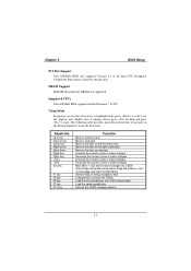
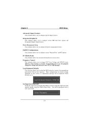
Chapter 2 BIOS Setup Advanced Chipset Features This submenu allows you to configure the power management features. Power Management Setup This submenu allows you to configure special chipset ... change CPU Vcore Voltage and CPU/PCI clock. (However, this system. These configurations are set. PnP/PCI Configurations This submenu allows you to reload the BIOS when the system is strongly recommended not to configure certain IDE hard drive options and Programmed Input/ Output features. Frequency Control This submenu allows you...
Chapter 2 BIOS Setup Advanced Chipset Features This submenu allows you to configure the power management features. Power Management Setup This submenu allows you to configure special chipset ... change CPU Vcore Voltage and CPU/PCI clock. (However, this system. These configurations are set. PnP/PCI Configurations This submenu allows you to reload the BIOS when the system is strongly recommended not to configure certain IDE hard drive options and Programmed Input/ Output features. Frequency Control This submenu allows you...
M6VLQ user's manual
Page 41
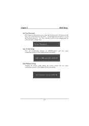
Chapter 2 BIOS Setup Set User Password If the Supervisor Password is set , then the User Password will function in the same way as the Supervisor Password. If ...
Chapter 2 BIOS Setup Set User Password If the Supervisor Password is set , then the User Password will function in the same way as the Supervisor Password. If ...
M6VLQ user's manual
Page 42
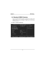
Chapter 2 BIOS Setup 2.2 Standard CMOS Features The items in each item. Figure 2. Each category includes no, one or more than one setup items. Use the arrow keys to highlight the item and then use the or keys to select the value you want in Standard CMOS Setup Menu are divided into 10 categories. Standard CMOS Setup 2-6
Chapter 2 BIOS Setup 2.2 Standard CMOS Features The items in each item. Figure 2. Each category includes no, one or more than one setup items. Use the arrow keys to highlight the item and then use the or keys to select the value you want in Standard CMOS Setup Menu are divided into 10 categories. Standard CMOS Setup 2-6
M6VLQ user's manual
Page 43
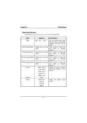
.... CGA 80 MONO 2-7 Note that you set the date. Drive A 360K, 5.25 in 1.2M, 5.25 in 720K, 3.5 in Select the type of detailed options. Chapter 2 BIOS Setup Main Menu Selections This table shows the selections that the 'Day' automatically changes when you can make on the Main Menu. sub menu of...
.... CGA 80 MONO 2-7 Note that you set the date. Drive A 360K, 5.25 in 1.2M, 5.25 in 720K, 3.5 in Select the type of detailed options. Chapter 2 BIOS Setup Main Menu Selections This table shows the selections that the 'Day' automatically changes when you can make on the Main Menu. sub menu of...
M6VLQ user's manual
Page 44
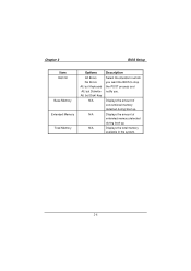
Displays the total memory available in which you want the BIOS to stop the POST process and notify you. Displays the amount of conventional memory detected during boot up . Chapter 2 BIOS Setup Item Halt On Base Memory Extended Memory Total Memory Options All Errors No Errors All, but Keyboard All, but Diskette All, but Disk/ Key N/A N/A N/A Description Select the situation in the system. 2-8 Displays the amount of extended memory detected during boot up .
Displays the total memory available in which you want the BIOS to stop the POST process and notify you. Displays the amount of conventional memory detected during boot up . Chapter 2 BIOS Setup Item Halt On Base Memory Extended Memory Total Memory Options All Errors No Errors All, but Keyboard All, but Diskette All, but Disk/ Key N/A N/A N/A Description Select the situation in the system. 2-8 Displays the amount of extended memory detected during boot up .
M6VLQ user's manual
Page 45
... Boot Device select These BIOS attempts to load the operating system from the devices in the sequence selected in these items. First/Second/Third Boot Device The Choices: Floppy, LS120, ... literal "Press Enter" next to the "Shadow Control" label and then press the enter key, it will take you a submenu with the following options: Video BIOS Shadow Determines whether video BIOS will be copied to RAM for faster execution. 2-9 Chapter...
... Boot Device select These BIOS attempts to load the operating system from the devices in the sequence selected in these items. First/Second/Third Boot Device The Choices: Floppy, LS120, ... literal "Press Enter" next to the "Shadow Control" label and then press the enter key, it will take you a submenu with the following options: Video BIOS Shadow Determines whether video BIOS will be copied to RAM for faster execution. 2-9 Chapter...

