

K8M800 MICRO AM2 user's manual
Page 2
Table of Contents Chapter 1: Introduction 1 1.1 Before You Start 1 1.2 Package Checklist 1 1.3 Motherboard Features 2 1.4 Rear Panel Connectors 3 1.5 Motherboard Layout 4 Chapter 2: Hardware Installation 5 2.1 Installing Central Processing Unit (CPU 5 2.2 FAN Headers 7 2.3 Installing System Memory 8 2.4 Connectors and Slots 10 Chapter 3: Headers & Jumpers Setup 12 3.1 How to ...
Table of Contents Chapter 1: Introduction 1 1.1 Before You Start 1 1.2 Package Checklist 1 1.3 Motherboard Features 2 1.4 Rear Panel Connectors 3 1.5 Motherboard Layout 4 Chapter 2: Hardware Installation 5 2.1 Installing Central Processing Unit (CPU 5 2.2 FAN Headers 7 2.3 Installing System Memory 8 2.4 Connectors and Slots 10 Chapter 3: Headers & Jumpers Setup 12 3.1 How to ...

K8M800 MICRO AM2 user's manual
Page 3
... Setup Driver CD X 1 Rear I/O Panel for choosing our product. K8M800 Micro AM2 CHAPTER 1: INTRODUCTION 1.1 BEFORE YOU START Thank you take the motherboard out from anti-static bag, ground yourself properly by touching any safely grounded appliance, or use grounded wrist strap to bend or flex the board.... „ Do not leave any unfastened small parts inside the case after installation. Before you start installing the motherboard, please make sure you follow the instructions below: „ Prepare a dry and stable working environment with sufficient lighting. „ Always...
... Setup Driver CD X 1 Rear I/O Panel for choosing our product. K8M800 Micro AM2 CHAPTER 1: INTRODUCTION 1.1 BEFORE YOU START Thank you take the motherboard out from anti-static bag, ground yourself properly by touching any safely grounded appliance, or use grounded wrist strap to bend or flex the board.... „ Do not leave any unfastened small parts inside the case after installation. Before you start installing the motherboard, please make sure you follow the instructions below: „ Prepare a dry and stable working environment with sufficient lighting. „ Always...

K8M800 MICRO AM2 user's manual
Page 4
... function) x1 System Fan Power supply x1 Restore CMOS data to factory default x2 Each connector supports 2 front panel USB ports SATA Version 1.0 specification compliant. Motherboard Manual 1.3 MOTHERBOARD FEATURES SPEC Socket AM2 CPU AMD Sempron processors Supports Hyper Transport and Cool=n=Quiet FSB Chipset Support HyperTransport K8M800 VT8237R+ Supports up to 1.5 Gb/s.
... function) x1 System Fan Power supply x1 Restore CMOS data to factory default x2 Each connector supports 2 front panel USB ports SATA Version 1.0 specification compliant. Motherboard Manual 1.3 MOTHERBOARD FEATURES SPEC Socket AM2 CPU AMD Sempron processors Supports Hyper Transport and Cool=n=Quiet FSB Chipset Support HyperTransport K8M800 VT8237R+ Supports up to 1.5 Gb/s.

K8M800 MICRO AM2 user's manual
Page 6
Motherboard Manual 1.5 MOTHERBOARD LAYOUT JKBMS1 JATXPWR1 DIMMA1 DIMMB1 FDD1 Socket A M2 JPRNT1 JCOM1 JVGA1 IDE1 IDE2 JUSB1 JUSBLAN1 JATXPWR2 JCFAN1 JAUDIO1 K8M800 Super I/O LAN AGP1 BIOS PCI1 Codec PCI2 JAUDIO2 JCDIN1 JSPDIF_OUT1 JSFAN1 Note: ■ represents the 1st pin. 4 BAT1 VT8237R+ JCMOS1 JSATA2 JUSB2 JUSB3 JSATA1 JPANEL1
Motherboard Manual 1.5 MOTHERBOARD LAYOUT JKBMS1 JATXPWR1 DIMMA1 DIMMB1 FDD1 Socket A M2 JPRNT1 JCOM1 JVGA1 IDE1 IDE2 JUSB1 JUSBLAN1 JATXPWR2 JCFAN1 JAUDIO1 K8M800 Super I/O LAN AGP1 BIOS PCI1 Codec PCI2 JAUDIO2 JCDIN1 JSPDIF_OUT1 JSFAN1 Note: ■ represents the 1st pin. 4 BAT1 VT8237R+ JCMOS1 JSATA2 JUSB2 JUSB3 JSATA1 JPANEL1
K8M800 MICRO AM2 user's manual
Page 8
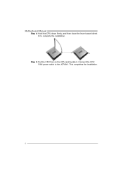
Motherboard Manual Step 4: Hold the CPU down firmly, and then close the lever toward direct B to the JCFAN1. This completes the installation. 6 Step 5: Put the CPU Fan on the CPU and buckle it. Connect the CPU FAN power cable to complete the installation.
Motherboard Manual Step 4: Hold the CPU down firmly, and then close the lever toward direct B to the JCFAN1. This completes the installation. 6 Step 5: Put the CPU Fan on the CPU and buckle it. Connect the CPU FAN power cable to complete the installation.

K8M800 MICRO AM2 user's manual
Page 10
Insert the DIMM vertically and firmly into the slot until the retaining chip snap back in place and the DIMM is properly seated. B. Unlock a DIMM slot by pressing the retaining clips outward. Memory Capacity DIMM Socket Location DIMMA1 DIMMB1 DDR Module 256MB/512MB/1GB *1 256MB/512MB/1GB *1 Total Memory Size Max memory 2GB. 8 DDR2 module DIMMA1 DIMMB1 1. Motherboard Manual 2.3 INSTALLING SYSTEM MEMORY A. Align a DIMM on the slot such that the notch on the DIMM matches the break on the Slot. 2.
Insert the DIMM vertically and firmly into the slot until the retaining chip snap back in place and the DIMM is properly seated. B. Unlock a DIMM slot by pressing the retaining clips outward. Memory Capacity DIMM Socket Location DIMMA1 DIMMB1 DDR Module 256MB/512MB/1GB *1 256MB/512MB/1GB *1 Total Memory Size Max memory 2GB. 8 DDR2 module DIMMA1 DIMMB1 1. Motherboard Manual 2.3 INSTALLING SYSTEM MEMORY A. Align a DIMM on the slot such that the notch on the DIMM matches the break on the Slot. 2.

K8M800 MICRO AM2 user's manual
Page 11
Dual Channel Status DIMMA1 DIMMB1 Disabled O X Disabled X O Enabled O O (O means memory installed, X means memory not installed.) The DRAM bus width of the same density in pair, shown in the following table. Dual Channel Memory installation To trigger the Dual Channel function of the motherboard, the memory module must meet the following requirements: Install memory module of the memory module must be the same (x8 or x16) 9 K8M800 Micro AM2 C.
Dual Channel Status DIMMA1 DIMMB1 Disabled O X Disabled X O Enabled O O (O means memory installed, X means memory not installed.) The DRAM bus width of the same density in pair, shown in the following table. Dual Channel Memory installation To trigger the Dual Channel function of the motherboard, the memory module must meet the following requirements: Install memory module of the memory module must be the same (x8 or x16) 9 K8M800 Micro AM2 C.
K8M800 MICRO AM2 user's manual
Page 12
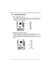
... IDE1. 40 39 2 1 IDE1 IDE2 10 The first hard drive should always be connected to four hard disk drives. Motherboard Manual 2.4 CONNECTORS AND SLOTS FDD1: Floppy Disk Connector The motherboard provides a standard floppy disk connector that provides PIO Mode 0~4, Bus Master, and Ultra DMA 33/66/100/133 functionality. ...This connector supports the provided floppy drive ribbon cables. 34 33 2 1 IDE1/IDE2: Hard Disk Connectors The motherboard has a 32-bit Enhanced PCI IDE Controller that supports 360K, 720K, 1.2M, 1.44M and 2.88M floppy disk types.
... IDE1. 40 39 2 1 IDE1 IDE2 10 The first hard drive should always be connected to four hard disk drives. Motherboard Manual 2.4 CONNECTORS AND SLOTS FDD1: Floppy Disk Connector The motherboard provides a standard floppy disk connector that provides PIO Mode 0~4, Bus Master, and Ultra DMA 33/66/100/133 functionality. ...This connector supports the provided floppy drive ribbon cables. 34 33 2 1 IDE1/IDE2: Hard Disk Connectors The motherboard has a 32-bit Enhanced PCI IDE Controller that supports 360K, 720K, 1.2M, 1.44M and 2.88M floppy disk types.

K8M800 MICRO AM2 user's manual
Page 13
... Slot Your monitor will take advantage of AGP technology for expansion cards. An AGP card will attach directly to that video card. AGP1 11 This motherboard supports video cards for PCI slots, but it is also equipped with an Accelerated Graphics Port (AGP). This PCI slot is equipped with 3D graphics...
... Slot Your monitor will take advantage of AGP technology for expansion cards. An AGP card will attach directly to that video card. AGP1 11 This motherboard supports video cards for PCI slots, but it is also equipped with an Accelerated Graphics Port (AGP). This PCI slot is equipped with 3D graphics...

K8M800 MICRO AM2 user's manual
Page 14
... (+) Hard drive LED 13 Power LED (+) 14 Power LED (-) Reset button 15 Power button 16 Ground Function Sleep button N/A Power LED Power-on button 12 Motherboard Manual CHAPTER 3: HEADERS & JUMPERS SETUP 3.1 HOW TO SETUP JUMPERS The illustration shows how to connect the PC case's front panel switch functions.
... (+) Hard drive LED 13 Power LED (+) 14 Power LED (-) Reset button 15 Power button 16 Ground Function Sleep button N/A Power LED Power-on button 12 Motherboard Manual CHAPTER 3: HEADERS & JUMPERS SETUP 3.1 HOW TO SETUP JUMPERS The illustration shows how to connect the PC case's front panel switch functions.
K8M800 MICRO AM2 user's manual
Page 16
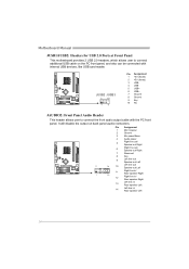
... NC JAUDIO2: Front Panel Audio Header This header allows user to connect additional USB cable on back panel audio connectors. Motherboard Manual JUSB1/JUSB2: Headers for USB 2.0 Ports at Front Panel This motherboard provides 2 USB 2.0 headers, which allows user to connect the front audio output cable with internal USB devices, like USB...
... NC JAUDIO2: Front Panel Audio Header This header allows user to connect additional USB cable on back panel audio connectors. Motherboard Manual JUSB1/JUSB2: Headers for USB 2.0 Ports at Front Panel This motherboard provides 2 USB 2.0 headers, which allows user to connect the front audio output cable with internal USB devices, like USB...
K8M800 MICRO AM2 user's manual
Page 17
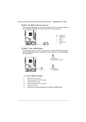
... Channel Input 2 Ground 3 Ground 4 Right Channel Input JCMOS1: Clear CMOS Header By placing the jumper on the AC. 6. Set the jumper to avoid damaging the motherboard. 1 3 Pin 1-2 Close: Normal Operation (Default). 1 3 1 Pin 2-3 Close: 3 Clear CMOS data. ※ Clear CMOS Procedures: 1.
... Channel Input 2 Ground 3 Ground 4 Right Channel Input JCMOS1: Clear CMOS Header By placing the jumper on the AC. 6. Set the jumper to avoid damaging the motherboard. 1 3 Pin 1-2 Close: Normal Operation (Default). 1 3 1 Pin 2-3 Close: 3 Clear CMOS data. ※ Clear CMOS Procedures: 1.
K8M800 MICRO AM2 user's manual
Page 18
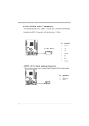
Motherboard Manual JSATA1~JSATA2: Serial ATA Connectors The motherboard has a PCI to connect the PCI bracket SPDIF output header. 13 Pin Assignment 1 +5V 2 SPDIF_OUT1 3 Ground 16 JSATA1 JSATA2 741 Pin Assignment 1 Ground 2 TX+ 3 TX4 Ground 5 RX6 RX+ 7 Ground JSPDIF_OUT1: Digital Audio out Connectors This connector allows user to SATA Controller with 2 channels SATA interface, it satisfies the SATA 1.0 spec and with transfer rate of 1.5Gb/s.
Motherboard Manual JSATA1~JSATA2: Serial ATA Connectors The motherboard has a PCI to connect the PCI bracket SPDIF output header. 13 Pin Assignment 1 +5V 2 SPDIF_OUT1 3 Ground 16 JSATA1 JSATA2 741 Pin Assignment 1 Ground 2 TX+ 3 TX4 Ground 5 RX6 RX+ 7 Ground JSPDIF_OUT1: Digital Audio out Connectors This connector allows user to SATA Controller with 2 channels SATA interface, it satisfies the SATA 1.0 spec and with transfer rate of 1.5Gb/s.

K8M800 MICRO AM2 user's manual
Page 20
Motherboard Manual RAID 1: Every read and write is actually carried out in parallel across 2 disk drives in the array. RAID 1 provides a hot-standby copy of data ...
Motherboard Manual RAID 1: Every read and write is actually carried out in parallel across 2 disk drives in the array. RAID 1 provides a hot-standby copy of data ...

K8M800 MICRO AM2 user's manual
Page 21
...: You will need Acrobat Reader to locate and execute the file SETUP.EXE under your optical drive. The setup guide will auto detect your motherboard and operating system. C. Note: If this window didn't show up after you insert the CD The setup guide will list the compatible driver... After you installed your operating system, please insert the Fully Setup Driver CD into your optical drive and install the driver for your motherboard and operating system. Software Installation To install the software, please click on the Driver icon. You will list the software available for your...
...: You will need Acrobat Reader to locate and execute the file SETUP.EXE under your optical drive. The setup guide will auto detect your motherboard and operating system. C. Note: If this window didn't show up after you insert the CD The setup guide will list the compatible driver... After you installed your operating system, please insert the Fully Setup Driver CD into your optical drive and install the driver for your motherboard and operating system. Software Installation To install the software, please click on the Driver icon. You will list the software available for your...

K8M800 MICRO AM2 user's manual
Page 22
... has been recovered and will boot-up to DOS prompt. 7. Confirm motherboard model and download the respectively BIOS from the Biostar website: www.biostar.com.tw 3. System will work properly. 20 Download the Flash Utility "AWDFLASH.exe" from Biostar website. 4. Make a bootable floppy disk. 2. Type "Awdflash xxxx.... system, it means the BIOS contents are corrupted. In this Case, please follow the procedure below to restore the BIOS: 1. Motherboard Manual 5.2 AWARD BIOS BEEP CODE Beep Sound Meaning One long beep followed by virus, the Boot-Block function will help to restore...
... has been recovered and will boot-up to DOS prompt. 7. Confirm motherboard model and download the respectively BIOS from the Biostar website: www.biostar.com.tw 3. System will work properly. 20 Download the Flash Utility "AWDFLASH.exe" from Biostar website. 4. Make a bootable floppy disk. 2. Type "Awdflash xxxx.... system, it means the BIOS contents are corrupted. In this Case, please follow the procedure below to restore the BIOS: 1. Motherboard Manual 5.2 AWARD BIOS BEEP CODE Beep Sound Meaning One long beep followed by virus, the Boot-Block function will help to restore...

K8M800 MICRO AM2 user's manual
Page 23
... with the CPU speed. CPU Overheated If the system shutdown automatically after power on the system again. 21 CPU fan speed is over heated, the motherboard will shutdown automatically to relief the CPU protection function. 1. Remove the power cord from power supply for seconds, that means the CPU protection function has...
... with the CPU speed. CPU Overheated If the system shutdown automatically after power on the system again. 21 CPU fan speed is over heated, the motherboard will shutdown automatically to relief the CPU protection function. 1. Remove the power cord from power supply for seconds, that means the CPU protection function has...
K8M800 MICRO AM2 user's manual
Page 24
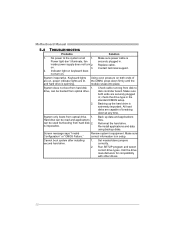
... down firmly until the module snaps into place. Reformat the hard drive. System inoperative. Review system's equipment. Run SETUP program and select correct drive types. Motherboard Manual 5.4 TROUBLESHOOTING Probable Solution 1. is extremely important. Call the drive manufacturers for compatibility with other drives. 22 Backing up data and applications files.
... down firmly until the module snaps into place. Reformat the hard drive. System inoperative. Review system's equipment. Run SETUP program and select correct drive types. Motherboard Manual 5.4 TROUBLESHOOTING Probable Solution 1. is extremely important. Call the drive manufacturers for compatibility with other drives. 22 Backing up data and applications files.

K8M800 MICRO AM2 user's manual
Page 26
..., the Tray Icon utility and [WarpSpeeder™] utility will be automatically and immediately launched after you see the following dialog will change according to install. 2. Motherboard Manual 6.3 INSTALLATION 1. If the "Launch the WarpSpeeder Tray Utility" checkbox is completed. Please click "Next" button and follow the default procedure to your...
..., the Tray Icon utility and [WarpSpeeder™] utility will be automatically and immediately launched after you see the following dialog will change according to install. 2. Motherboard Manual 6.3 INSTALLATION 1. If the "Launch the WarpSpeeder Tray Utility" checkbox is completed. Please click "Next" button and follow the default procedure to your...
K8M800 MICRO AM2 user's manual
Page 28
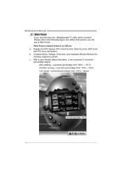
.... Please refer to the following figure; Contains About, Voltage, Overclock, and Hardware Monitor Buttons for invoking respective panels. Main Panel If you will be invoked. Motherboard Manual 2.
.... Please refer to the following figure; Contains About, Voltage, Overclock, and Hardware Monitor Buttons for invoking respective panels. Main Panel If you will be invoked. Motherboard Manual 2.

