
K8M800-M7A user's manual
Page 3
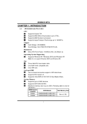
Chipset North Bridge: VIA K8M800. Slot Three 32bit PCI bus master slots. Supports PIO mode 0~4. Supports DDR-266/333/400. One AGP 4x/8x compatible slot. One CNR slot. System ... DDR Module Total Memory Size 128MB/256MB/512MB/1GB *1 128MB/256MB/512MB/1GB *1 Max is 2 GB. 1 Supports AMD Athlon 64 processor up to 3700+. K8M800-M7A CHAPTER 1: INTRODUCTION 1.1 MOTHERBOARD FEATURES CPU Supports Socket 754. Dimensions Micro ATX Form Factor: 18.999cm (W) x 24.384cm (L) Operating System Supporting Supports Windows NT, Windows 2000 and Windows...
Chipset North Bridge: VIA K8M800. Slot Three 32bit PCI bus master slots. Supports PIO mode 0~4. Supports DDR-266/333/400. One AGP 4x/8x compatible slot. One CNR slot. System ... DDR Module Total Memory Size 128MB/256MB/512MB/1GB *1 128MB/256MB/512MB/1GB *1 Max is 2 GB. 1 Supports AMD Athlon 64 processor up to 3700+. K8M800-M7A CHAPTER 1: INTRODUCTION 1.1 MOTHERBOARD FEATURES CPU Supports Socket 754. Dimensions Micro ATX Form Factor: 18.999cm (W) x 24.384cm (L) Operating System Supporting Supports Windows NT, Windows 2000 and Windows...
K8M800-M7A user's manual
Page 10
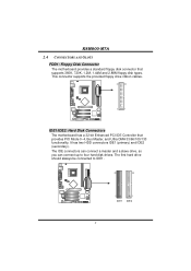
... connectors can connect a master and a slave drive, so you can connect up to IDE1. 40 39 2 IDE1 1 IDE2 8 K8M800-M7A 2.4 CONNECTORS AND SLOTS FDD1: Floppy Disk Connector The motherboard provides a standard floppy disk connector that provides PIO Mode 0~4, Bus Master, and Ultra DMA 33/66/100/133 functionality. It has ... to four hard disk drives. This connector supports the provided floppy drive ribbon cables. 34 33 2 1 IDE1/IDE2: Hard Disk Connectors The motherboard has a 32-bit Enhanced PCI IDE Controller that supports 360K, 720K, 1.2M, 1.44M and 2.88M floppy disk types.
... connectors can connect a master and a slave drive, so you can connect up to IDE1. 40 39 2 IDE1 1 IDE2 8 K8M800-M7A 2.4 CONNECTORS AND SLOTS FDD1: Floppy Disk Connector The motherboard provides a standard floppy disk connector that provides PIO Mode 0~4, Bus Master, and Ultra DMA 33/66/100/133 functionality. It has ... to four hard disk drives. This connector supports the provided floppy drive ribbon cables. 34 33 2 1 IDE1/IDE2: Hard Disk Connectors The motherboard has a 32-bit Enhanced PCI IDE Controller that supports 360K, 720K, 1.2M, 1.44M and 2.88M floppy disk types.
K8M800-M7A user's manual
Page 11
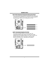
This motherboard supports video cards for PCI slots, but it is also equipped with an Accelerated Graphics Port (AGP). PCI1 PCI2 PCI3 AGP1: Accelerated Graphics Port Slot ... that video card. PCI stands for Peripheral Component Interconnect, and it is a bus standard for improved video efficiency and performance, especially with 3 standard PCI slots. K8M800-M7A PCI1~PCI3: Peripheral Component Interconnect Slots This motherboard is designated as 32 bits. This PCI slot is equipped with 3D graphics. 9
This motherboard supports video cards for PCI slots, but it is also equipped with an Accelerated Graphics Port (AGP). PCI1 PCI2 PCI3 AGP1: Accelerated Graphics Port Slot ... that video card. PCI stands for Peripheral Component Interconnect, and it is a bus standard for improved video efficiency and performance, especially with 3 standard PCI slots. K8M800-M7A PCI1~PCI3: Peripheral Component Interconnect Slots This motherboard is designated as 32 bits. This PCI slot is equipped with 3D graphics. 9
K8M800-M7A user's manual
Page 17
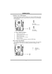
... the CMOS data, please carefully follow the procedures to the CMOS and show the message on next boot-up. K8M800-M7A JCMOS1: Clear CMOS Header By placing the jumper on pin2-3, it will record to avoid damaging the motherboard. 1 3 Pin 1-2 Close: Normal Operation (default). 1 1 3 3 Pin 2-3 Close: Clear CMOS data. ※ Clear CMOS Procedures...
... the CMOS data, please carefully follow the procedures to the CMOS and show the message on next boot-up. K8M800-M7A JCMOS1: Clear CMOS Header By placing the jumper on pin2-3, it will record to avoid damaging the motherboard. 1 3 Pin 1-2 Close: Normal Operation (default). 1 1 3 3 Pin 2-3 Close: Clear CMOS data. ※ Clear CMOS Procedures...
K8M800-M7A user's manual
Page 18
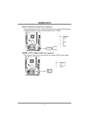
K8M800-M7A JSATA1~JSATA2: Serial ATA Connectors The motherboard has a PCI to SATA Controller with 2 channels SATA interface, it satisfies the SATA 1.0 spec and with transfer rate of 1.5GB/s. 741 Pin Assignment 1 Ground 2 TX+ 3 TX4 Ground 5 RX6 RX+ 7 Ground JSATA1 JSPDIF_OUT1: Digital Audio-out Connector This connector allows user to connect the PCI bracket SPDIF output header. 1 3 Pin Assignment 1 +5V 2 SPDIF_OUT 3 Ground 16
K8M800-M7A JSATA1~JSATA2: Serial ATA Connectors The motherboard has a PCI to SATA Controller with 2 channels SATA interface, it satisfies the SATA 1.0 spec and with transfer rate of 1.5GB/s. 741 Pin Assignment 1 Ground 2 TX+ 3 TX4 Ground 5 RX6 RX+ 7 Ground JSATA1 JSPDIF_OUT1: Digital Audio-out Connector This connector allows user to connect the PCI bracket SPDIF output header. 1 3 Pin Assignment 1 +5V 2 SPDIF_OUT 3 Ground 16
K8M800-M7A user's manual
Page 19
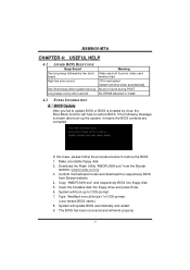
... update BIOS or BIOS is shown after boot-up to restore BIOS. Confirm motherboard model and download the respectively BIOS from the Biostar website: www.biostar.com.tw 3. Type "Awdflash xxxx.bf/sn/py/r" in DOS prompt. (xxxx means BIOS name.) 8. K8M800-M7A CHAPTER 4: USEFUL HELP 4.1 AWARD BIOS BEEP CODE Beep Sound One long beep... DRAM detected or install 4.2 EXTRA INFORMATION A. In this Case, please follow the procedure below to restore the BIOS: 1. Download the Flash Utility "AWDFLASH.exe" from Biostar website. 4.
... update BIOS or BIOS is shown after boot-up to restore BIOS. Confirm motherboard model and download the respectively BIOS from the Biostar website: www.biostar.com.tw 3. Type "Awdflash xxxx.bf/sn/py/r" in DOS prompt. (xxxx means BIOS name.) 8. K8M800-M7A CHAPTER 4: USEFUL HELP 4.1 AWARD BIOS BEEP CODE Beep Sound One long beep... DRAM detected or install 4.2 EXTRA INFORMATION A. In this Case, please follow the procedure below to restore the BIOS: 1. Download the Flash Utility "AWDFLASH.exe" from Biostar website. 4.
K8M800-M7A user's manual
Page 20
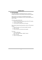
.... 18 Or you can: 1. Power on again. Wait for seconds. 2. Clear the CMOS data. (See "Close CMOS Header: JCMOS1" section) 2. K8M800-M7A B. Remove the power cord from power supply for seconds. 3. The CPU cooler surface is rotated normally. 3. CPU Overheated If the system shutdown automatically after ...system for seconds. 3. Plug in the power cord and boot up the system. CPU fan speed is over heated, the motherboard will shutdown automatically to relief the CPU protection function. 1. Wait for seconds, that means the CPU protection function has been activated.
.... 18 Or you can: 1. Power on again. Wait for seconds. 2. Clear the CMOS data. (See "Close CMOS Header: JCMOS1" section) 2. K8M800-M7A B. Remove the power cord from power supply for seconds. 3. The CPU cooler surface is rotated normally. 3. CPU Overheated If the system shutdown automatically after ...system for seconds. 3. Plug in the power cord and boot up the system. CPU fan speed is over heated, the motherboard will shutdown automatically to relief the CPU protection function. 1. Wait for seconds, that means the CPU protection function has been activated.
K8M800-M7A user's manual
Page 23
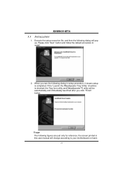
... see the following dialog in this user manual will pop up. Please click "Next" button and follow the default procedure to your motherboard on hand. 21 When you click "Finish" button. If the "Launch the WarpSpeeder Tray Utility" checkbox is completed. K8M800-M7A 5.3 INSTALLATION 1. Usage: The following dialog will change according to install. 2.
... see the following dialog in this user manual will pop up. Please click "Next" button and follow the default procedure to your motherboard on hand. 21 When you click "Finish" button. If the "Launch the WarpSpeeder Tray Utility" checkbox is completed. K8M800-M7A 5.3 INSTALLATION 1. Usage: The following dialog will change according to install. 2.

