
MANUAL
Page 3
... 3 Section 2 Motherboard Set Up 2.1 Motherboard Features 6 2.2 Layout & Components 10 2.3 Central Processing Unit (CPU 11 2.4 Fan Headers 13 2.5 Memory Modules Installation 13 2.6 Connectors, & Slots 14 2.7 How to setup Jumpers 15 2.8 Detail Settings 15 Section 3 Peripheral Connections 3.1 Overview 20 3.2 Connecting Peripheral Devices 21 Section 4 Software Utility 4.1 Installing Drives and Utilities 28 4.2 NVIDIA RAID 30 Section 5 Trouble Shooting 5.1 System Does Not Start 36 5.2 Keyboard and Mouse Problems 36 5.3 USB Device Problems 37 5.4 Software Problem 37 Section 5 Taking...
... 3 Section 2 Motherboard Set Up 2.1 Motherboard Features 6 2.2 Layout & Components 10 2.3 Central Processing Unit (CPU 11 2.4 Fan Headers 13 2.5 Memory Modules Installation 13 2.6 Connectors, & Slots 14 2.7 How to setup Jumpers 15 2.8 Detail Settings 15 Section 3 Peripheral Connections 3.1 Overview 20 3.2 Connecting Peripheral Devices 21 Section 4 Software Utility 4.1 Installing Drives and Utilities 28 4.2 NVIDIA RAID 30 Section 5 Trouble Shooting 5.1 System Does Not Start 36 5.2 Keyboard and Mouse Problems 36 5.3 USB Device Problems 37 5.4 Software Problem 37 Section 5 Taking...
MANUAL
Page 4
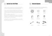
1.1 Begin Your Tour In The DIY World 1.2 Checking the Equipments Mini PC System Driver CD Software CD User's Manual Installation Guide Thermal Grease A Power Cord Screws Pack SATA/PATA power cable
1.1 Begin Your Tour In The DIY World 1.2 Checking the Equipments Mini PC System Driver CD Software CD User's Manual Installation Guide Thermal Grease A Power Cord Screws Pack SATA/PATA power cable
MANUAL
Page 6
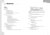
... not boot up to 1.5Gb/s. - Serial ATA 4 2 on -board connectors support 4 IDE disk drives. 4 Supports PIO mode 5, Block Mode and Ultra DMA 33/66/100/133 bus master mode. ITE's "Smart Guardian" function Slots 4 One 32bit PCI bus master slot. 4 One PCI-Express x16 slot. - On-board AC'97 Audio Sound Codec 4 Chip: ALC850. 4 Compliant with AC'97 version2.3 specification. - Supports 4 SATA ports, each channel up . Certified DDR400 List: - Fan Speed Controller - Dimensions 4 Form Factor: 20.0cm (W) x 28.9cm (L) Operating Systems 4 Supports Windows 2000 and Windows XP...
... not boot up to 1.5Gb/s. - Serial ATA 4 2 on -board connectors support 4 IDE disk drives. 4 Supports PIO mode 5, Block Mode and Ultra DMA 33/66/100/133 bus master mode. ITE's "Smart Guardian" function Slots 4 One 32bit PCI bus master slot. 4 One PCI-Express x16 slot. - On-board AC'97 Audio Sound Codec 4 Chip: ALC850. 4 Compliant with AC'97 version2.3 specification. - Supports 4 SATA ports, each channel up . Certified DDR400 List: - Fan Speed Controller - Dimensions 4 Form Factor: 20.0cm (W) x 28.9cm (L) Operating Systems 4 Supports Windows 2000 and Windows XP...
MANUAL
Page 7
... out connector 4 1 PS/2 Mouse Port. 4 1 PS/2 Keyboard Port. 4 2 Serial ports. 4 4 USB 2.0 ports. 4 6 audio-out ports support 8 channels audio-out function. Isochronous controller paired with transfer up to 400Mb/s. RAID 0 disk striping for fault tolerance - Gigabit LAN 4 NVIDIA Gigabit MAC + VITESSE Gigabit PHY VSC8201. 4 Supports 10 Mb/s, 100 Mb/s and 1Gb/s auto-negotiation. 4 Half/Full duplex capability. 4 Supports personal Firewall setup. 4 Supports ACPI power management. 4 Supports NVIDIA StreamThru technology - BIOS & Software BIOS 4 Award legal BIOS. 4 Supports APM1...
... out connector 4 1 PS/2 Mouse Port. 4 1 PS/2 Keyboard Port. 4 2 Serial ports. 4 4 USB 2.0 ports. 4 6 audio-out ports support 8 channels audio-out function. Isochronous controller paired with transfer up to 400Mb/s. RAID 0 disk striping for fault tolerance - Gigabit LAN 4 NVIDIA Gigabit MAC + VITESSE Gigabit PHY VSC8201. 4 Supports 10 Mb/s, 100 Mb/s and 1Gb/s auto-negotiation. 4 Half/Full duplex capability. 4 Supports personal Firewall setup. 4 Supports ACPI power management. 4 Supports NVIDIA StreamThru technology - BIOS & Software BIOS 4 Award legal BIOS. 4 Supports APM1...
MANUAL
Page 8
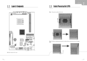
Step 2: Pull the lever sideways away from the socket and then raise the lever up to a 90-degree angle. 2.2 Layout & Components 2.3 Central Processing Unit (CPU) Step 1 : Remove the socket protection cap. Note: represents the 1st pin.
Step 2: Pull the lever sideways away from the socket and then raise the lever up to a 90-degree angle. 2.2 Layout & Components 2.3 Central Processing Unit (CPU) Step 1 : Remove the socket protection cap. Note: represents the 1st pin.
MANUAL
Page 9
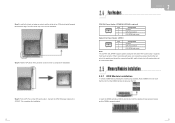
... that the notch on the DIMM matches the break on the Slot. 2. Step 5: Put the CPU Fan on CPU should be connected to GND. 2.5 Memory Modules Installation 2.5.1 DDR Module installation 1. Unlock a DIMM slot by pressing the retaining clips outward. Connect the CPU FAN power cable to complete the installation. It supports 3 pin head connector. This completes the installation. 2.4 Fan Headers CPU FAN Power Header: JCFAN1&2 (JCFAN2 is properly seated. Insert the DIMM vertically and firmly...
... that the notch on the DIMM matches the break on the Slot. 2. Step 5: Put the CPU Fan on CPU should be connected to GND. 2.5 Memory Modules Installation 2.5.1 DDR Module installation 1. Unlock a DIMM slot by pressing the retaining clips outward. Connect the CPU FAN power cable to complete the installation. It supports 3 pin head connector. This completes the installation. 2.4 Fan Headers CPU FAN Power Header: JCFAN1&2 (JCFAN2 is properly seated. Insert the DIMM vertically and firmly...
MANUAL
Page 10
... two HDD connectors IDE1 (primary) and IDE2 (secondary). This PCI slot is a bus standard for expansion cards. The first hard drive should always be connected to four hard disk drives. Serial ATA Connectors: JSATA1~JSATA2 The motherboard has a SATA Controller in nForce4 (CK8-04) with 4 channels SATA interface, it will provide +12V to PCI-Express x16 slot. When the jumper cap is placed on the ATX power supply. JATXPWR1 1 6 7 12 JATXPWR2 JATXPWR3 Pin Assignment 1 +12V 2 +12V Pin Assignment...
... two HDD connectors IDE1 (primary) and IDE2 (secondary). This PCI slot is a bus standard for expansion cards. The first hard drive should always be connected to four hard disk drives. Serial ATA Connectors: JSATA1~JSATA2 The motherboard has a SATA Controller in nForce4 (CK8-04) with 4 channels SATA interface, it will provide +12V to PCI-Express x16 slot. When the jumper cap is placed on the ATX power supply. JATXPWR1 1 6 7 12 JATXPWR2 JATXPWR3 Pin Assignment 1 +12V 2 +12V Pin Assignment...
MANUAL
Page 11
... USB Ports: 1394_USBV5/LAN_USBV3 31 Pin 1-2 close 31 Pin 2-3 close Voltage 3 PS/2 keyboard and mouse are powered with +5V standby voltage. JCDIN1 4 1 Pin Assignment 1 Left channel input 2 Ground 3 Ground 4 Right channel input Power Source Header for 1394 Chip: J1394PWR1 Assignment 1 +3.3V Pin 1-2 close 3 Description +3.3V for 1394 chipset. (Default) 1 Pin 2-3 close +3.3V SB 3 +3.3V SB for 1394 chipset. Note: In order to connect the audio source from the variety devices, like CD-ROM, DVD-ROM, PCI sound card, PCI...
... USB Ports: 1394_USBV5/LAN_USBV3 31 Pin 1-2 close 31 Pin 2-3 close Voltage 3 PS/2 keyboard and mouse are powered with +5V standby voltage. JCDIN1 4 1 Pin Assignment 1 Left channel input 2 Ground 3 Ground 4 Right channel input Power Source Header for 1394 Chip: J1394PWR1 Assignment 1 +3.3V Pin 1-2 close 3 Description +3.3V for 1394 chipset. (Default) 1 Pin 2-3 close +3.3V SB 3 +3.3V SB for 1394 chipset. Note: In order to connect the audio source from the variety devices, like CD-ROM, DVD-ROM, PCI sound card, PCI...

MANUAL
Page 12
... seconds. 4. Clear CMOS Procedures: 1. Power on pin2-3, it allows user to restore the BIOS safe setting and the CMOS data, please carefully follow the procedures to support this function "Power-on system via USB device," "FIO_USBV1" jumper cap should be placed on Pin 2-3 individually. Set the jumper to "Pin 1-2 close +5V standby Voltage FIO3/4 powered with standby voltage of 5V 1 Note: In order to avoid damaging the motherboard. Close CMOS Header: JCMOS1 By...
... seconds. 4. Clear CMOS Procedures: 1. Power on pin2-3, it allows user to restore the BIOS safe setting and the CMOS data, please carefully follow the procedures to support this function "Power-on system via USB device," "FIO_USBV1" jumper cap should be placed on Pin 2-3 individually. Set the jumper to "Pin 1-2 close +5V standby Voltage FIO3/4 powered with standby voltage of 5V 1 Note: In order to avoid damaging the motherboard. Close CMOS Header: JCMOS1 By...

MANUAL
Page 13
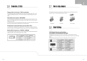
3.1 Overview 3.2 Connecting Peripheral Devices RJ-45 USB 20 21
3.1 Overview 3.2 Connecting Peripheral Devices RJ-45 USB 20 21

MANUAL
Page 14
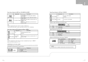
To connect a monitor, plug the monitor cable into the VGA port located on the rear panel of your computer, or on the VGA card bracket. 22 23
To connect a monitor, plug the monitor cable into the VGA port located on the rear panel of your computer, or on the VGA card bracket. 22 23
MANUAL
Page 17
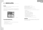
4.1 Installing Drives and Utilities 28 29
4.1 Installing Drives and Utilities 28 29

MANUAL
Page 18
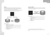
... system environment. 4.2 NVIDIA RAID Operation System: 4 Windows XP home Edition 4 Windows XP Professional Edition 4 Windows 2000 Professiona RAID Arrays: NVRAID supports the following types of RAID arrays: RAID 0: RAID 0 defines a disk striping scheme that does not require fault tolerance. 4 Benefits: provides increased data throughput, especially for large files. This technique reduces overall disk access time and offers high bandwidth. Features and Benefits 4 Drives: Minimum 1, and maximum...
... system environment. 4.2 NVIDIA RAID Operation System: 4 Windows XP home Edition 4 Windows XP Professional Edition 4 Windows 2000 Professiona RAID Arrays: NVRAID supports the following types of RAID arrays: RAID 0: RAID 0 defines a disk striping scheme that does not require fault tolerance. 4 Benefits: provides increased data throughput, especially for large files. This technique reduces overall disk access time and offers high bandwidth. Features and Benefits 4 Drives: Minimum 1, and maximum...
MANUAL
Page 19
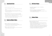
... data can be applied for the storage space of a hardware failure. Each drive is accessed as a form of Disks". This is useful when a single drive configuration is corrupted or becomes unavailable because of one drive fail, the controller switches to download NVIDIA nForce Tutorial Flash. 33 RAID 1 provides a hot-standby copy of data if the active volume or drive is needed, but it were on...
... data can be applied for the storage space of a hardware failure. Each drive is accessed as a form of Disks". This is useful when a single drive configuration is corrupted or becomes unavailable because of one drive fail, the controller switches to download NVIDIA nForce Tutorial Flash. 33 RAID 1 provides a hot-standby copy of data if the active volume or drive is needed, but it were on...
MANUAL
Page 21
5 . 1 System Does Not Start 5 . 3 USB Device Problems 5 . 2 Keyboard and Mouse Problems 5 . 4 Software Problem 36 37
5 . 1 System Does Not Start 5 . 3 USB Device Problems 5 . 2 Keyboard and Mouse Problems 5 . 4 Software Problem 36 37

MANUAL
Page 23
6 . 1 General Maintenance 6 . 2 Safe Use of the System 40 41
6 . 1 General Maintenance 6 . 2 Safe Use of the System 40 41


