Owners Manual
Page 1
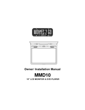
Owner/ Installation Manual MMD10 10" LCD MONITOR & DVD PLAYER
Owner/ Installation Manual MMD10 10" LCD MONITOR & DVD PLAYER
Owners Manual
Page 2
... video monitor. Lock the LCD screen in the fully closed position when not in the off or auto positions when the vehicle is unattended, as the dome lights, if left on, can drain the vehicle s battery. Reverse engineering or disassembly is dirty. Use...viewing uses only unless authorized by Macrovision Corporation, and is intended for home and other rights owners. Do not put pressure on headphones always adjust the volume setting to leave the dome light switch in use any abrasive cleaners, they may scratch the screen. Use only a lightly dampened lint free cloth to wipe the screen...
... video monitor. Lock the LCD screen in the fully closed position when not in the off or auto positions when the vehicle is unattended, as the dome lights, if left on, can drain the vehicle s battery. Reverse engineering or disassembly is dirty. Use...viewing uses only unless authorized by Macrovision Corporation, and is intended for home and other rights owners. Do not put pressure on headphones always adjust the volume setting to leave the dome light switch in use any abrasive cleaners, they may scratch the screen. Use only a lightly dampened lint free cloth to wipe the screen...
Owners Manual
Page 3
... driver's seat where it will not be installed so that operates when the vehicle is in "park" or when the vehicle's parking brake is used for television reception, video or DVD play , the LCD panel or video monitor must be installed to the rear of the motor vehicle. 3 If the LCD panel or video monitor is applied. An LCD panel or video monitor used for vehicle information, system control, rear or side observation or navigation...
... driver's seat where it will not be installed so that operates when the vehicle is in "park" or when the vehicle's parking brake is used for television reception, video or DVD play , the LCD panel or video monitor must be installed to the rear of the motor vehicle. 3 If the LCD panel or video monitor is applied. An LCD panel or video monitor used for vehicle information, system control, rear or side observation or navigation...
Owners Manual
Page 4
... of reliable, trouble-free service. Please read the entire instruction manual supplied with the instructions and illustrations provided in installing the system properly to Laser Radiation. A. Installation Ensure that the MMD10 is constructed to provide years of the system only. 4 There is unplugged from the power source. The main features include a 10" Wide Screen (16:9 Aspect Ratio) Liquid Crystal Display (LCD) monitor and a built-in DVD player. B.
... of reliable, trouble-free service. Please read the entire instruction manual supplied with the instructions and illustrations provided in installing the system properly to Laser Radiation. A. Installation Ensure that the MMD10 is constructed to provide years of the system only. 4 There is unplugged from the power source. The main features include a 10" Wide Screen (16:9 Aspect Ratio) Liquid Crystal Display (LCD) monitor and a built-in DVD player. B.
Owners Manual
Page 5
... unit plays discs according to the instructions supplied with a cleaning cloth. CONTENTS 1. 10" LCD Monitor & DVD Player Combo 2. Remote Control 6. Do not touch the surface of discs may not be intentionally fixed by software producers. A/V Adapter Cable 3. 5. Remove the disc from the center out with the discs. Some playback operations of disc. Hardware Package 4 pcs M4 x 16mm Machine Screws 4 pcs M4 x 25mm Screws 4 pcs 2.6x10mm Screws 4 pcs Small Rubber Rings 4 pcs Connecting...
... unit plays discs according to the instructions supplied with a cleaning cloth. CONTENTS 1. 10" LCD Monitor & DVD Player Combo 2. Remote Control 6. Do not touch the surface of discs may not be intentionally fixed by software producers. A/V Adapter Cable 3. 5. Remove the disc from the center out with the discs. Some playback operations of disc. Hardware Package 4 pcs M4 x 16mm Machine Screws 4 pcs M4 x 25mm Screws 4 pcs 2.6x10mm Screws 4 pcs Small Rubber Rings 4 pcs Connecting...
Owners Manual
Page 6
Installation and Powering TOOLS REQUIRED: #2 Philips Screwdriver #1 Philips Screwdriver Utility or Razor Knife or Shears Wire Strippers Upholstery hook tool (for removal of panels as necessary) Electrical Tape Masking Tape Multimeter (to verify 12 volt DC and continuity: Do not use a test light or logic probe) Marker pen # to mark headliner Scribe (to vehicle. 6 Requirements will vary from vehicle to mark trim ring if used) Misc. D. electrical connectors (to connect to vehicle power source).
Installation and Powering TOOLS REQUIRED: #2 Philips Screwdriver #1 Philips Screwdriver Utility or Razor Knife or Shears Wire Strippers Upholstery hook tool (for removal of panels as necessary) Electrical Tape Masking Tape Multimeter (to verify 12 volt DC and continuity: Do not use a test light or logic probe) Marker pen # to mark headliner Scribe (to vehicle. 6 Requirements will vary from vehicle to mark trim ring if used) Misc. D. electrical connectors (to connect to vehicle power source).
Owners Manual
Page 7
.... 5) Route the wiring harnesses throughout the vehicle as necessary. (Refer to the Wiring Diagrams on page 10 of all components are fully installed. GENERAL INSTALLATION APPROACH: 1) Decide upon system configuration and options that will be installed (i.e.: what components, VCP, Tuner, RF Modulator/external amp, remote headphones, DVD, etc.). 2) Review all manuals to become familiar with electrical requirements and hook ups. 3) Decide upon mounting locations of all...
.... 5) Route the wiring harnesses throughout the vehicle as necessary. (Refer to the Wiring Diagrams on page 10 of all components are fully installed. GENERAL INSTALLATION APPROACH: 1) Decide upon system configuration and options that will be installed (i.e.: what components, VCP, Tuner, RF Modulator/external amp, remote headphones, DVD, etc.). 2) Review all manuals to become familiar with electrical requirements and hook ups. 3) Decide upon mounting locations of all...
Owners Manual
Page 8
... INSTALL THE MONITOR IN A PLACE WITHIN THE DRIVER'S VIEW. B) The headliner may need to vehicle, so this wire can be required are: A) Removal of the vehicle's dome light. Generally, this manual will only focus on the vehicle structure and installation method. The monitor should be located in the ACC. THIS IS NOT ONLY DANGEROUS, BUT IT IS ALSO ILLEGAL. 4) Once the mounting location...
... INSTALL THE MONITOR IN A PLACE WITHIN THE DRIVER'S VIEW. B) The headliner may need to vehicle, so this wire can be required are: A) Removal of the vehicle's dome light. Generally, this manual will only focus on the vehicle structure and installation method. The monitor should be located in the ACC. THIS IS NOT ONLY DANGEROUS, BUT IT IS ALSO ILLEGAL. 4) Once the mounting location...
Owners Manual
Page 12
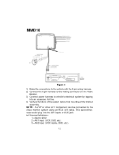
... the 5 pin wiring harness. 2) Connect the 5 pin harness to the mating connector on the Video Monitor. 3) Connect power harness to the video monitor system using an RCA A/V cable. This second harness would plug into an accessory hot line. 4) Verify all functions of the system before final mounting of the finished assembly. NOTE: A VCP or other A/V Component can be connected to vehicle's electrical system by tapping into the AV1 inputs or AUX jack. A/V Source Definitions...
... the 5 pin wiring harness. 2) Connect the 5 pin harness to the mating connector on the Video Monitor. 3) Connect power harness to the video monitor system using an RCA A/V cable. This second harness would plug into an accessory hot line. 4) Verify all functions of the system before final mounting of the finished assembly. NOTE: A VCP or other A/V Component can be connected to vehicle's electrical system by tapping into the AV1 inputs or AUX jack. A/V Source Definitions...
Owners Manual
Page 13
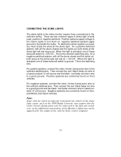
... (Lamp auto) wire to the vehicle's switched wire. Positive systems supply voltage to the interior lights to turn them on ) wire to a good ground and the black / red (lamp common) wire to ground. When the light is the vehicle's switching wire. This is activated, one of dome light circuits used, positive or negative switched. Negative systems are commonly found on ) wire to a fused constant 12 volt source and the black / red (lamp common) wire to...
... (Lamp auto) wire to the vehicle's switched wire. Positive systems supply voltage to the interior lights to turn them on ) wire to a good ground and the black / red (lamp common) wire to ground. When the light is the vehicle's switching wire. This is activated, one of dome light circuits used, positive or negative switched. Negative systems are commonly found on ) wire to a fused constant 12 volt source and the black / red (lamp common) wire to...
Owners Manual
Page 14
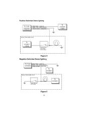
Lamp on Monitor Red / black - Lamp common Violet / brown - Positive Switched Dome lighting To 3 pin connector on Black / red - Lamp Auto To constant +12vdc Factory Dome light circuit To constant +12vdc Factory Door ajar switch or Body Control computer Figure 4 Negative Switched Dome lighting To 3 pin connector Red / black - Lamp Auto To constant Factory Dome light circuit Factory Door ajar switch or Body To constant Figure 5 14 Lamp common Violet / brown - Lamp on Black / red -
Lamp on Monitor Red / black - Lamp common Violet / brown - Positive Switched Dome lighting To 3 pin connector on Black / red - Lamp Auto To constant +12vdc Factory Dome light circuit To constant +12vdc Factory Door ajar switch or Body Control computer Figure 4 Negative Switched Dome lighting To 3 pin connector Red / black - Lamp Auto To constant Factory Dome light circuit Factory Door ajar switch or Body To constant Figure 5 14 Lamp common Violet / brown - Lamp on Black / red -
Owners Manual
Page 15
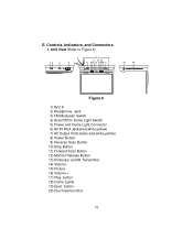
Unit View (Refer to Figure 6) Figure 6 1) AV 2 In 2) Headphone Jack 3) FM Modulator Switch 4) Auto/Off/On Dome Light Switch 5) Power and Dome Light Connector 6) AV IN RCA Jacks(red,white,yellow) 7) AV Output RCA Jacks (red,white,yellow) 8) Power Button 9) Reverse Scan Button 10) Stop Button 11) Forward Scan Button 12) Monitor Release Button 13) IR Sensor and IR Transmitter 14) Volume 15) Picture 16) Volume + 17) Play button 18) Dome Lights 19) Eject button 20) Disc Insertion Slot 15 Controls, Indicators, and Connectors 1. E.
Unit View (Refer to Figure 6) Figure 6 1) AV 2 In 2) Headphone Jack 3) FM Modulator Switch 4) Auto/Off/On Dome Light Switch 5) Power and Dome Light Connector 6) AV IN RCA Jacks(red,white,yellow) 7) AV Output RCA Jacks (red,white,yellow) 8) Power Button 9) Reverse Scan Button 10) Stop Button 11) Forward Scan Button 12) Monitor Release Button 13) IR Sensor and IR Transmitter 14) Volume 15) Picture 16) Volume + 17) Play button 18) Dome Lights 19) Eject button 20) Disc Insertion Slot 15 Controls, Indicators, and Connectors 1. E.
Owners Manual
Page 16
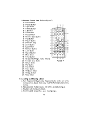
Remote Control View (Refer to Figure 7) 1) Power Button 2) Display Button 3) Angle Button 4) Subtitle Button 5) A-B Button 6) Slow Button 7) Pause Button 8) Reverse Scan Button 9) Stop Button 10) Picture Button 11) DVD /AV1 /AV2 12) Zoom Button 13) Eject Button 14) Numeric Buttons 15) Audio Button 16) Repeat Button 17) Menu Button 18) Setup Button 19) Up/Down/Left/Right / Enter Buttons 20) Forward Scan Button 21) Return Button 22) Play Button 23) Skip- Button 24) Skip+ Button 25) Vol Down Button 26) Vol Up+ Button 27) Wide Button Figure 7 F. Pivot the LCD Screen for...
Remote Control View (Refer to Figure 7) 1) Power Button 2) Display Button 3) Angle Button 4) Subtitle Button 5) A-B Button 6) Slow Button 7) Pause Button 8) Reverse Scan Button 9) Stop Button 10) Picture Button 11) DVD /AV1 /AV2 12) Zoom Button 13) Eject Button 14) Numeric Buttons 15) Audio Button 16) Repeat Button 17) Menu Button 18) Setup Button 19) Up/Down/Left/Right / Enter Buttons 20) Forward Scan Button 21) Return Button 22) Play Button 23) Skip- Button 24) Skip+ Button 25) Vol Down Button 26) Vol Up+ Button 27) Wide Button Figure 7 F. Pivot the LCD Screen for...
Owners Manual
Page 17
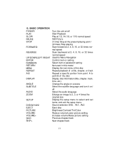
... point B of the disc Display disc information (title, chapter, track, time, etc.) Change the angle on a scene Select the subtitle language and turn it on/ off Select the audio language Enlarge an image to 2 ,3, or 4 times the original size Display the setup menu to select and set items, and exit the setup menu. Source selection DVD, AV1, AV2 Eject disc Brightness/Contrast/Tint/Color Reduce volume/Lower picture setting Increase volume/Raise picture setting Previous chapter/track...
... point B of the disc Display disc information (title, chapter, track, time, etc.) Change the angle on a scene Select the subtitle language and turn it on/ off Select the audio language Enlarge an image to 2 ,3, or 4 times the original size Display the setup menu to select and set items, and exit the setup menu. Source selection DVD, AV1, AV2 Eject disc Brightness/Contrast/Tint/Color Reduce volume/Lower picture setting Increase volume/Raise picture setting Previous chapter/track...
Owners Manual
Page 20
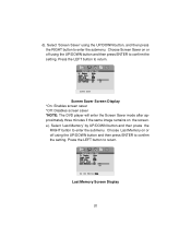
... setting. Screen Saver Screen Display *On: Enables screen saver *Off: Disables screen saver *NOTE: The DVD player will enter the Screen Saver mode after approximately three minutes if the same image remains on or off using the UP/DOWN button and then press ENTER to return. Choose Screen Saver on or off using the UP/DOWN button and then press ENTER to enter the submenu. Last Memory Screen Display...
... setting. Screen Saver Screen Display *On: Enables screen saver *Off: Disables screen saver *NOTE: The DVD player will enter the Screen Saver mode after approximately three minutes if the same image remains on or off using the UP/DOWN button and then press ENTER to return. Choose Screen Saver on or off using the UP/DOWN button and then press ENTER to enter the submenu. Last Memory Screen Display...
Owners Manual
Page 23
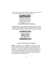
... of users while some discs cannot. 23 Input the Old Password or the Default Password, the New Password, and the Confirmed New Password. 3).Select "Password" using the default password to enter the Password Change Page. Some discs can record this manual. Password Change Page Screen Display NOTE: The Default Password is always effective even after you can be limited depending on the age of others using the LEFT/RIGHT button, then...
... of users while some discs cannot. 23 Input the Old Password or the Default Password, the New Password, and the Confirmed New Password. 3).Select "Password" using the default password to enter the Password Change Page. Some discs can record this manual. Password Change Page Screen Display NOTE: The Default Password is always effective even after you can be limited depending on the age of others using the LEFT/RIGHT button, then...
Owners Manual
Page 31
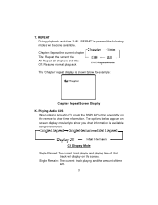
... display is shown below appear on the screen. REPEAT During playback each time '1/ALL REPEAT' is available using this function. Single Remain: The current track playing and the amount of that track will become available. Playing Audio CDS When playing an audio CD press the DISPLAY button repeatedly on the remote to show you what information is pressed, the following modes will display on screen display circularly to view time...
... display is shown below appear on the screen. REPEAT During playback each time '1/ALL REPEAT' is available using this function. Single Remain: The current track playing and the amount of that track will become available. Playing Audio CDS When playing an audio CD press the DISPLAY button repeatedly on the remote to show you what information is pressed, the following modes will display on screen display circularly to view time...
Owners Manual
Page 35
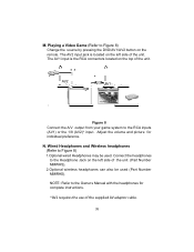
The AV2 input jack is the RCA connectors located on the remote. N. Adjust the volume and picture for complete instructions. *AV2 requires the use of the unit (Part Number MMWHS). 2.Optional wireless headphones can also be used (Part Number MMIRHS). NOTE: Refer to the RCA inputs (AV1) or the 1/8 (AV2)* input. AV2 AV1 Figure 8 Connect the A/V output from your game system to the Owner s Manual with the headphones for individual preference. Connect the headphones to...
The AV2 input jack is the RCA connectors located on the remote. N. Adjust the volume and picture for complete instructions. *AV2 requires the use of the unit (Part Number MMWHS). 2.Optional wireless headphones can also be used (Part Number MMIRHS). NOTE: Refer to the RCA inputs (AV1) or the 1/8 (AV2)* input. AV2 AV1 Figure 8 Connect the A/V output from your game system to the Owner s Manual with the headphones for individual preference. Connect the headphones to...
Owners Manual
Page 37
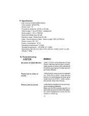
... source is selected (i.e.: DVD, AV1 or AV2). Verify ground connection with continuity test from known good ground to the same FM station. Make sure the FM modulator and the vehicle radio are turned on the Red wire at both ends of the harness. P. Specification Disc format: DVD/CD/MP3/JPEG Color system: NTSC/PAL Screen size: 10" Frequency response: 20 Hz to 20 kHz Video output: 1 Vp-p/75 Ohm, unbalanced Audio output...
... source is selected (i.e.: DVD, AV1 or AV2). Verify ground connection with continuity test from known good ground to the same FM station. Make sure the FM modulator and the vehicle radio are turned on the Red wire at both ends of the harness. P. Specification Disc format: DVD/CD/MP3/JPEG Color system: NTSC/PAL Screen size: 10" Frequency response: 20 Hz to 20 kHz Video output: 1 Vp-p/75 Ohm, unbalanced Audio output...

Owners Manual
Page 38
... extend to the elimination of externally generated static or noise, to correction of antenna problems, to costs incurred for installation, removal or reinstallation of the factory serial number/bar code label(s). 12 MONTH LIMITED WARRANTY Applies to Movies To Go Mobile Video Products AUDIOVOX ELECTRONICS CORP. (the Company) warrants to state. This Warranty gives you specific legal rights and you . Some...
... extend to the elimination of externally generated static or noise, to correction of antenna problems, to costs incurred for installation, removal or reinstallation of the factory serial number/bar code label(s). 12 MONTH LIMITED WARRANTY Applies to Movies To Go Mobile Video Products AUDIOVOX ELECTRONICS CORP. (the Company) warrants to state. This Warranty gives you specific legal rights and you . Some...


