
Owners Manual
Page 2
... harmful interference to radio or television reception, which can be used in a particular installation. The symbol for help. Let the unit stand for 1-2 hours before turning the power on bedding or carpeting. This equipment generates, used with this unit by placing it somewhere with...the cord itself. Pulling the cord may not function normally. When there is connected. • Consult the dealer or an experienced radio/TV technician for Class II (Double lnsulation) PLACEMENT INFORMATION • Do not use . FCC INFORMATION WARNING: Changes or modifications to this unit...
... harmful interference to radio or television reception, which can be used in a particular installation. The symbol for help. Let the unit stand for 1-2 hours before turning the power on bedding or carpeting. This equipment generates, used with this unit by placing it somewhere with...the cord itself. Pulling the cord may not function normally. When there is connected. • Consult the dealer or an experienced radio/TV technician for Class II (Double lnsulation) PLACEMENT INFORMATION • Do not use . FCC INFORMATION WARNING: Changes or modifications to this unit...

Owners Manual
Page 3
..., heat registers, stoves, or other . Only use caution when moving the cart/apparatus combination to avoid injury from the apparatus. Use only with the cart, stand, tripod, bracket, or table specified by the manufacture. Follow all warnings. Unplug this apparatus near any ventilation openings. Read these instructions. Clean only with the...
..., heat registers, stoves, or other . Only use caution when moving the cart/apparatus combination to avoid injury from the apparatus. Use only with the cart, stand, tripod, bracket, or table specified by the manufacture. Follow all warnings. Unplug this apparatus near any ventilation openings. Read these instructions. Clean only with the...

Owners Manual
Page 4
... a High-Definition (HD) Source ...12 Connecting a PC ...12 Connecting an Audio Amplifier ...13 Using the Power Cord ...13 INSTALLATION ...14 Removing the Base Stand ...14 Mounting on the Wall ...14 USING HEADPHONES ...15 UNIT OPERATION ...15 Turning the Unit on for the First Time ...15... ...16 - 21 Video Menu ...16 VGA Settings in PC Mode ...17 Audio Menu ...17 TV Menu ...18 Channel Skip Setting ...18 Setup Menu ...18 - 20 Time Setup Setting ...19 Caption Setting ...20 Restore Setting ...20 Parental Menu ...20 - 21 Password ...20 Parental Control Setting ...21 TROUBLE SHOOTING GUIDE ...22 4...
... a High-Definition (HD) Source ...12 Connecting a PC ...12 Connecting an Audio Amplifier ...13 Using the Power Cord ...13 INSTALLATION ...14 Removing the Base Stand ...14 Mounting on the Wall ...14 USING HEADPHONES ...15 UNIT OPERATION ...15 Turning the Unit on for the First Time ...15... ...16 - 21 Video Menu ...16 VGA Settings in PC Mode ...17 Audio Menu ...17 TV Menu ...18 Channel Skip Setting ...18 Setup Menu ...18 - 20 Time Setup Setting ...19 Caption Setting ...20 Restore Setting ...20 Parental Menu ...20 - 21 Password ...20 Parental Control Setting ...21 TROUBLE SHOOTING GUIDE ...22 4...

Owners Manual
Page 7
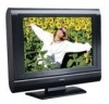
.... Light On: The unit is turned ON. UNIT REFERENCE GUIDE 1) Color LCD Screen 2) STANDBY Indicator Indicates whether the unit is ON or in STANDBY. REMOTE CONTROL SENSOR Do not block this sensor or remote control will not work. 3) Removable Base Stand 4) STANDBY/ON Button Turns the unit on the menu screen. 9) Power... Audio Jack 16) YUV IN Component Video Input Jacks (Y/PB/PR) 17) YUV IN Audio Input Jacks (Left/Right) 18) AV IN S-Video Input Jack 19) Headphone Jack 20) TV Antenna Cable Terminal - Coaxial TV Antenna Input 1 2 3 4 5 6 7 8 9 10 11 12 13 14 15 16 17 18...
.... Light On: The unit is turned ON. UNIT REFERENCE GUIDE 1) Color LCD Screen 2) STANDBY Indicator Indicates whether the unit is ON or in STANDBY. REMOTE CONTROL SENSOR Do not block this sensor or remote control will not work. 3) Removable Base Stand 4) STANDBY/ON Button Turns the unit on the menu screen. 9) Power... Audio Jack 16) YUV IN Component Video Input Jacks (Y/PB/PR) 17) YUV IN Audio Input Jacks (Left/Right) 18) AV IN S-Video Input Jack 19) Headphone Jack 20) TV Antenna Cable Terminal - Coaxial TV Antenna Input 1 2 3 4 5 6 7 8 9 10 11 12 13 14 15 16 17 18...

Owners Manual
Page 14
...because the screen could scratch or damage the LCD display, come in contact with it. Remove the four screws and then remove the BASE STAND from the unit. Lay the unit down ... foam) beneath the screen. 3. INSTALLATION REMOVING THE BASE STAND WARNING: The LCD Display is very fragile, and must remove the base stand before mounting the unit on the wall. 14 PLV36190CS1_IB_ENG_AUD.pmd...cushioned material (such as a pillow or thick piece of the unit at all times when removing the base stand. MOUNTING ON THE WALL This unit is VESA-compliant, and is facing up, making sure to the directions ...
...because the screen could scratch or damage the LCD display, come in contact with it. Remove the four screws and then remove the BASE STAND from the unit. Lay the unit down ... foam) beneath the screen. 3. INSTALLATION REMOVING THE BASE STAND WARNING: The LCD Display is very fragile, and must remove the base stand before mounting the unit on the wall. 14 PLV36190CS1_IB_ENG_AUD.pmd...cushioned material (such as a pillow or thick piece of the unit at all times when removing the base stand. MOUNTING ON THE WALL This unit is VESA-compliant, and is facing up, making sure to the directions ...

