Motherboard DIY Troubleshooting Guide
Page 39
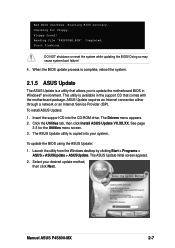
... utility is available in the support CD that allows you to update the motherboard BIOS in Windows® environment. See page 3-3 for floppy... To update the BIOS using the ASUS Update: 1. Select your system. Checking for the Utilities menu screen. 3....ASUS Update: 1. The ASUS Update initial screen appears. 2. ASUS Update requires an Internet connection either through a network or an Internet Service Provider (ISP). Bad BIOS checksum. Completed. Launch the utility from the Windows desktop by clicking Start > Programs > ASUS > ASUSUpdate > ASUSUpdate. Reading file "P4S800MX...
... utility is available in the support CD that allows you to update the motherboard BIOS in Windows® environment. See page 3-3 for floppy... To update the BIOS using the ASUS Update: 1. Select your system. Checking for the Utilities menu screen. 3....ASUS Update: 1. The ASUS Update initial screen appears. 2. ASUS Update requires an Internet connection either through a network or an Internet Service Provider (ISP). Bad BIOS checksum. Completed. Launch the utility from the Windows desktop by clicking Start > Programs > ASUS > ASUSUpdate > ASUSUpdate. Reading file "P4S800MX...
P4S800-MX English User Manual E1447
Page 6
...damage, contact your dealer immediately. • To avoid short circuits, keep paper clips, screws, and staples away from the motherboard, ensure that the power cables for the devices are unplugged before you encounter technical problems with the package. • Before ...professional assistance before using an adpater or extension cord. Operation safety • Before installing the motherboard and adding devices on a stable surface. • If you add a device. • Before connecting or removing signal cables from connectors, slots, sockets and circuitry. • Avoid dust,...
...damage, contact your dealer immediately. • To avoid short circuits, keep paper clips, screws, and staples away from the motherboard, ensure that the power cables for the devices are unplugged before you encounter technical problems with the package. • Before ...professional assistance before using an adpater or extension cord. Operation safety • Before installing the motherboard and adding devices on a stable surface. • If you add a device. • Before connecting or removing signal cables from connectors, slots, sockets and circuitry. • Avoid dust,...
P4S800-MX English User Manual E1447
Page 12
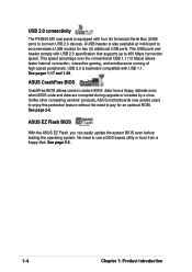
... BIOS CrashFree BIOS allows users to pay for two (2) additional USB ports. Unlike other competing vendors' products, ASUS motherboards now enable users to enjoy this protection feature without the need to connect USB 2.0 devices. No need to restore BIOS data from a floppy disk. See page 2-3. 1-4 Chapter 1: Product introduction USB 2.0 is equipped with four...
... BIOS CrashFree BIOS allows users to pay for two (2) additional USB ports. Unlike other competing vendors' products, ASUS motherboards now enable users to enjoy this protection feature without the need to connect USB 2.0 devices. No need to restore BIOS data from a floppy disk. See page 2-3. 1-4 Chapter 1: Product introduction USB 2.0 is equipped with four...

P4S800-MX English User Manual E1447
Page 17
.... 7. When the CPU is in one correct orientation. Gold Mark ASUS P4S800-MX motherboard user guide 1-9 Locate the 478-pin ZIF socket on the motherboard. The CPU fits only in place, push down the socket lever to secure the CPU. Connect the CPU fan cable to 90°-100° angle, otherwise ...the CPU does not fit in place. Unlock the socket by pressing the lever sideways, then lift it up to the CPU_FAN1 connector on the motherboard. 2. Install a CPU heatsink and fan ...
.... 7. When the CPU is in one correct orientation. Gold Mark ASUS P4S800-MX motherboard user guide 1-9 Locate the 478-pin ZIF socket on the motherboard. The CPU fits only in place, push down the socket lever to secure the CPU. Connect the CPU fan cable to 90°-100° angle, otherwise ...the CPU does not fit in place. Unlock the socket by pressing the lever sideways, then lift it up to the CPU_FAN1 connector on the motherboard. 2. Install a CPU heatsink and fan ...

P4S800-MX English User Manual E1447
Page 25
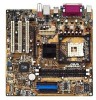
...Connectors This section describes and illustrates the motherboard rear panel and internal connectors. 1.10.1 Rear panel connectors 1 2 3 4 5 6 11 10 9 8 7 1. PS/2 mouse port. This green 6-pin connector is for a PS/2 keyboard. This 25-pin port connects a parallel printer, scanner, or ...; 98SE only supports 2-channel speaker configuration. 7. Serial port. ASUS P4S800-MX motherboard user guide 1-17 In 6-channel mode, the function of this jack becomes Bass/Center. 5. USB 2.0 ports 1 and 2. This port connects a VGA compatible monitor. 10. Line In jack. Microphone jack...
...Connectors This section describes and illustrates the motherboard rear panel and internal connectors. 1.10.1 Rear panel connectors 1 2 3 4 5 6 11 10 9 8 7 1. PS/2 mouse port. This green 6-pin connector is for a PS/2 keyboard. This 25-pin port connects a parallel printer, scanner, or ...; 98SE only supports 2-channel speaker configuration. 7. Serial port. ASUS P4S800-MX motherboard user guide 1-17 In 6-channel mode, the function of this jack becomes Bass/Center. 5. USB 2.0 ports 1 and 2. This port connects a VGA compatible monitor. 10. Line In jack. Microphone jack...

P4S800-MX English User Manual E1447
Page 26
... cables. 3. Floppy disk drive connector (34-1 pin FLOPPY1) This connector supports the provided floppy drive ribbon cable. After connecting one end to the motherboard, connect the other end to the floppy drive. (Pin 5 is removed to PIN 1. P4S800-MX FLOPPY1 NOTE: Orient the red markings on the... floppy ribbon cable to prevent incorrect insertion when using ribbon cables with pin 5 plug). Connect the cable's blue connector to the primary (...
... cables. 3. Floppy disk drive connector (34-1 pin FLOPPY1) This connector supports the provided floppy drive ribbon cable. After connecting one end to the motherboard, connect the other end to the floppy drive. (Pin 5 is removed to PIN 1. P4S800-MX FLOPPY1 NOTE: Orient the red markings on the... floppy ribbon cable to prevent incorrect insertion when using ribbon cables with pin 5 plug). Connect the cable's blue connector to the primary (...

P4S800-MX English User Manual E1447
Page 27
... ATX +12V power plug to provide sufficient power to the CPU. In addition to the 20-pin ATXPWR connector, this motherboard requires that allows convenient connection and control of audio devices. P4S800-MX ATX12V1 ATXPWR1 +12V DC GND P4S800-MX ATX Power Connector +12V DC +12...BLINE_OUT_R BLINE_OUT_L FP_AUDIO1 P4S800-MX Front Panel Audio Connector ASUS P4S800-MX motherboard user guide MIC2 MICPWR Line out_R NC Line out_L 1-19 Be default, the pins labeled LINE OUT_R/BLINE_OUT_R and the pins LINE OUT_L/BLINE_OUT_L are connecting the front panel audio cable. 3. Make sure that...
... ATX +12V power plug to provide sufficient power to the CPU. In addition to the 20-pin ATXPWR connector, this motherboard requires that allows convenient connection and control of audio devices. P4S800-MX ATX12V1 ATXPWR1 +12V DC GND P4S800-MX ATX Power Connector +12V DC +12...BLINE_OUT_R BLINE_OUT_L FP_AUDIO1 P4S800-MX Front Panel Audio Connector ASUS P4S800-MX motherboard user guide MIC2 MICPWR Line out_R NC Line out_L 1-19 Be default, the pins labeled LINE OUT_R/BLINE_OUT_R and the pins LINE OUT_L/BLINE_OUT_L are connecting the front panel audio cable. 3. Make sure that...

P4S800-MX English User Manual E1447
Page 28
...5V USB_P5USB_P5+ GND P4S800-MX USB 2.0 Header USB56 1 The USB module is available for connecting next generation USB peripherals such as high resolution cameras, scanners, and printers. You may damage the motherboard components. Lack of an optional USB 2.0 module to the fan connectors. These are inadequate,... CHA_FAN1) The fan connectors support cooling fans of 350mA~740mA (8.88W max.) or a total of the connector. Connect the fan cables to the fan connectors on the motherboard, making sure that the black wire of each cable matches the ground pin of 1A~2.22A (26.64W max...
...5V USB_P5USB_P5+ GND P4S800-MX USB 2.0 Header USB56 1 The USB module is available for connecting next generation USB peripherals such as high resolution cameras, scanners, and printers. You may damage the motherboard components. Lack of an optional USB 2.0 module to the fan connectors. These are inadequate,... CHA_FAN1) The fan connectors support cooling fans of 350mA~740mA (8.88W max.) or a total of the connector. Connect the fan cables to the fan connectors on the motherboard, making sure that the black wire of each cable matches the ground pin of 1A~2.22A (26.64W max...

P4S800-MX English User Manual E1447
Page 29
... S/PDIF audio module. P4S800-MX AUX1 (White) Left Audio Channel Ground Ground Right Audio Channel CD1 (Black) P4S800-MX Internal Audio Connectors ASUS P4S800-MX motherboard user guide 1-21 Connect one end of the S/PDIF audio module cable to this connector and the other end to receive stereo audio input from sound sources...
... S/PDIF audio module. P4S800-MX AUX1 (White) Left Audio Channel Ground Ground Right Audio Channel CD1 (Black) P4S800-MX Internal Audio Connectors ASUS P4S800-MX motherboard user guide 1-21 Connect one end of the S/PDIF audio module cable to this connector and the other end to receive stereo audio input from sound sources...

P4S800-MX English User Manual E1447
Page 31
... connector accommodates several system front panel functions. P4S800-MX Front Panel Audio Connector • Power LED Lead (2-pin PWR_LED) This 2-pin connector connects to this connector, and the other end to the 3-pin power LED plug from the system chassis to the system power LED. IDE_LED+ ...IDE_LED- Power LED Lead (3-1 pin PLED1) This 3-1 pin connector is in sleep mode. Ground Reset ASUS P4S800-MX motherboard user guide 1-23 11. If your motherboard package comes with a 2-pin to 3-pin power LED converter, connect the 2-pin plug to this connector.
... connector accommodates several system front panel functions. P4S800-MX Front Panel Audio Connector • Power LED Lead (2-pin PWR_LED) This 2-pin connector connects to this connector, and the other end to the 3-pin power LED plug from the system chassis to the system power LED. IDE_LED+ ...IDE_LED- Power LED Lead (3-1 pin PLED1) This 3-1 pin connector is in sleep mode. Ground Reset ASUS P4S800-MX motherboard user guide 1-23 11. If your motherboard package comes with a 2-pin to 3-pin power LED converter, connect the 2-pin plug to this connector.

P4S800-MX English User Manual E1447
Page 39
...Windows desktop by clicking Start > Programs > ASUS > ASUSUpdate > ASUSUpdate. Reading file "P4S800MX.BIN". When the BIOS update process is complete, reboot the system. 2.1.5 ASUS Update The ASUS Update is a utility that comes with the motherboard package. The Drivers menu appears. 2. Click... the BIOS using the ASUS Update: 1. ASUS Update requires an Internet connection either through a network or an Internet Service Provider (ISP). Starting BIOS recovery... Start flashing... See page 3-3 for floppy... Bad BIOS checksum. ASUS P4S800-MX motherboard user guide 2-7 Checking for...
...Windows desktop by clicking Start > Programs > ASUS > ASUSUpdate > ASUSUpdate. Reading file "P4S800MX.BIN". When the BIOS update process is complete, reboot the system. 2.1.5 ASUS Update The ASUS Update is a utility that comes with the motherboard package. The Drivers menu appears. 2. Click... the BIOS using the ASUS Update: 1. ASUS Update requires an Internet connection either through a network or an Internet Service Provider (ISP). Starting BIOS recovery... Start flashing... See page 3-3 for floppy... Bad BIOS checksum. ASUS P4S800-MX motherboard user guide 2-7 Checking for...

P4S800-MX English User Manual E1447
Page 57
... [By Date]. Configuration options: [Disabled] [Everyday] [By Date] 2.5.2 Hardware Monitor CPU Temperature MB Temperature The onboard hardware monitor automatically detects and displays the motherboard and CPU temperatures. Thus, connection cannot be made on the +5VSB lead. Power Up On PCI Device [Disabled] When set to [Enabled], this parameter allows you to use... Up [Disabled] This allows an unattended or automatic system power up the computer when the external modem receives a call while the computer is off mode. ASUS P4S800-MX motherboard user guide 2-25
... [By Date]. Configuration options: [Disabled] [Everyday] [By Date] 2.5.2 Hardware Monitor CPU Temperature MB Temperature The onboard hardware monitor automatically detects and displays the motherboard and CPU temperatures. Thus, connection cannot be made on the +5VSB lead. Power Up On PCI Device [Disabled] When set to [Enabled], this parameter allows you to use... Up [Disabled] This allows an unattended or automatic system power up the computer when the external modem receives a call while the computer is off mode. ASUS P4S800-MX motherboard user guide 2-25

P4S800-MX English User Manual E1447
Page 58
... regulators. If any of devices alters the priority which IDE hard disk drive to search for details". You will show the product IDs of all connected IDE hard disk drives. 2-26 Chapter 2: BIOS information By using the or key, you can demote devices. Promotion or demotion of the fans is... [USB ZIP] IDE Hard Drive This field allows you can promote devices and by using the up . If any of the monitored items is not connected to select among the four possible types of range, the following error message appears: "Hardware Monitor found an error. Pressing [Enter] will then be ...
... regulators. If any of devices alters the priority which IDE hard disk drive to search for details". You will show the product IDs of all connected IDE hard disk drives. 2-26 Chapter 2: BIOS information By using the or key, you can demote devices. Promotion or demotion of the fans is... [USB ZIP] IDE Hard Drive This field allows you can promote devices and by using the up . If any of the monitored items is not connected to select among the four possible types of range, the following error message appears: "Hardware Monitor found an error. Pressing [Enter] will then be ...

P4S800-MX English User Manual E1447
Page 59
If you installed a non-PnP OS or if you want to prevent reassigning of all your connected ATAPI CD-ROM drives. Configuration options: [Enabled] [Disabled] Full Screen Logo [Enabled] This allows you to distribute interrupt routings other than the ...The Advanced Programmable Interrupt Controller (APIC) setting allows you to enable or disable the full screen logo display feature. Configuration options: [APIC] [PIC] ASUS P4S800-MX motherboard user guide 2-27 The Programmable Interrupt Controller (PIC) setting allows you to use a Plug-and-Play (PnP) operating system to configure the PCI...
If you installed a non-PnP OS or if you want to prevent reassigning of all your connected ATAPI CD-ROM drives. Configuration options: [Enabled] [Disabled] Full Screen Logo [Enabled] This allows you to distribute interrupt routings other than the ...The Advanced Programmable Interrupt Controller (APIC) setting allows you to enable or disable the full screen logo display feature. Configuration options: [APIC] [PIC] ASUS P4S800-MX motherboard user guide 2-27 The Programmable Interrupt Controller (PIC) setting allows you to use a Plug-and-Play (PnP) operating system to configure the PCI...


